Join Us On Social Media!

|

|

|
Download The App!
Login To
Remove Ads
Remove Ads
Login To
Remove Ads
Remove Ads
Model Boats Website
start of new boat build "ORCA"
10 Posts · 7 Followers · 39 Photos · 64 Likes
Began 2 years ago by
 United Kingdom
Follow This Thread
Not currently following
> Click to follow
> Click to follow
Latest Post 2 years ago by
| Oldest posts shown first (Show Newest First) | (Print Booklet) |
📝 start of new boat build "ORCA"
2 years ago by 🇬🇧 Rogal118 ( Lieutenant Commander)
Lieutenant Commander)✧ 163 Views · 5 Likes
Flag
💬 Add Comment
Well a decision was made quite a while ago as to what the next project was to be. At the time i was only half way through the "Brave Borderer" build, but you cant beat planning ahead and having something to look forward to. With 3 tugs, Aziz, Yorkshireman and Cervia plus the Brave in the harbour, I felt like a scale change, something not as fiddly so decided on the Orca at 1/16th scale. being a lot chunkier and not as fine detailed i felt a challenge ahead.
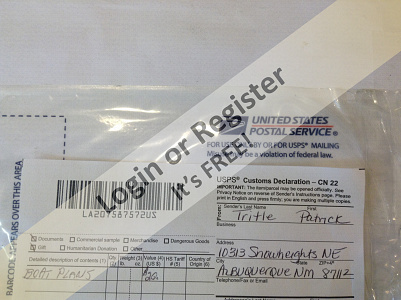
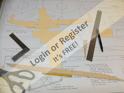
First step was to source a set of plans. these were from a guy in New Mexico, Patrick Tritle. An email to enquire the cost and an order placed, a week later they arrived. 4 large A2 sheets well drawn and highly detailed.
a list of components was made up to get me started and decisions made as to prop size, shaft length and motor, batteries etc that would be needed.
i find this part of the process as interesting as the actual build, with all the investigation into what's available and in stock. i have had excellent service from "Leeds Model shop" and "Cornwall models" and soon had the parts required to start the build
▲
⟩⟩
Julio
Seanympth
Colin H
pressonreguardless
Peejay
Login To
Remove Ads
Remove Ads
📝 orca Build
2 years ago by 🇬🇧 Rogal118 ( Lieutenant Commander)
Lieutenant Commander)✧ 162 Views · 10 Likes · 4 Comments
Flag
💬 Add Comment
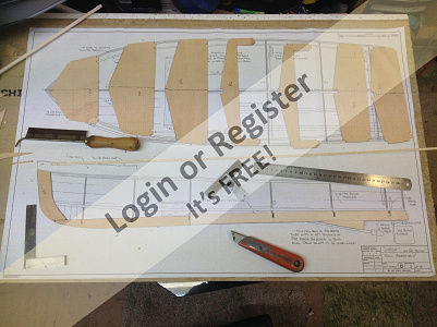
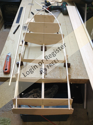
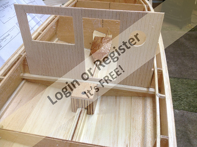
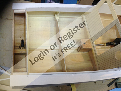
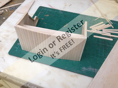
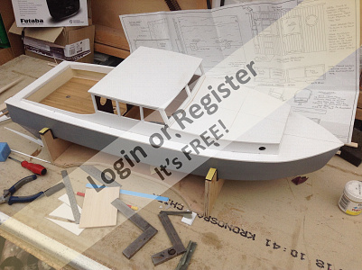
After studying the plans I set about using some stiff card to make templates of the hull bulkheads. then transferring them to some lightweight 1/8th inch ply, at the same time cutting out the keel and supports for the prop shaft. when all was cut out I had a dry run just to test the tightness of the joints and that the bulkheads where in the right position.
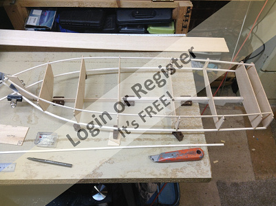
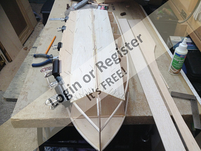
I wanted to build the hull with the keel downwards but because the prop shaft had a built in support, it was either router the bench top out or hang a third of the keel over the end of the bench. I went for the latter as can be seen in the photo.
To keep everything in line and supported I drew a centre line on the bench and worked off of that.
Then using the small plastic blocks used for joining kitchen cabinets together, I supported the keel and bulkheads to stop them twisting in the build process. using this procedure I was able to fit the deck edging beams to the bulkheads and keep them square to the keel. fitting also the inner deck beams stiffened the hull up nicely.
▲
⟩⟩
quattroo
jbkiwi
Julio
Rookysailor
Seanympth
Mike Stoney
Colin H
pressonreguardless
Peejay
Redpopman
|
💬 Re: orca Build
2 years ago by 🇪🇸 Julio (
 Petty Officer 1st Class) Petty Officer 1st Class)✧ 143 Views · 0 Likes
Flag
Hi Rogal118:
Good idea!!! ▲
⟩⟩
No likes yet
This member will receive 1 point for every like received |
|
Login To
Remove Ads 💬 Re: orca Build
2 years ago by 🇬🇧 Rogal118 (
Lieutenant Commander)✧ 150 Views · 0 Likes
Flag
Hi julio
Plans for the orca can be got from patrick as in my blog, also I have since seen them advertised from Cornwall model boats Web site. As for reference just watch the movie JAWS and freeze frame when needed and take screen shots as I did. Good surfing. ▲
⟩⟩
No likes yet
This member will receive 1 point for every like received |
|
💬 Re: orca Build
2 years ago by 🇪🇸 Julio (
Petty Officer 1st Class)✧ 146 Views · 1 Like
Flag
Hi, Rogal118:
I'll follow you in this post... and (perhaps), if I get the plans, I'll start building one more Orca... I really like your early work. ▲
⟩⟩
Rogal118
|
|
💬 Re: orca Build
2 years ago by 🇬🇧 Redpopman (
Petty Officer 1st Class)✧ 162 Views · 3 Likes
Flag
looking forward to watching this grow - good luck 🤞
▲
⟩⟩
Mike Stoney
Seanympth
Rogal118
|
📝 orca build part 3
2 years ago by 🇬🇧 Rogal118 ( Lieutenant Commander)
Lieutenant Commander)✧ 149 Views · 5 Likes
Flag
💬 Add Comment
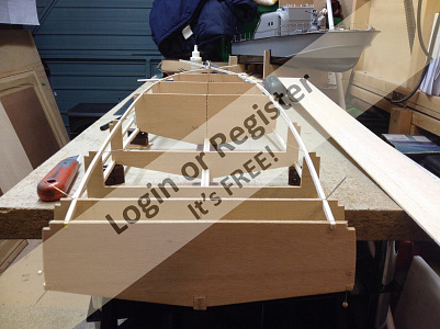
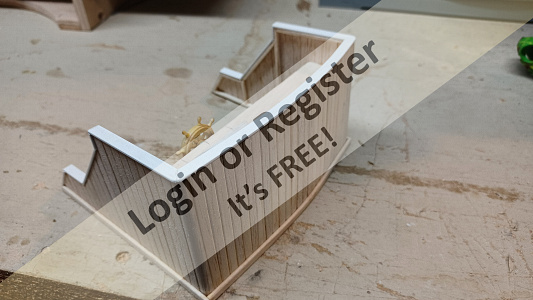
Once I had fitted the decking and hull edge stringers from bow to stern-port and starboard. I then cut and fitted the fore deck. this helped in two ways as it helped with the curve at the bow and stiffened and squared up the whole structure.
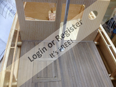
To keep the hull square and symmetrical while the cladding was in progress, the hull was clamped to the bench top with the same method as before. by using the small plastic blocks that have 2 screw holes in, there then is no chance of any movement. the deck from the 1st bulkhead forward is curved upwards so I again had to hang this front portion of the hull off the bench top as the deck aft of this point is flat. this can be seen in the 3rd photo.
My next job was cladding the hull with 1/8" x 4" balsa sheet. the bow forward of the no1 bulkhead was filled completely with solid balsa chunks and carved to shape - once the main hull was clad. To help the balsa sheet bend and set to the slight curvature of the hull bottom pins were used while the glue set. by the way the glue used was "Aliphatic resin " excellent hold and setting properties. As well as the pins I also employed several sizes of "bulldog" clips, which I've found spread the pressure over a greater area when clamping surfaces together, especially when working with softish balsa sheet
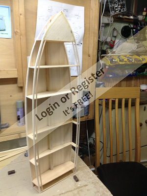
▲
⟩⟩
saxyang
Peejay
GregHiltz
Colin H
Julio
📝 orca build part4
2 years ago by 🇬🇧 Rogal118 ( Lieutenant Commander)
Lieutenant Commander)✧ 136 Views · 3 Likes · 1 Comment
Flag
💬 Add Comment
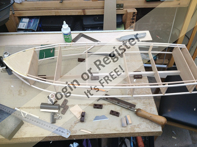
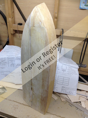
Once I had clad the hull completely, the bow section forward of the no1 bulkhead was filled in with solid balsa and carved to shape. the hull was sanded with fine grade abrasive paper to give a nice smooth finish. the deck was not fitted at this stage, making it easier to seal the inner hull.
At this stage I also fitted a ply base to mount the motor and a ply block over the keel to support the mast.
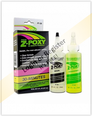
For the sealing process I used a 2 part resin as seen in photo 1, the external hull was given one coat and left to set. this sealed the wood as I brushed it on in quite a watery coat which in turn sealed and lifted the grain to some extent, this is why I left the 1st coat to set completely. I then gave the whole external surface another fine sanding to leave a good smooth surface.
the next stage was to mix some more resin and coat the outer hull once more but this time laying on some fine light weight random glass cloth. this was then stippled in using the brush bristle tips. using this method forces the resin through the glass fibre cloth to make sure I had a good bond to the hull. the resin jellifies quite quickly, 10-15 minutes, so you have to be organized and then work fast. what I found was if I had a bit of resin left I would use it to coat the inner hull and bulkheads . this way none was wasted. more resin was then mixed and a second coat of glass cloth added to the first while still tacky, this helps bond the two together. when happy all the cloth is saturated and no bubbles are present the hull was left to set.
At this stage I also fitted a ply base to mount the motor and a ply block over the keel to support the mast.
For the sealing process I used a 2 part resin as seen in photo 1, the external hull was given one coat and left to set. this sealed the wood as I brushed it on in quite a watery coat which in turn sealed and lifted the grain to some extent, this is why I left the 1st coat to set completely. I then gave the whole external surface another fine sanding to leave a good smooth surface.
the next stage was to mix some more resin and coat the outer hull once more but this time laying on some fine light weight random glass cloth. this was then stippled in using the brush bristle tips. using this method forces the resin through the glass fibre cloth to make sure I had a good bond to the hull. the resin jellifies quite quickly, 10-15 minutes, so you have to be organized and then work fast. what I found was if I had a bit of resin left I would use it to coat the inner hull and bulkheads . this way none was wasted. more resin was then mixed and a second coat of glass cloth added to the first while still tacky, this helps bond the two together. when happy all the cloth is saturated and no bubbles are present the hull was left to set.
▲
⟩⟩
quattroo
pressonreguardless
Colin H
|
💬 Re: orca build part4
2 years ago by 🇨🇦 Brightwork (
 Captain) Captain)✧ 131 Views · 1 Like
Flag
That's how I do it. I use .75 oz Unstarched cloth
▲
⟩⟩
Rogal118
|
📝 orca build part5
2 years ago by 🇬🇧 Rogal118 ( Lieutenant Commander)
Lieutenant Commander)✧ 124 Views · 6 Likes · 2 Comments
Flag
💬 Add Comment
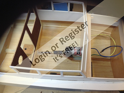
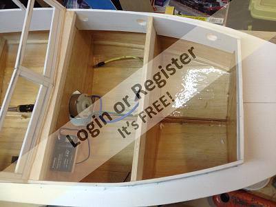
Now that the external hull construction is complete, the internal control fittings needed to be installed although they would be removed until a later date, when fitted permanently. I had already made a list and purchased the required items from various UK suppliers.
The first item I fitted was the rudder and servo, my preference for these were a "Futuba S3014" servo and a "radio active" large bladed 60mmx40mm rudder which has a brass blade. the control horn I had was a 90deg type which was modified to just a straight operating arm, it had the correct hole diameter to accept the rudder shaft so once the hole had been bored in the keel centre the outer shaft was bonded in place. the servo was positioned only 40mm away as the space was a bit tight. I coupled up the servo to the receiver and fired it up, this was mainly to centre the servo up before connecting the control rod to the two control arms. A hole was cut in the inner transom bulkhead to take the servo connector, another hole in the next bulkheads so an servo extension wire will route the wire into the battery/receiver compartment. Having satisfied myself that the set up worked to port and starboard without fouling in such a confined space, it was dismantled leaving just the outer rudder shaft in place.
The prop shaft had already been installed, just before I coated the external hull with glass fibre, it needed to be fitted then so as to line up the motor mounting plate. this way it would line up exactly with the motor shaft centre line. Though thinking about this setup lately, I would have preferred to fit a longer shaft so the motor would have been set a little further forward in the hull, in the same compartment as the batteries. My only reason for this is it falls half way in the main cabin and with it being a decent size scale boat , it would allow plenty of scope to show the scale internals. I will maybe change the internal shaft length later to push the motor another 40mm further forward!. hindsight is a wonderful thing.
▲
⟩⟩
hermank
quattroo
mturpin013
Colin H
Graham93
Julio
|
💬 Re: orca build part5
11 months ago by 🇬🇧 Rogal118 (
Lieutenant Commander)✧ 34 Views · 0 Likes
Flag
Yes it is tight, but there is enough room if you keep the rudder to one side so the arm has enough throw to give a good rudder movement.good luck.
▲
⟩⟩
No likes yet
This member will receive 1 point for every like received |
|
💬 Re: orca build part5
11 months ago by 🇬🇧 quattroo (
 Chief Petty Officer 1st Class) Chief Petty Officer 1st Class)✧ 36 Views · 1 Like
Flag
Crikey super tight we're that rudder is 👍
▲
⟩⟩
Rogal118
|
📝 orca build part6
2 years ago by 🇬🇧 Rogal118 ( Lieutenant Commander)
Lieutenant Commander)✧ 118 Views · 6 Likes · 3 Comments
Flag
💬 Add Comment
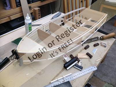
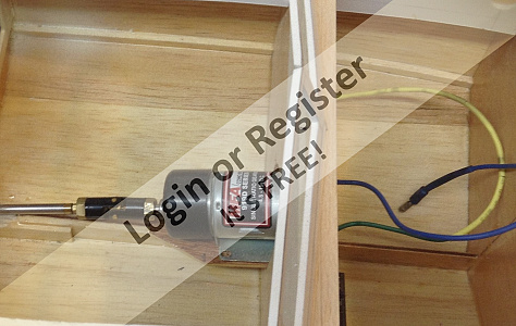
My next job was to fit the motor, this was a type I have used before and have found adequate for the job across the board. It is a "MFA540" brushed motor with a 2.5-1 gearing ratio suitable for use from 4v to 15v and coupled to a 40mm 3bladed prop, should give a nice scale chug along speed without being to fast and tearing the pond up. the motor will be run through a "hobbywing Quicrun" 1060 waterproof 60A esc. Again I have had these fitted to all my fleet and have never had any problems, either with the setting up or operation.
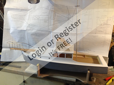
The rear decking is a nice size to work with approx. 200mmx200mm, so I decided to use some 3mm ply with planking on the top. I was a little worried at first, that gluing individual planks on the top surface would curl the ply upwards, so I sealed the underside with polyurethane clear varnish, once I had cut and fitted the deck to size. this was to be removable for access to the wiring underneath. So I set about planking the top surface of the deck using 1mmx 6mm walnut strip. now I don't know if this Type of timber is used on life size boats as I believe Teak is commonly used. My problem here was teak strip was not available and I thought that walnut looked good. two stainless washers were inlaid into the planking as seen in the photo, I also inlaid a hatch to represent the motor access.
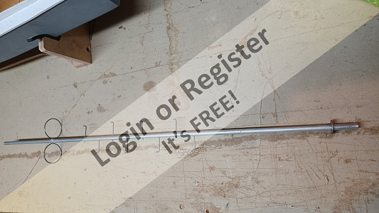
A length of aluminium tube 7mm outer dia was used for the mast, this was drilled at intervals and 1mm piano wire was inserted and araldited in place to represent the foot pegs. towards the top is a double loop band that is to support a crew member when on lookout up the mast. This was tricky to make as the piano wire is stiff and difficult to form into a circle. but in the end I was happy with my efforts and will look the part when all other fittings are added
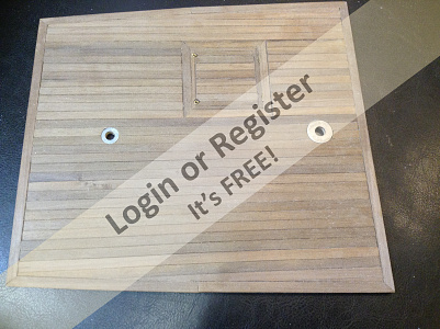
The rear decking is a nice size to work with approx. 200mmx200mm, so I decided to use some 3mm ply with planking on the top. I was a little worried at first, that gluing individual planks on the top surface would curl the ply upwards, so I sealed the underside with polyurethane clear varnish, once I had cut and fitted the deck to size. this was to be removable for access to the wiring underneath. So I set about planking the top surface of the deck using 1mmx 6mm walnut strip. now I don't know if this Type of timber is used on life size boats as I believe Teak is commonly used. My problem here was teak strip was not available and I thought that walnut looked good. two stainless washers were inlaid into the planking as seen in the photo, I also inlaid a hatch to represent the motor access.
A length of aluminium tube 7mm outer dia was used for the mast, this was drilled at intervals and 1mm piano wire was inserted and araldited in place to represent the foot pegs. towards the top is a double loop band that is to support a crew member when on lookout up the mast. This was tricky to make as the piano wire is stiff and difficult to form into a circle. but in the end I was happy with my efforts and will look the part when all other fittings are added
▲
⟩⟩
hermank
quattroo
mturpin013
pressonreguardless
Colin H
Julio
|
💬 Re: orca build part6
11 months ago by 🇬🇧 Rogal118 (
Lieutenant Commander)✧ 34 Views · 0 Likes
Flag
Hi there. Just a point that has occured to me in my blog regarding the prop shaft and the positioning of the motor, as it is one of the early build decitions i did not realise that the motor fits in the middle of the main cabin. If at a later date you want to fit out the cabin as i have done. I had to fit a longer prop shaft so as to move the motor out of sight into the forward cabin. I did not wish to disturb the outer shaft as it was fixed to good. These thoughts might be worth pondering over to save messing about later as i did. Hindsight is a wonderful thing
▲
⟩⟩
No likes yet
This member will receive 1 point for every like received |
|
Login To
Remove Ads 💬 Re: orca build part6
2 years ago by 🇬🇧 Rogal118 (
Lieutenant Commander)✧ 114 Views · 1 Like
Flag
Yes it will be sealed, I prefere to use matt polyurethane. Seals but looks well scrubed in, expecially for a work boat were a high gloss finish would not look right. Thanks for the comment.
▲
⟩⟩
pressonreguardless
|
|
💬 Re: orca build part6
2 years ago by 🇺🇸 pressonreguardless (
 Rear Admiral) Rear Admiral)✧ 98 Views · 1 Like
Flag
The Walnut looks great. Shouldn't be a problem as long as you seal it.
Walnut is not used on full sized boats as it is not rot resistant. Trev ▲
⟩⟩
Rogal118
|
📝 Orca build part7
2 years ago by 🇬🇧 Rogal118 ( Lieutenant Commander)
Lieutenant Commander)✧ 104 Views · 5 Likes
Flag
💬 Add Comment
With the rear deck planking complete, I was happy with the wiring runs and access to the radio gear, my thoughts turned to closing the bow and side decking. For some reason even now, I never felt comfortable with the tops being either ply or balsa. With having to seal them and rub down, then seal again, the same with the superstructure and then finally paint. Now I know this has been the tried and tested method with modellers for years and very good results can be achieved, but just lately I have found using plastic card of various thicknesses, gives a lot finer and sharper detail. With this in mind I purchased a couple of sheets of 3mm white foam board, large enough to cut the whole deck top from bow to stern in one piece, albeit it was split along the centre line on the bow deck. Then cut roughly to shape and tacked into position I then scribed around the hull and inner deck. the two halves were then cut carefully to size but leaving an extra 1mm over hanging the outer hull.
The reason this was done, can be seen in the first photo, a cross section of my hull that describes why. I have found in my previous builds getting a nice neat edge between the hull and deck is critical for a good looking model so this is my solution. By leaving the decking protruding by 1mm an "I" section plastic beam ready painted can be fitted at a later stage when the model is painted and nearly complete, this will leave a sharp contrast line between deck and hull. one other bonus I find is that if you strip the centre core multi wires from a length of landline type telephone wire it leaves a flexible plastic tube that can be bonded into the outer edge of the "I" beam to form a soft and flexible buffer strip to the deck edge.
Now I know the actual ORCA does not have this feature, but a bit of modellers licence helps protect the model from the odd bump pond side.
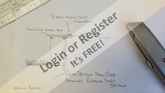
▲
⟩⟩
mturpin013
Scratchbuilder
Colin H
Graham93
Julio
📝 orca build part8
2 years ago by 🇬🇧 Rogal118 ( Lieutenant Commander)
Lieutenant Commander)✧ 101 Views · 8 Likes · 1 Comment
Flag
💬 Add Comment
Every now and then during a build I tend to get a modellers block, were I can`t decide how to proceed next, so the construction grinds to a halt. It is at times like this when I look at the extras and fittings that are required to embellish the model.
This next blog deals with one of those times, Now I must also apologise to some fellow modellers who have seen my earlier topic showing this particular subject, but at the time I was so delighted with the results I wanted to make it a special topic.
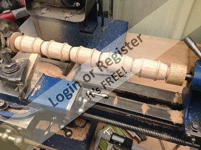
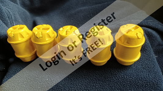
This part of the build deals with the 5 barrels on the front cabin top, that are used in the film to keep the sharks buoyant once they have been harpooned, as they are roped to the harpoon just before the shot is taken.
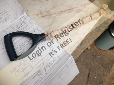
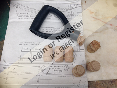
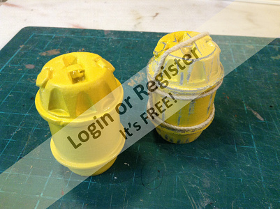
These parts can be purchased commercially at around £4-5 pound each, which I was not prepared to do. so I required a piece of 1-1/4" dowel which was expensive to buy and in a 6 foot length, too much for this project. When in a stroke of good look I came across a broken shovel handle and shaft, just the job! and the right width and length. The handle was sawn off and the shaft fitted in my lathe, as can be seen in the photos I turned all 5 together then split them into individual barrels. Using my pillar drill I hollowed the inside from the underside to take some of the weight off, at the same time using the end mill to notch the top of the barrels to make them more lifelike. A slot was routed across the top and a handle fitted. All 5 were then sprayed grey a couple of times, left to dry then a couple of coats of bright yellow. Once this had set I sanded and scuffed up the yellow paint down to the grey to give a well worn, knocked about look, as can be seen in the 5th photo. I purchased a roll of 1mm rigging cord in white to use for the rope around the barrels, also in photo 5.
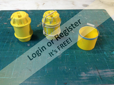
During this period I also had a brain wave when taking the top off the grey spray can, this looked just right to make a scale "chum bucket" which after a bit of fiddling the result can be seen in photo 6 next to the finished barrel
I must say I revel in making parts out of bottle tops and other parts found in the cosmetic shelves, and have been known to buy a couple of bottles of shampoo just for the lids to make hatches for my brave borderer in the past.
This next blog deals with one of those times, Now I must also apologise to some fellow modellers who have seen my earlier topic showing this particular subject, but at the time I was so delighted with the results I wanted to make it a special topic.
This part of the build deals with the 5 barrels on the front cabin top, that are used in the film to keep the sharks buoyant once they have been harpooned, as they are roped to the harpoon just before the shot is taken.
These parts can be purchased commercially at around £4-5 pound each, which I was not prepared to do. so I required a piece of 1-1/4" dowel which was expensive to buy and in a 6 foot length, too much for this project. When in a stroke of good look I came across a broken shovel handle and shaft, just the job! and the right width and length. The handle was sawn off and the shaft fitted in my lathe, as can be seen in the photos I turned all 5 together then split them into individual barrels. Using my pillar drill I hollowed the inside from the underside to take some of the weight off, at the same time using the end mill to notch the top of the barrels to make them more lifelike. A slot was routed across the top and a handle fitted. All 5 were then sprayed grey a couple of times, left to dry then a couple of coats of bright yellow. Once this had set I sanded and scuffed up the yellow paint down to the grey to give a well worn, knocked about look, as can be seen in the 5th photo. I purchased a roll of 1mm rigging cord in white to use for the rope around the barrels, also in photo 5.
During this period I also had a brain wave when taking the top off the grey spray can, this looked just right to make a scale "chum bucket" which after a bit of fiddling the result can be seen in photo 6 next to the finished barrel
I must say I revel in making parts out of bottle tops and other parts found in the cosmetic shelves, and have been known to buy a couple of bottles of shampoo just for the lids to make hatches for my brave borderer in the past.
▲
⟩⟩
hermank
mturpin013
Scratchbuilder
stevedownunder
Colin H
Commodore-H
pressonreguardless
Julio
|
💬 Re: orca build part8
2 years ago by 🇺🇸 pressonreguardless (
Rear Admiral)✧ 83 Views · 2 Likes
Flag
Excellent Repurposing👍👍
Waste Not Want Not! They Look Great! Trev ▲
⟩⟩
Commodore-H
Rogal118
|
📝 orca build part9
2 years ago by 🇬🇧 Rogal118 ( Lieutenant Commander)
Lieutenant Commander)✧ 91 Views · 10 Likes · 1 Comment
Flag
💬 Add Comment
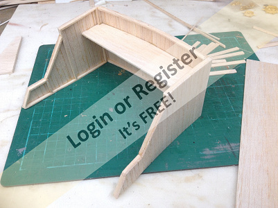
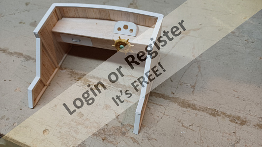
My next part to construct was the flying bridge that sits on the main wheelhouse roof. Viewing the stills from the original film gave an insight into a lot more detail for this area than can be shown on the plans. With this in mind I decided to make the 2 side frames from 2mm x 4mm balsa strip. then the front was framed up using similar section, but because it has a curve built in, I cut the top and bottom frame rails from sheet balsa and joined them together with the vertical frame sides. The idea behind making a frame first was that I could then vertical plank the external face. to do this I used balsa strip 1mm x 5mm but before gluing in place the top 2 edges of this strip were rounded off, then when butted next to each other it gave an impression of a planked look.
The three sides were joined with a balsa corner post, that was rounded on the corner. The whole bridge top edge was then capped with a plastic strip to give some sharpness to the construction, as I have said before balsa can be a little "hairy" even when sealed and painted. These two surface finishes can be seen in the 3rd photo. A skirting was added to the base of the bridge, as was an internal console table which in fact helped to stabilize the whole construction. On to this was added the ships wheel and control panel, there are other instruments to fit but will be fitted at a later date when sourced. An intermediate rail is to be added approx. 2/3rds up to give visual similarity to the original.
One of my next jobs, that I've been pondering over is how to make the set of jaws that decorate the front of the bridge (photo 5), shot taken of a fishmongers window on a recent trip to Whitby, North Yorkshire. I purchased a tube of modelling putty that I think I can use to mould the jaws from and then add white plastic teeth. We will see how fiddly/successful this is soon, watch this space for a future blog.
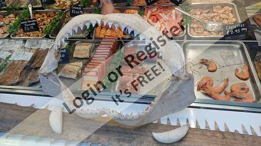
▲
⟩⟩
hermank
quattroo
pressonreguardless
jbkiwi
Peejay
mturpin013
Rowen
Rookysailor
Colin H
Julio
|
💬 Re: orca build part9
2 years ago by 🇬🇧 mturpin013 (
 Admiral) Admiral)✧ 74 Views · 3 Likes
Flag
I've only just caught up with the site after an absence and just read your blog from the beginning, Walnut looks great when finished I did all the deck of my Police boat in it and its a nice wood to work with you can achieve some fine detail with this hard wood.
altogether a great blog and look forward to reading the rest ▲
⟩⟩
hermank
Scratchbuilder
Rogal118
|
📝 orca build part10
2 years ago by 🇬🇧 Rogal118 ( Lieutenant Commander)
Lieutenant Commander)✧ 74 Views · 6 Likes · 2 Comments
Flag
💬 Add Comment
Now the flying bridge is 90% complete it has been put to one side, I tend to work like this, jumping from component to component. I seem to get better inspiration this way and it keeps the build from going stale, and keeping the old grey cells turning over, as there is always another challenge with the next component waiting to be made.
So picking up from earlier in the build I went back to making the wheelhouse and forward cabin. Looking at earlier photos you may have noticed the sides of the wheelhouse in place, including the front wind shield and cabin sides, again made and left until later in the build, otherwise the blog would jump all over the place.
These side walls were again made using 2mm foam board, I tried building the window frames, etc. in balsa but they were too fragile. The wheelhouse, cabin side and the aft deck firring were then able to be produced in one piece, which was not possible with balsa. I intend to frame the window openings with mahogany strip later when the superstructure is painted.The internal cabin finish will also be dark stained paneling, another idea tumbling around my head for a later date.
I acquired 6 brass 15mm portholes so at this stage cut the holes to accept these, hope i remembered were they are, come the day to fit!.
Foam board was used also to make the wheelhouse and cabin roof, I backed up the roof panels with pine strip to stiffen and help locate, as these are removable for access. Also made was the bow bulwarks which extend only as far as half way along the forward cabin, I suppose these act as a splash guard in this design of craft, fixing these in place also helped with the positioning of the pulpit floor and pulpit handrails
▲
⟩⟩
hermank
saxyang
mturpin013
Madwelshman
pressonreguardless
Julio
|
💬 Re: orca build part10
2 years ago by 🇬🇧 Rogal118 (
Lieutenant Commander)✧ 74 Views · 2 Likes
Flag
Thanks for your interest.
The white foam board that I have is very light similar to balsa and I find easier to cut as the blade does not want to follow the grain as with balsa. The surface is very slightly textured. Well more of a matt finish, not smooth like plasticard. It will take a steady curve, and bonds well with supa glue,2part resin etc.it has its limitations but all materials do. And I have found it takes spray can paint well without primers and after a couple of coats the slightly textured surface is nice and smooth ▲
⟩⟩
hermank
Madwelshman
|
|
💬 Re: orca build part10
2 years ago by 🇺🇸 pressonreguardless (
Rear Admiral)✧ 54 Views · 1 Like
Flag
Coming along nicely.
Do you have to treat/coat the foam board? Trev ▲
⟩⟩
Rogal118
|


Login To
Remove Ads
Remove Ads