Here's the history bit so pay attention...
Many years ago as a boy in the fifth year of my north London secondary school, circa 1971, our woodwork class was given the option to make something of our own choice.
Having mastered the majority of joints, wood turning, finishing techniques and the making of table lamps, stools and bookshelves etc. this seemed a good idea, so myself and a fellow classmate and model making chum asked if we could construct a model boat.
The teacher, on hearing that it was to be from a kit and not from scratch was a little surprised but agreed.
So my friend and I jointly invested about 20 quid in an Aerokits 34.5 inch RAF Crash Tender from Blunts' model shop in Mill Hill (long since gone like many others) and we set about construction during lesson time and sometimes at break times.
I recall we used "Cascamite" to glue it all together on the advice of the woodwork teacher because neither 'Scotch' glue nor PVA was suited to marine construction.
Good progress was made over the course of our last year at school but it was never fully completed, only requiring painting, running gear and detailing.
My friend decided that he needed to withdraw from the project as he was enrolling in a college away from home to study for a career in the merchant navy and I agreed to buy out his share and continue with the project.
And so it was that I carried on with the painting and installing the running gear which consisted of a 1.5 cc marine diesel engine, water pickup, prop shaft and rudder and a MacGregor radio system with a stick for steering and a single button for speed control.
The engine and radio came from Michael's Models in Finchley (also long gone) for £20 as my elder brother, who had started a Saturday job there, was able to get a staff discount for me.
The diesel engine was noisy and smelly and a pig to start with a leather thong around the flywheel and I decided to abandon this means of propulsion (I foolishly ran it for slightly too long 'dry' and melted the soldering around the brass water jacket!).
By now I had graduated from my part time job in Woolies to an engineering apprentice with Post Office Telephones and my new income of 20 quid per week could support my modelling and electronics hobbies after my contribution to the household for my keep.
So off to the model shop to buy a Taycol Supermarine electric motor, two 12v volt lead acid batteries and a suitable charger.
The diesel came out and was sold on Exchange & Mart and the mount and coupling re-made to accommodate the new Taycol motor.
What an improvement that was!
I can't remember now what speed controller or servo I used but whatever it was did the job, and it went like the clappers on Friary Park boating lake (also long since gone) even though the radio control system was a bit crude with the non-proportional steering and 'blip' throttle control.
The boating took a back seat when I acquired my driving licence and my first car (a rusty old Cortina Mk 1) and I also got involved in sound recording for radio.
I decided to sell the boat and bits for £60 through Exchange & Mart and bought an Akai 4000DS tape recorder and a 'Chilton' audio mixer, built a home studio and along with a good mate of mine started making radio commercials for the new commercial radio stations including London's Capital Radio.
We even won a 'Campaign' advertising award for one of our efforts! And so after several years as a 'phone engineer I moved into professional recording for A/V and broadcast and then into TV production.
Fast forward to today.
Semi-retired with grand kids and with more free time on my hands I still had an interest in model making so in Jan 2016 went to the Model Engineer exhibition at nearby 'Ally Pally'.
It was there that I saw an RAF crash tender just like the one I built all those years ago and got into conversation with the chap on the stand.
This re-ignited my model making interests and I researched the hobby and that model in particular.
Here's the history bit so pay attention...
Many years ago as a boy in the fifth year of my north London secondary school, circa 1971, our woodwork class was given the option to make something of our own choice.
Having mastered the majority of joints, wood turning, finishing techniques and the making of table lamps, stools and bookshelves etc. this seemed a good idea, so myself and a fellow classmate and model making chum asked if we could construct a model boat.
The teacher, on hearing that it was to be from a kit and not from scratch was a little surprised but agreed.
So my friend and I jointly invested about 20 quid in an Aerokits 34.5 inch RAF Crash Tender from Blunts' model shop in Mill Hill (long since gone like many others) and we set about construction during lesson time and sometimes at break times.
I recall we used "Cascamite" to glue it all together on the advice of the woodwork teacher because neither 'Scotch' glue nor PVA was suited to marine construction.
Good progress was made over the course of our last year at school but it was never fully completed, only requiring painting, running gear and detailing.
My friend decided that he needed to withdraw from the project as he was enrolling in a college away from home to study for a career in the merchant navy and I agreed to buy out his share and continue with the project.
And so it was that I carried on with the painting and installing the running gear which consisted of a 1.5 cc marine diesel engine, water pickup, prop shaft and rudder and a MacGregor radio system with a stick for steering and a single button for speed control.
The engine and radio came from Michael's Models in Finchley (also long gone) for £20 as my elder brother, who had started a Saturday job there, was able to get a staff discount for me.
The diesel engine was noisy and smelly and a pig to start with a leather thong around the flywheel and I decided to abandon this means of propulsion (I foolishly ran it for slightly too long 'dry' and melted the soldering around the brass water jacket!).
By now I had graduated from my part time job in Woolies to an engineering apprentice with Post Office Telephones and my new income of 20 quid per week could support my modelling and electronics hobbies after my contribution to the household for my keep.
So off to the model shop to buy a Taycol Supermarine electric motor, two 12v volt lead acid batteries and a suitable charger.
The diesel came out and was sold on Exchange & Mart and the mount and coupling re-made to accommodate the new Taycol motor.
What an improvement that was!
I can't remember now what speed controller or servo I used but whatever it was did the job, and it went like the clappers on Friary Park boating lake (also long since gone) even though the radio control system was a bit crude with the non-proportional steering and 'blip' throttle control.
The boating took a back seat when I acquired my driving licence and my first car (a rusty old Cortina Mk 1) and I also got involved in sound recording for radio.
I decided to sell the boat and bits for £60 through Exchange & Mart and bought an Akai 4000DS tape recorder and a 'Chilton' audio mixer, built a home studio and along with a good mate of mine started making radio commercials for the new commercial radio stations including London's Capital Radio.
We even won a 'Campaign' advertising award for one of our efforts! And so after several years as a 'phone engineer I moved into professional recording for A/V and broadcast and then into TV production.
Fast forward to today.
Semi-retired with grand kids and with more free time on my hands I still had an interest in model making so in Jan 2016 went to the Model Engineer exhibition at nearby 'Ally Pally'.
It was there that I saw an RAF crash tender just like the one I built all those years ago and got into conversation with the chap on the stand.
This re-ignited my model making interests and I researched the hobby and that model in particular.
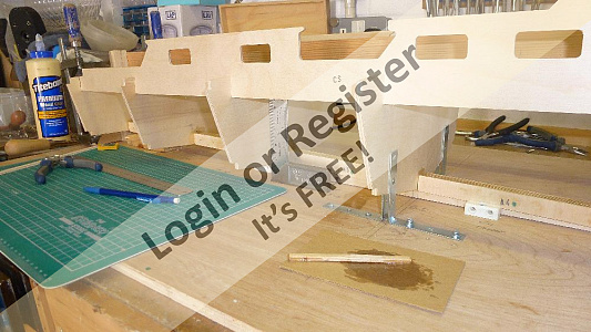
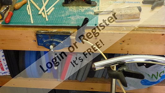
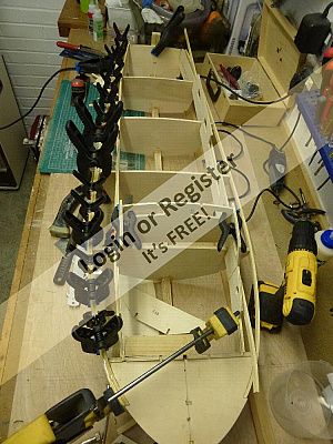
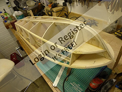
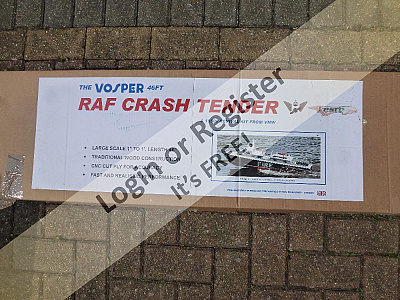
In May an eBay item caught my attention, it was a 46" unbuilt and complete Crash tender by Vintage Model Works and my bidding secured it for just under £200.
I drove to Gt Yarmouth to collect it from the seller as I did not want to entrust it's delivery to the likes of Parcelfarce or similar.
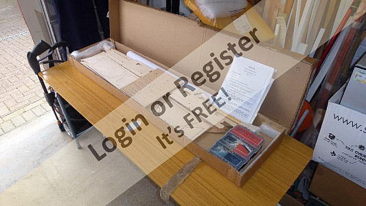
The kit was indeed complete and in mint condition with fittings, transfers and plans/instructions.
The documents were dated April 2012 and the recommended motor, ESC & batteries etc. were by now obsolete/unavailable so I put call in to Mike Cummings at Vintage Model Works who answered a few questions about the kit and contents, he in turn put me in touch with a very helpful chap by the name of Alan Holmes who recommended a motor, ESC and battery combination from Hobbyking and Component Shop that were more suitable.
I would like to thank them both for their advice and guidance on the construction of the model as it has proved invaluable to me.
Mike also suggested a build blog on this site would be appreciated by others too which I am happy to start now.
I have documented the construction in photographs since the start in Mid May and will continue until it is completed but I decided not to start the blog until I was well into the build and had sufficient material to post regularly.
I am now at the painting stage and slowly nearing completion......
[{"id":"1476736003","url":"https:\/\/model-boats.com\/media\/1476736003\/l","thumbUrl":"https:\/\/model-boats.com\/media\/1476736003\/s","name":"1476736003","caption":""},{"id":"1476633254","url":"https:\/\/model-boats.com\/media\/1476633254\/l","thumbUrl":"https:\/\/model-boats.com\/media\/1476633254\/s","name":"1476633254","caption":""},{"id":"1476633350","url":"https:\/\/model-boats.com\/media\/1476633350\/l","thumbUrl":"https:\/\/model-boats.com\/media\/1476633350\/s","name":"1476633350","caption":""},{"id":"1476736118","url":"https:\/\/model-boats.com\/media\/1476736118\/l","thumbUrl":"https:\/\/model-boats.com\/media\/1476736118\/s","name":"1476736118","caption":""}]
In May an eBay item caught my attention, it was a 46" unbuilt and complete Crash tender by Vintage Model Works and my bidding secured it for just under £200.
I drove to Gt Yarmouth to collect it from the seller as I did not want to entrust it's delivery to the likes of Parcelfarce or similar.
The kit was indeed complete and in mint condition with fittings, transfers and plans/instructions.
The documents were dated April 2012 and the recommended motor, ESC & batteries etc. were by now obsolete/unavailable so I put call in to Mike Cummings at Vintage Model Works who answered a few questions about the kit and contents, he in turn put me in touch with a very helpful chap by the name of Alan Holmes who recommended a motor, ESC and battery combination from Hobbyking and Component Shop that were more suitable.
I would like to thank them both for their advice and guidance on the construction of the model as it has proved invaluable to me.
Mike also suggested a build blog on this site would be appreciated by others too which I am happy to start now.
I have documented the construction in photographs since the start in Mid May and will continue until it is completed but I decided not to start the blog until I was well into the build and had sufficient material to post regularly.
I am now at the painting stage and slowly nearing completion......
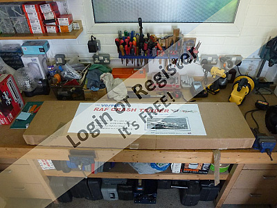
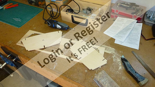
Checked the kit contents against the supplied list and it's all complete including the white metal fittings, windows and frames and transfers.
The building instructions and diagrams are less than concise but a good enough as a guide.
Had to buy some new modelling tools, saws, knives etc.
Luckily I already had a Dremmel with a good range of cutting and drilling accessories.
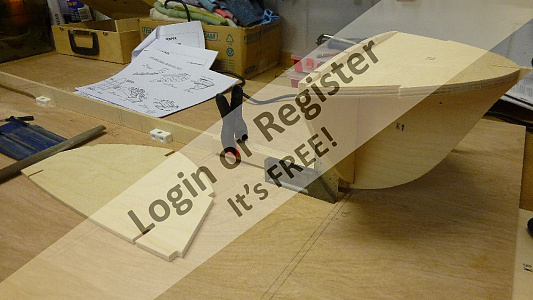
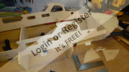
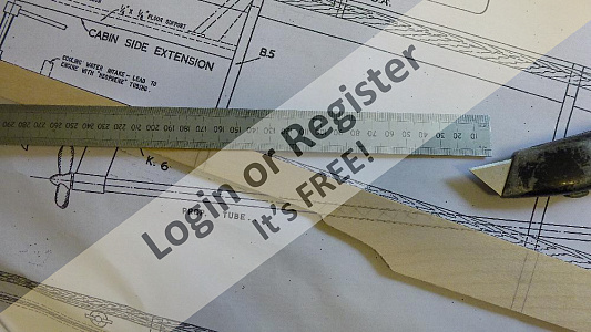
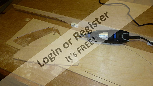
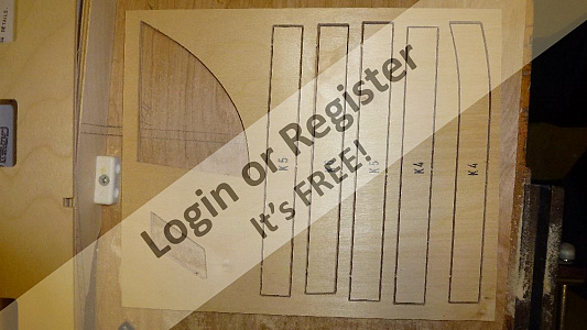
Aliphatic and epoxy adhesives and brass pins are on order so meanwhile I cut out the keel and bulkheads from their respective panels and dry fit them to the building board and jig to see how accurate and square the hull will be.
[{"id":"1476908843","url":"https:\/\/model-boats.com\/media\/1476908843\/l","thumbUrl":"https:\/\/model-boats.com\/media\/1476908843\/s","name":"1476908843","caption":""},{"id":"1476908885","url":"https:\/\/model-boats.com\/media\/1476908885\/l","thumbUrl":"https:\/\/model-boats.com\/media\/1476908885\/s","name":"1476908885","caption":""},{"id":"1476908987","url":"https:\/\/model-boats.com\/media\/1476908987\/l","thumbUrl":"https:\/\/model-boats.com\/media\/1476908987\/s","name":"1476908987","caption":""},{"id":"1476909042","url":"https:\/\/model-boats.com\/media\/1476909042\/l","thumbUrl":"https:\/\/model-boats.com\/media\/1476909042\/s","name":"1476909042","caption":""}]
Checked the kit contents against the supplied list and it's all complete including the white metal fittings, windows and frames and transfers.
The building instructions and diagrams are less than concise but a good enough as a guide.
Had to buy some new modelling tools, saws, knives etc.
Luckily I already had a Dremmel with a good range of cutting and drilling accessories.
Aliphatic and epoxy adhesives and brass pins are on order so meanwhile I cut out the keel and bulkheads from their respective panels and dry fit them to the building board and jig to see how accurate and square the hull will be.
Hi figtree7nts.
The parts are cut with a CNC router which seems to give very consistent and accurate cuts and I have not needed to 'ease' any of the interlocking parts.
I recall that the Aerokits 34.5 inch model I built all those years ago needed a little work to make the parts fit, they may have been die cut.
It's also very good quality ply and obeche wood in the kit.
Robbob
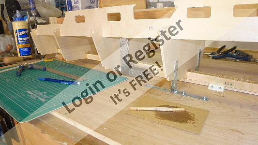
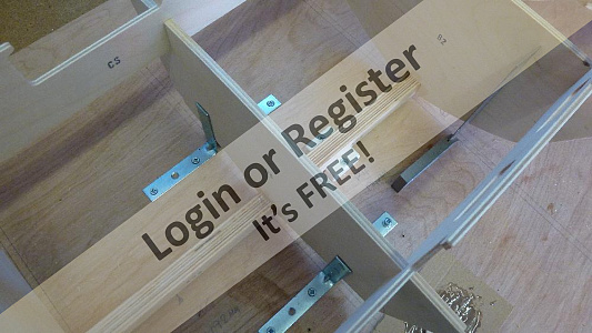
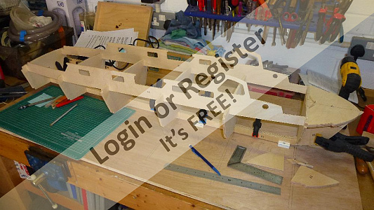
Dry fitted all the keel parts and bulkheads and transom, the jig has supports at the front and rear to secure the bow and transom in perfect alignment and metal 'L' bracket to keep the bulkheads vertical and square.
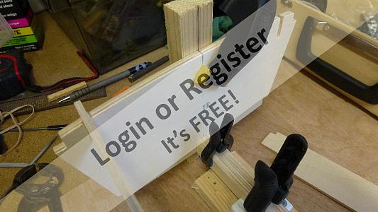
The cabin sides lock everything in place but will require some shallow cuts on the inner surfaces to bend properly without breaking.
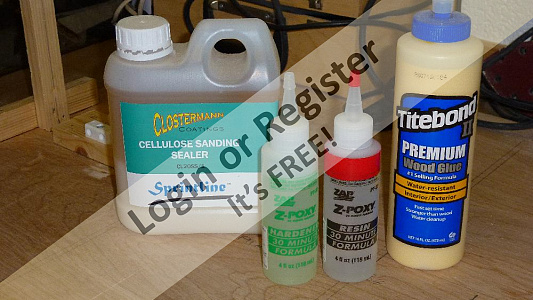
I'll be using Titebond 11 and Zpoxy 30 minute epoxy as recommended, adhesives have come a long way since my last boat build when mixing 'Cascamite' up to the right consistency was a bit of a pain as I recall.
When the propshaft arrives I can cut the keel to accommodate it and start glueing and clamping it all together.
I have bought lots of clamps to hold the bits while the glue dries, it seems you can't have too many of those !
[{"id":"1477149726","url":"https:\/\/model-boats.com\/media\/1477149726\/l","thumbUrl":"https:\/\/model-boats.com\/media\/1477149726\/s","name":"1477149726","caption":""},{"id":"1477149764","url":"https:\/\/model-boats.com\/media\/1477149764\/l","thumbUrl":"https:\/\/model-boats.com\/media\/1477149764\/s","name":"1477149764","caption":""},{"id":"1477149807","url":"https:\/\/model-boats.com\/media\/1477149807\/l","thumbUrl":"https:\/\/model-boats.com\/media\/1477149807\/s","name":"1477149807","caption":""},{"id":"1477149871","url":"https:\/\/model-boats.com\/media\/1477149871\/l","thumbUrl":"https:\/\/model-boats.com\/media\/1477149871\/s","name":"1477149871","caption":""}]
Dry fitted all the keel parts and bulkheads and transom, the jig has supports at the front and rear to secure the bow and transom in perfect alignment and metal 'L' bracket to keep the bulkheads vertical and square.
The cabin sides lock everything in place but will require some shallow cuts on the inner surfaces to bend properly without breaking.
I'll be using Titebond 11 and Zpoxy 30 minute epoxy as recommended, adhesives have come a long way since my last boat build when mixing 'Cascamite' up to the right consistency was a bit of a pain as I recall.
When the propshaft arrives I can cut the keel to accommodate it and start glueing and clamping it all together.
I have bought lots of clamps to hold the bits while the glue dries, it seems you can't have too many of those !
Hi onetenor.
Good suggestions but...
steaming works extremely well for gentle curves and I have used this method very successfully to form the hull skins and strakes.
In this case the cabin sides need to bend quite sharply in a couple of places on each side so the 'vee' cuts allows the wood to do this without the fibres of the outer ply tearing or the ply snapping. Not sure that I'd want to dunk the wood in vinegar or ammonia though 😯
Thanks.
Robbob
Vinegar etc is fine once dried out and allows for quite sharp bends Steaming also is good if steamed long enough. However V cuts are very good too .Good luck with the build it looks good so far . John
Glue, pins and sanding sealer at the ready.
I have put the 'vee' cuts in the cabin sides to allow for the sharp bends and also where the wheelhouse window needs to bend to meet the roof, the rear cockpit sides have also been glued to the rear of the cabin sides.
The propshaft slot has been cut, the false keels will also be pinned to the main keel with 15mm brass panel pins.

[{"id":"1477229871","url":"https:\/\/model-boats.com\/media\/1477229871\/l","thumbUrl":"https:\/\/model-boats.com\/media\/1477229871\/s","name":"1477229871","caption":""},{"id":"1477229905","url":"https:\/\/model-boats.com\/media\/1477229905\/l","thumbUrl":"https:\/\/model-boats.com\/media\/1477229905\/s","name":"1477229905","caption":""},{"id":"1477229947","url":"https:\/\/model-boats.com\/media\/1477229947\/l","thumbUrl":"https:\/\/model-boats.com\/media\/1477229947\/s","name":"1477229947","caption":""},{"id":"1477230459","url":"https:\/\/model-boats.com\/media\/1477230459\/l","thumbUrl":"https:\/\/model-boats.com\/media\/1477230459\/s","name":"1477230459","caption":""}]
Glue, pins and sanding sealer at the ready.
I have put the 'vee' cuts in the cabin sides to allow for the sharp bends and also where the wheelhouse window needs to bend to meet the roof, the rear cockpit sides have also been glued to the rear of the cabin sides.
The propshaft slot has been cut, the false keels will also be pinned to the main keel with 15mm brass panel pins.
Happy that keel and bulkheads fit square and true so they can now all be glued and pinned using the 30 minute epoxy.
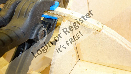
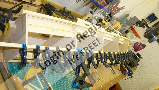
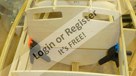
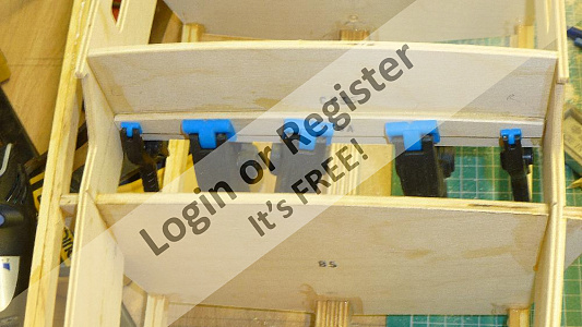
I have decided to chamfer the keel parts particularly at the bow, parts K2, K3 and the chine formers, to the approximate angles where required before assembly as it's easier to do at this stage while they are off the keel and they can be lightly trimmed and shaped to their final angles later. Once all the false rebates are fitted to the keel it is slotted into the jig and the bulkheads glued and assembled on the keel, the metal brackets ensure that it's all kept true and square. Brass pins in pre drilled holes and lots of clamps hold the parts firmly while the epoxy sets.
The Cabin sides are dry fitted to lock everything in place.
[{"id":"1477651188","url":"https:\/\/model-boats.com\/media\/1477651188\/l","thumbUrl":"https:\/\/model-boats.com\/media\/1477651188\/s","name":"1477651188","caption":""},{"id":"1477651241","url":"https:\/\/model-boats.com\/media\/1477651241\/l","thumbUrl":"https:\/\/model-boats.com\/media\/1477651241\/s","name":"1477651241","caption":""},{"id":"1477651290","url":"https:\/\/model-boats.com\/media\/1477651290\/l","thumbUrl":"https:\/\/model-boats.com\/media\/1477651290\/s","name":"1477651290","caption":""},{"id":"1477651335","url":"https:\/\/model-boats.com\/media\/1477651335\/l","thumbUrl":"https:\/\/model-boats.com\/media\/1477651335\/s","name":"1477651335","caption":""}]
Happy that keel and bulkheads fit square and true so they can now all be glued and pinned using the 30 minute epoxy.
I have decided to chamfer the keel parts particularly at the bow, parts K2, K3 and the chine formers, to the approximate angles where required before assembly as it's easier to do at this stage while they are off the keel and they can be lightly trimmed and shaped to their final angles later. Once all the false rebates are fitted to the keel it is slotted into the jig and the bulkheads glued and assembled on the keel, the metal brackets ensure that it's all kept true and square. Brass pins in pre drilled holes and lots of clamps hold the parts firmly while the epoxy sets.
The Cabin sides are dry fitted to lock everything in place.

Hi Russell
I assume that you are referring to bending the stringers and skins?
There's no need to be worried, the ply skins respond very well to heating with a hot air gun (electric paint stripper) and the obeche stringers, if well steamed, bend fairly easily too.
Scratch that itch and buy the kit, you won't regret it.
Robbob.😁
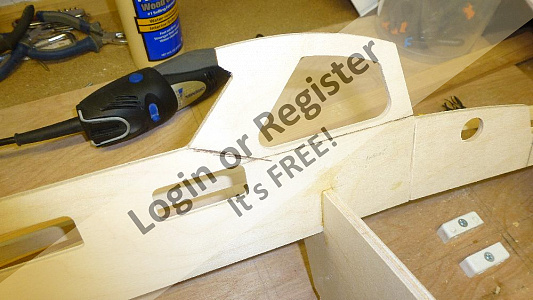
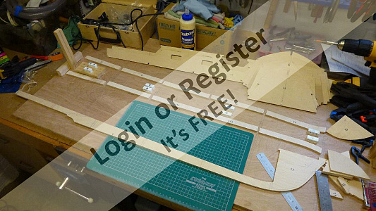
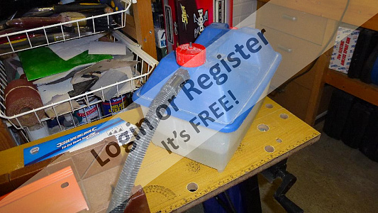
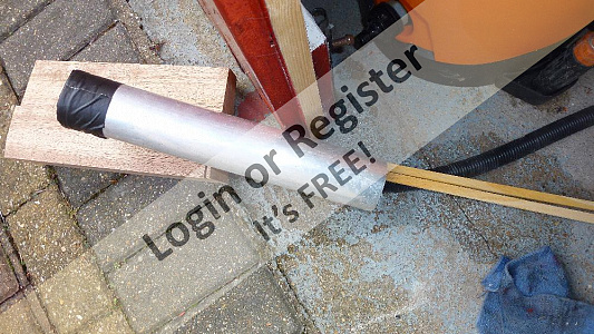
The cabin sides are now glued to the assembly and checked for square and left to dry while I dig out the wallpaper steamer in preparation for steaming the gunwhale stringers. I have a length of aluminium tubing that is ideal for a steaming tube, one end can be sealed using some duct tape and the length of the tube is sufficient to take the strakes over distance that they need to be formed.
The outlet tube of the steamer is long enough to reach outside to prevent condensation inside the workshop and stop my glasses from steaming up too !
About 15 minutes is sufficient to soften the wood and make it very pliable and when ready they are placed in the bench vice and bent to a curvature greater than required so that when they are cold they relax to approximately the right amount. The stringers are actually laminated from two pieces and the inner pieces are fitted first on each side so that the assembly doesn't twist, these are epoxied and pinned into position and lots of clamps used to hold it all together. At all stages the assembly is checked for squareness.
The process is repeated for the outer lamination of the gunwhale stringers, and so far I haven't managed to snap anything or scald myself !
[{"id":"1477757967","url":"https:\/\/model-boats.com\/media\/1477757967\/l","thumbUrl":"https:\/\/model-boats.com\/media\/1477757967\/s","name":"1477757967","caption":""},{"id":"1477758036","url":"https:\/\/model-boats.com\/media\/1477758036\/l","thumbUrl":"https:\/\/model-boats.com\/media\/1477758036\/s","name":"1477758036","caption":""},{"id":"1477758069","url":"https:\/\/model-boats.com\/media\/1477758069\/l","thumbUrl":"https:\/\/model-boats.com\/media\/1477758069\/s","name":"1477758069","caption":""},{"id":"1477758090","url":"https:\/\/model-boats.com\/media\/1477758090\/l","thumbUrl":"https:\/\/model-boats.com\/media\/1477758090\/s","name":"1477758090","caption":""}]
The cabin sides are now glued to the assembly and checked for square and left to dry while I dig out the wallpaper steamer in preparation for steaming the gunwhale stringers. I have a length of aluminium tubing that is ideal for a steaming tube, one end can be sealed using some duct tape and the length of the tube is sufficient to take the strakes over distance that they need to be formed.
The outlet tube of the steamer is long enough to reach outside to prevent condensation inside the workshop and stop my glasses from steaming up too !
About 15 minutes is sufficient to soften the wood and make it very pliable and when ready they are placed in the bench vice and bent to a curvature greater than required so that when they are cold they relax to approximately the right amount. The stringers are actually laminated from two pieces and the inner pieces are fitted first on each side so that the assembly doesn't twist, these are epoxied and pinned into position and lots of clamps used to hold it all together. At all stages the assembly is checked for squareness.
The process is repeated for the outer lamination of the gunwhale stringers, and so far I haven't managed to snap anything or scald myself !
Hi Boatshed.
I'm actually in north west London, Mill Hill/Hendon and there are no local boating lakes remaining.
The nearest may well be St.Albans or Stevenage, also there are no model clubs or societies that I am aware of in my area which is a shame as a club membership and the resulting breadth of knowledge and experience would be very welcome.
Also, Clapham is 'sarf' london and there be demons!
No disrespect to south London members. 😀
Robbob
I live in Darenth on the edge of Dartford, its a bit of a trip but its a great pond. I could go out to Maidstone as well, that's a good pond and if you want to use ic then its a Saturday job for those. St Albans or Stevenage is a fair old run from you.
The chine stringers are steamed and formed in the same manner as the gunwhale stringer, they are also laminated with the first set into a notch in the chine former. The bulkhead B1 needs to be bevelled so that the stringer lies flat in the notch. The stringers were drilled with a pin drill to prevent any splitting and epoxied and pinned to the chine former and bulkheads from fore to aft. The second lamination is done in the same way but this is glued and clamped with very few pins so that the stringer can be shaped to the bulkhead profile with no pins in the way, any pins used were punched into the lamination.
Next I fitted the deck stringers that go between the bulkheads and fixed to the cabin sides, these are to support the decks, these are just glued and clamped.
All the stringers and keel formers were then planed and sanded to the profile of the bulkheads in preparation for the fitting of the hull skins.
[{"id":"1477850196","url":"https:\/\/model-boats.com\/media\/1477850196\/l","thumbUrl":"https:\/\/model-boats.com\/media\/1477850196\/s","name":"1477850196","caption":""},{"id":"1477850259","url":"https:\/\/model-boats.com\/media\/1477850259\/l","thumbUrl":"https:\/\/model-boats.com\/media\/1477850259\/s","name":"1477850259","caption":""},{"id":"1477850418","url":"https:\/\/model-boats.com\/media\/1477850418\/l","thumbUrl":"https:\/\/model-boats.com\/media\/1477850418\/s","name":"1477850418","caption":""},{"id":"1477850791","url":"https:\/\/model-boats.com\/media\/1477850791\/l","thumbUrl":"https:\/\/model-boats.com\/media\/1477850791\/s","name":"1477850791","caption":""}]
The chine stringers are steamed and formed in the same manner as the gunwhale stringer, they are also laminated with the first set into a notch in the chine former. The bulkhead B1 needs to be bevelled so that the stringer lies flat in the notch. The stringers were drilled with a pin drill to prevent any splitting and epoxied and pinned to the chine former and bulkheads from fore to aft. The second lamination is done in the same way but this is glued and clamped with very few pins so that the stringer can be shaped to the bulkhead profile with no pins in the way, any pins used were punched into the lamination.
Next I fitted the deck stringers that go between the bulkheads and fixed to the cabin sides, these are to support the decks, these are just glued and clamped.
All the stringers and keel formers were then planed and sanded to the profile of the bulkheads in preparation for the fitting of the hull skins.
Hi justintime2001
I am pleased that my blog will be of help to you, I have found some invaluable advice and tips on this site and have been inspired to incorporate a high level of detail in my model to emulate the outstanding examples that I have seen here.
It's a shame that the 'plans and docs' page for Fire Boats is hampered by very limited and poor content which other members seem to have access to by other means, something to do with copyright I understand.
I hope that you enjoy the construction of you boat as much as I have....so far.
Robbob.
The formers are positioned as per the drawings, the cabin sides marked with pencil line and pilot hole are drilled with a pin drill through the sides and into the edges of the formers. When the cabin formers are glued and positioned 15mm brass pins are easily pushed through the pilot holes into the edges of the formers with a 'pin push', no need for a hammer thus avoiding the possibility of damage to the still fragile assembly.
The forward cabin sides need to be bent inwards at CF2 (wheelhouse) to meet the former and this is aided by the shallow cuts that I put in the cabin sides previously.
As always everything is checked for square and clamps applied when necessary. The tow hook deck support is fitted to cabin former 5 and for good measure I also fitted a central supporting brace into which the towing hook will be fixed.
Lastly the transom former CF6 is fitted and a stringer fitted to it to support the transom deck.
[{"id":"1478292681","url":"https:\/\/model-boats.com\/media\/1478292681\/l","thumbUrl":"https:\/\/model-boats.com\/media\/1478292681\/s","name":"1478292681","caption":""},{"id":"1478292735","url":"https:\/\/model-boats.com\/media\/1478292735\/l","thumbUrl":"https:\/\/model-boats.com\/media\/1478292735\/s","name":"1478292735","caption":""},{"id":"1478292767","url":"https:\/\/model-boats.com\/media\/1478292767\/l","thumbUrl":"https:\/\/model-boats.com\/media\/1478292767\/s","name":"1478292767","caption":""},{"id":"1478292841","url":"https:\/\/model-boats.com\/media\/1478292841\/l","thumbUrl":"https:\/\/model-boats.com\/media\/1478292841\/s","name":"1478292841","caption":""}]
The formers are positioned as per the drawings, the cabin sides marked with pencil line and pilot hole are drilled with a pin drill through the sides and into the edges of the formers. When the cabin formers are glued and positioned 15mm brass pins are easily pushed through the pilot holes into the edges of the formers with a 'pin push', no need for a hammer thus avoiding the possibility of damage to the still fragile assembly.
The forward cabin sides need to be bent inwards at CF2 (wheelhouse) to meet the former and this is aided by the shallow cuts that I put in the cabin sides previously.
As always everything is checked for square and clamps applied when necessary. The tow hook deck support is fitted to cabin former 5 and for good measure I also fitted a central supporting brace into which the towing hook will be fixed.
Lastly the transom former CF6 is fitted and a stringer fitted to it to support the transom deck.
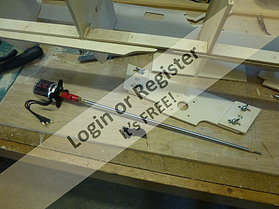
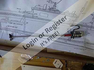
The recommended propshaft is 13" long with an 8mm outer tube and 5mm inner shaft. I purchased this from 'Modelboatbits' along with a nice little oiler clamp system, and a universal coupling with inserts to suit the threaded end of the propshaft and the 5mm plain shaft of the brushless motor.
The recommended prop is a nylon two blade X50, again from Modelboatbits.
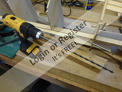
The keel needs to be bored out to receive the propshaft and fortunately I have a 8mm wood bit that is long enough to go through the keel and through bulkhead B4 in one pass. The slot cut in the keel at an earlier stage helps guide the drill bit but still this needs to be done very carefully to maintain correct alignment and angle.
I won't glue the propshaft into position yet, this will be done when the side skins are on and the motor mount and motor can be dry fitted and aligned properly.
[{"id":"1478300309","url":"https:\/\/model-boats.com\/media\/1478300309\/l","thumbUrl":"https:\/\/model-boats.com\/media\/1478300309\/s","name":"1478300309","caption":""},{"id":"1478300333","url":"https:\/\/model-boats.com\/media\/1478300333\/l","thumbUrl":"https:\/\/model-boats.com\/media\/1478300333\/s","name":"1478300333","caption":""},{"id":"1478300362","url":"https:\/\/model-boats.com\/media\/1478300362\/l","thumbUrl":"https:\/\/model-boats.com\/media\/1478300362\/s","name":"1478300362","caption":""},{"id":"1478300402","url":"https:\/\/model-boats.com\/media\/1478300402\/l","thumbUrl":"https:\/\/model-boats.com\/media\/1478300402\/s","name":"1478300402","caption":""}]
The recommended propshaft is 13" long with an 8mm outer tube and 5mm inner shaft. I purchased this from 'Modelboatbits' along with a nice little oiler clamp system, and a universal coupling with inserts to suit the threaded end of the propshaft and the 5mm plain shaft of the brushless motor.
The recommended prop is a nylon two blade X50, again from Modelboatbits.
The keel needs to be bored out to receive the propshaft and fortunately I have a 8mm wood bit that is long enough to go through the keel and through bulkhead B4 in one pass. The slot cut in the keel at an earlier stage helps guide the drill bit but still this needs to be done very carefully to maintain correct alignment and angle.
I won't glue the propshaft into position yet, this will be done when the side skins are on and the motor mount and motor can be dry fitted and aligned properly.

The skinning of the hull is probably the hardest part of the assembly as it involves careful trimming and shaping to ensure a good fit without resorting to fillers for making good. The skins can be bent quite successfully with the application of steam or with a heat gun. I used a combination of the two with the steaming initially relaxing the wood allowing it to be bent to the correct curvatures and the heat gun (electric paint stripper) to 'set' the shape and dry the skins. The bottom skins are fitted first and the edge that meets the keel is trimmed to get a good fit and the edge given a slight chamfer to eliminate a gap where it meets the keel.
I marked the keel with pencil marks at the centre of each bulkhead and marked the skins with a line meeting the chine stringer so that the brass pins in pre drilled holes would drive in easily and not split the bulkhead formers.
Working from bow to stern the skin is pinned to the false rebates on the keel and the bulkhead formers with the application of aliphatic glue, the edge that meets the chine stringers is just clamped into place along its entire length with as many clamps I had to hand.
I used pins temporarily to hold the skin firmly where it lays on the bow chine former and these were removed when the glue set. When the glue has thoroughly set the skins are roughly trimmed where they meet the chine stringers and finished with a plane being careful not to take any material away from the stringer and keeping a good straight edge with no hollows or bumps.
Having repeated the process for the other bottom skin it's the side skins next and they are a bit trickier to do !
[{"id":"1478446807","url":"https:\/\/model-boats.com\/media\/1478446807\/l","thumbUrl":"https:\/\/model-boats.com\/media\/1478446807\/s","name":"1478446807","caption":""},{"id":"1478446830","url":"https:\/\/model-boats.com\/media\/1478446830\/l","thumbUrl":"https:\/\/model-boats.com\/media\/1478446830\/s","name":"1478446830","caption":""},{"id":"1478446881","url":"https:\/\/model-boats.com\/media\/1478446881\/l","thumbUrl":"https:\/\/model-boats.com\/media\/1478446881\/s","name":"1478446881","caption":""},{"id":"1478447294","url":"https:\/\/model-boats.com\/media\/1478447294\/l","thumbUrl":"https:\/\/model-boats.com\/media\/1478447294\/s","name":"1478447294","caption":""}]
The skinning of the hull is probably the hardest part of the assembly as it involves careful trimming and shaping to ensure a good fit without resorting to fillers for making good. The skins can be bent quite successfully with the application of steam or with a heat gun. I used a combination of the two with the steaming initially relaxing the wood allowing it to be bent to the correct curvatures and the heat gun (electric paint stripper) to 'set' the shape and dry the skins. The bottom skins are fitted first and the edge that meets the keel is trimmed to get a good fit and the edge given a slight chamfer to eliminate a gap where it meets the keel.
I marked the keel with pencil marks at the centre of each bulkhead and marked the skins with a line meeting the chine stringer so that the brass pins in pre drilled holes would drive in easily and not split the bulkhead formers.
Working from bow to stern the skin is pinned to the false rebates on the keel and the bulkhead formers with the application of aliphatic glue, the edge that meets the chine stringers is just clamped into place along its entire length with as many clamps I had to hand.
I used pins temporarily to hold the skin firmly where it lays on the bow chine former and these were removed when the glue set. When the glue has thoroughly set the skins are roughly trimmed where they meet the chine stringers and finished with a plane being careful not to take any material away from the stringer and keeping a good straight edge with no hollows or bumps.
Having repeated the process for the other bottom skin it's the side skins next and they are a bit trickier to do !
Hi Mike.
The skins were too large to fit into my steaming tube which is great for the stringers but not the skins. I found the most effective method was to gently heat the skins with my Black & Decker electric paint stripper 'heat gun' in the area where you want to bend.
This causes the glue holding the plys of the skins to relax and you can then bend the skins by hand and as the skin cools it holds the shape of the bend.
There's absolutely no chance that the ply will de-laminate😀
I hope that's helpful.
Rob.
The temporary pins holding the bottom skins on the bow chine former are removed and the bottom skin is very carefully cut back to reveal the upper half of the chine former back to bulkhead B1 as the side skin needs to butt against the bottom skin at this point, the remainder of the side skin overlaps the bottom skin all the way back to the transom.
The side skin is then temporarily clamped in position and carefully measured and marked for trimming to abut the bottom skin on the chine former.
I can't afford to make a mess of this so I measure three times and cut once !.
Once I'm happy with the fit the skin is steamed and formed to the correct curvature. The fixing process is the same as with the bottom skins with pins into the bulkheads and the chine former but clamping only to the gunwhale stringers, no pins were used to fix to the chine stringers, the aliphatic glue provides a very strong bond and the joint will later be strengthened when the chine rubbing strakes are fitted.
[{"id":"1478456942","url":"https:\/\/model-boats.com\/media\/1478456942\/l","thumbUrl":"https:\/\/model-boats.com\/media\/1478456942\/s","name":"1478456942","caption":""},{"id":"1478456978","url":"https:\/\/model-boats.com\/media\/1478456978\/l","thumbUrl":"https:\/\/model-boats.com\/media\/1478456978\/s","name":"1478456978","caption":""},{"id":"1478457032","url":"https:\/\/model-boats.com\/media\/1478457032\/l","thumbUrl":"https:\/\/model-boats.com\/media\/1478457032\/s","name":"1478457032","caption":""},{"id":"1478457058","url":"https:\/\/model-boats.com\/media\/1478457058\/l","thumbUrl":"https:\/\/model-boats.com\/media\/1478457058\/s","name":"1478457058","caption":""}]
The temporary pins holding the bottom skins on the bow chine former are removed and the bottom skin is very carefully cut back to reveal the upper half of the chine former back to bulkhead B1 as the side skin needs to butt against the bottom skin at this point, the remainder of the side skin overlaps the bottom skin all the way back to the transom.
The side skin is then temporarily clamped in position and carefully measured and marked for trimming to abut the bottom skin on the chine former.
I can't afford to make a mess of this so I measure three times and cut once !.
Once I'm happy with the fit the skin is steamed and formed to the correct curvature. The fixing process is the same as with the bottom skins with pins into the bulkheads and the chine former but clamping only to the gunwhale stringers, no pins were used to fix to the chine stringers, the aliphatic glue provides a very strong bond and the joint will later be strengthened when the chine rubbing strakes are fitted.
really nice woodwork skills, I am unable to do that! I just rescue other peoples builds and make them pretty!
If I may, I have some concerns about your drivetrain, something I have spent a lot of time testing etc. That motor, with nimhs just isn't going to deliver the power needed to push this heavy old girl along, please consider lipo's, or even twin screw, you still have time to do this, its very easy, I did it!
As you have seen on the youtube videos, these boats where fast, they handle real great in a straight line, its cornering that things get difficult. One real good tip, make sure the spray rails are square profile. HS93 told me this, and it works a treat to aid turning at speeds, this hull wants to roll quite a lot!
Regarding the mysterious rear light, I saw a picture years ago, it was blue, we thing it had something to do with pre trial river requirements, I cannot find that info anywhere, so left it off mine.
Hi Paul.
Thanks for your encouraging comments.
The motor is a Turnigy SK3-4250-500kv brushless outrunner, batteries are 2 x 9.6v NiMh 5000mA, a combination recommended for this boat by VMW.
You are not the only one to express a concern on it's potential performance but I'll go with what I have and if indeed it does under perform I can easily up-rate the motor and battery combination. The ESC I have is more that capable apparently.
I'm too far down the road to reconfigure to a two motor setup and really I'm building this as a test of my re-awakened model making skills and for the satisfaction of it all rather than terrifying the pond life and myself to boot, assuming I can find a 'pond' that is.
The spray rails are indeed a nice square profile as you suggest and will hopefully help with the cornering.
I'm trying to find out more about the mysterious stern navigation light that appears in a couple 'photos I have seen, I might like to incorporate this in my boat if it's a significant detail...anyone know?
This is the sort of constructive criticism that I was hoping to get from other members to my blog so please do chip in if I'm getting it wrong, albeit too late for me but for others building similar boats.
By the way, my comments about the fire boat content of the plans and docs section is not intended to offend anyone, but I can't understand why 'copyright issues' means that 'photos and drawings have to be deliberately blurred to render them next to useless, it's like giving someone a book to read and then poking then in the eyes!
Rob
The skins have now had plenty of time to set and now need trimming top bottom & stern, the skin is first trimmed with a saw along the chine and then planed flush. Similarly the top of the skin is trimmed and planed flush with the deck all the way round including the transom. I can now shape the keel to the hull profile, fill the nail holes and a tiny bit of filler on the bow and rub it all down to get quite a nice 'pointy'end.
The filler is a two part wood filler from Screwfix that is not as 'hard' as isopon P38 and can be sanded a lot more easily without removing too much of the surrounding area, it's also wood colour !
I'm very pleased with the bow section, particularly as I remember making a bit of a hash of it on my first boat, but then I was only 15 years old.
I need to think about the motor and mount so that I can set the prop shaft in the keel but before that I need to make a supporting cradle for the hull as it's getting a bit big for the bench now.
[{"id":"1478557221","url":"https:\/\/model-boats.com\/media\/1478557221\/l","thumbUrl":"https:\/\/model-boats.com\/media\/1478557221\/s","name":"1478557221","caption":""},{"id":"1478557251","url":"https:\/\/model-boats.com\/media\/1478557251\/l","thumbUrl":"https:\/\/model-boats.com\/media\/1478557251\/s","name":"1478557251","caption":""},{"id":"1478557301","url":"https:\/\/model-boats.com\/media\/1478557301\/l","thumbUrl":"https:\/\/model-boats.com\/media\/1478557301\/s","name":"1478557301","caption":""},{"id":"1478557372","url":"https:\/\/model-boats.com\/media\/1478557372\/l","thumbUrl":"https:\/\/model-boats.com\/media\/1478557372\/s","name":"1478557372","caption":""}]
The skins have now had plenty of time to set and now need trimming top bottom & stern, the skin is first trimmed with a saw along the chine and then planed flush. Similarly the top of the skin is trimmed and planed flush with the deck all the way round including the transom. I can now shape the keel to the hull profile, fill the nail holes and a tiny bit of filler on the bow and rub it all down to get quite a nice 'pointy'end.
The filler is a two part wood filler from Screwfix that is not as 'hard' as isopon P38 and can be sanded a lot more easily without removing too much of the surrounding area, it's also wood colour !
I'm very pleased with the bow section, particularly as I remember making a bit of a hash of it on my first boat, but then I was only 15 years old.
I need to think about the motor and mount so that I can set the prop shaft in the keel but before that I need to make a supporting cradle for the hull as it's getting a bit big for the bench now.
Hi BOATSHED.
Rob here....Edward is quite correct, the Screwfix product number is 51811 and it's on special offer right now.
Use the hardener sparingly, this stuff goes off very rapidly !
Even so it's much better stuff for what we do than isopon car body filler.
Sorry for the late reply, a problem with this site has prevented me and others from logging in but clearly it's all working now (thanks Stephen).
Rob.
Hi both Rob And Ed,
Thanks for your reply. I will be getting some of that by the weekend. The Perkasa hull I bought has had the front was done with balsa blocks and not skinned and has not been done very well. I would have done it with ply right over.
I was going to use P38. But I will no do it your way.
regards
Tom.
As I need to work on the deck and superstructure now I'm going to need something to support the hull securely so it's time to build a stand.
To get the profile of the hull I used a couple of wire coat hangers, the sort you get from the dry cleaners, and carefully bent and formed them to the hull shape at bulkhead B2 and B5, they bend and keep their shape very well and it's easy to transfer the shapes to the 18mm ply end boards. I marked around the outside of the wire to give a clearance gap to allow for the strakes that will be fitted later and some neoprene foam pads to cushion the hull.
The waste wood out with a coping saw and the cut edges filed and sanded smooth.
Both end boards were then clamped together and drilled with a suitable wood bit to take the four large diameter dowels which were glued and pinned, all the while ensuring that the entire assembly was as square and true as possible.
The end result is a very rigid and stable stand that will protect the hull, keel and rudder etc.
I won't bother painting and finishing this properly until the construction work is finished.
[{"id":"1478800871","url":"https:\/\/model-boats.com\/media\/1478800871\/l","thumbUrl":"https:\/\/model-boats.com\/media\/1478800871\/s","name":"1478800871","caption":""},{"id":"1478800895","url":"https:\/\/model-boats.com\/media\/1478800895\/l","thumbUrl":"https:\/\/model-boats.com\/media\/1478800895\/s","name":"1478800895","caption":""},{"id":"1478800945","url":"https:\/\/model-boats.com\/media\/1478800945\/l","thumbUrl":"https:\/\/model-boats.com\/media\/1478800945\/s","name":"1478800945","caption":""},{"id":"1478801020","url":"https:\/\/model-boats.com\/media\/1478801020\/l","thumbUrl":"https:\/\/model-boats.com\/media\/1478801020\/s","name":"1478801020","caption":""}]
As I need to work on the deck and superstructure now I'm going to need something to support the hull securely so it's time to build a stand.
To get the profile of the hull I used a couple of wire coat hangers, the sort you get from the dry cleaners, and carefully bent and formed them to the hull shape at bulkhead B2 and B5, they bend and keep their shape very well and it's easy to transfer the shapes to the 18mm ply end boards. I marked around the outside of the wire to give a clearance gap to allow for the strakes that will be fitted later and some neoprene foam pads to cushion the hull.
The waste wood out with a coping saw and the cut edges filed and sanded smooth.
Both end boards were then clamped together and drilled with a suitable wood bit to take the four large diameter dowels which were glued and pinned, all the while ensuring that the entire assembly was as square and true as possible.
The end result is a very rigid and stable stand that will protect the hull, keel and rudder etc.
I won't bother painting and finishing this properly until the construction work is finished.
Now that the side skins are fitted it's possible to get the motor mount in position so that the prop shaft can be set into the keel properly.
The kit includes a very clever mounting system for the motor that once fixed in place will still allow for minor adjustment to get the prop shaft lined up as straight and true as possible.
The motor mount is carefully marked and drilled to accept the motors mounting plate and is then bolted in place with cap head bolts and self-locking nuts, the mounting cheeks are the bolted to the mount with wing nuts and spring washers which will provide the motor adjustment.
All of the mounting hardware I have used is stainless steel and is not included in the VMW kit so these were sourced from eBay suppliers.
I also found on eBay a 5mm to 5mm rigid coupling and used this temporarily in place of the flexible coupling to hold the motor, coupling and shaft in perfect alignment while the motor mount is glued and pinned to the hull side skins.
Once I was happy with the alignment I could epoxy the prop shaft into the keel, the rigid coupling can then be replaced with the flexible coupling.
Spinning the outrunner motor case with the shaft attached proved very smooth without any tight spots or noise, at this stage the shaft is un-lubricated and I will be fitting an oiler sytem for this.
I also fixed a brass angle plate between the bottom of the motor mount and the keel to further locate and support the motor mount. it should also (hopefully) prevent any twisting or deflection when the motor is under load and reduce any vibration.
[{"id":"1478804777","url":"https:\/\/model-boats.com\/media\/1478804777\/l","thumbUrl":"https:\/\/model-boats.com\/media\/1478804777\/s","name":"1478804777","caption":""},{"id":"1478804825","url":"https:\/\/model-boats.com\/media\/1478804825\/l","thumbUrl":"https:\/\/model-boats.com\/media\/1478804825\/s","name":"1478804825","caption":""},{"id":"1478804858","url":"https:\/\/model-boats.com\/media\/1478804858\/l","thumbUrl":"https:\/\/model-boats.com\/media\/1478804858\/s","name":"1478804858","caption":""},{"id":"1478804886","url":"https:\/\/model-boats.com\/media\/1478804886\/l","thumbUrl":"https:\/\/model-boats.com\/media\/1478804886\/s","name":"1478804886","caption":""}]
Now that the side skins are fitted it's possible to get the motor mount in position so that the prop shaft can be set into the keel properly.
The kit includes a very clever mounting system for the motor that once fixed in place will still allow for minor adjustment to get the prop shaft lined up as straight and true as possible.
The motor mount is carefully marked and drilled to accept the motors mounting plate and is then bolted in place with cap head bolts and self-locking nuts, the mounting cheeks are the bolted to the mount with wing nuts and spring washers which will provide the motor adjustment.
All of the mounting hardware I have used is stainless steel and is not included in the VMW kit so these were sourced from eBay suppliers.
I also found on eBay a 5mm to 5mm rigid coupling and used this temporarily in place of the flexible coupling to hold the motor, coupling and shaft in perfect alignment while the motor mount is glued and pinned to the hull side skins.
Once I was happy with the alignment I could epoxy the prop shaft into the keel, the rigid coupling can then be replaced with the flexible coupling.
Spinning the outrunner motor case with the shaft attached proved very smooth without any tight spots or noise, at this stage the shaft is un-lubricated and I will be fitting an oiler sytem for this.
I also fixed a brass angle plate between the bottom of the motor mount and the keel to further locate and support the motor mount. it should also (hopefully) prevent any twisting or deflection when the motor is under load and reduce any vibration.
So the instructions say "make up a brass skeg from 22swg brass strip", OK so how difficult is that !
Bought some 22swg brass, cut some strips, formed one strip around an 8mm drill bit to make a tube, cut another strip and soft soldered it all together.
It looked rubbish and had no strength at all. 😭
Time to think again...hmmm.......need some expert help here.
[{"id":"1478888683","url":"https:\/\/model-boats.com\/media\/1478888683\/l","thumbUrl":"https:\/\/model-boats.com\/media\/1478888683\/s","name":"1478888683","caption":""},{"id":"1478888731","url":"https:\/\/model-boats.com\/media\/1478888731\/l","thumbUrl":"https:\/\/model-boats.com\/media\/1478888731\/s","name":"1478888731","caption":""},{"id":"1478888775","url":"https:\/\/model-boats.com\/media\/1478888775\/l","thumbUrl":"https:\/\/model-boats.com\/media\/1478888775\/s","name":"1478888775","caption":""}]
So the instructions say "make up a brass skeg from 22swg brass strip", OK so how difficult is that !
Bought some 22swg brass, cut some strips, formed one strip around an 8mm drill bit to make a tube, cut another strip and soft soldered it all together.
It looked rubbish and had no strength at all. 😭
Time to think again...hmmm.......need some expert help here.
So I called my younger brother, who has........ a lathe !
'No problem' he said, 'send me a drawing of the bit you need turned and I'll post it to you'.
A short while later it arrived in the post, it fits the shaft like a glove and looks the part too.
I carefully cut and filed a flat bottomed groove along it's length and with some new 14swg brass strip and a 'silver soldering kit' I set about putting it together.
Despite my rather heavy silver soldering, (never done that before) it cleaned up very nicely and the solder joint is strong and firm, but best of all it actually looks worthy of fitting to my boat 😊
The skeg was fitted at the same time as the prop shaft, set into a slot cut through the keel and epoxied firmly in place.
[{"id":"1478889391","url":"https:\/\/model-boats.com\/media\/1478889391\/l","thumbUrl":"https:\/\/model-boats.com\/media\/1478889391\/s","name":"1478889391","caption":""},{"id":"1478889422","url":"https:\/\/model-boats.com\/media\/1478889422\/l","thumbUrl":"https:\/\/model-boats.com\/media\/1478889422\/s","name":"1478889422","caption":""},{"id":"1478889456","url":"https:\/\/model-boats.com\/media\/1478889456\/l","thumbUrl":"https:\/\/model-boats.com\/media\/1478889456\/s","name":"1478889456","caption":""},{"id":"1478889494","url":"https:\/\/model-boats.com\/media\/1478889494\/l","thumbUrl":"https:\/\/model-boats.com\/media\/1478889494\/s","name":"1478889494","caption":""}]
So I called my younger brother, who has........ a lathe !
'No problem' he said, 'send me a drawing of the bit you need turned and I'll post it to you'.
A short while later it arrived in the post, it fits the shaft like a glove and looks the part too.
I carefully cut and filed a flat bottomed groove along it's length and with some new 14swg brass strip and a 'silver soldering kit' I set about putting it together.
Despite my rather heavy silver soldering, (never done that before) it cleaned up very nicely and the solder joint is strong and firm, but best of all it actually looks worthy of fitting to my boat 😊
The skeg was fitted at the same time as the prop shaft, set into a slot cut through the keel and epoxied firmly in place.
Here are some pictures of the skeg fitting, and the position of the oiler system on the propshaft.
The latter is supplied with a short silicone tube with a stopper and also a syringe for applying the lubricant, grease or oil?...a controversial subject it seems, so I have yet to decide ❓ .
I wrapped a single turn of gas PTFE tape (slightly thicker than ordinary plumbing PTFE) around the tube before clamping it into place and drilling through into the shaft tube. This should ensure an oil tight seal. it's very important that any swarf that ends up inside the shaft is flushed out as it could damage the bearing within the prop tube. I have added a ply reinforcing plates on either side of the bulkhead for good measure.
The ply strips either side of the keel will form part of the battery supports in that compartment.
[{"id":"1478965391","url":"https:\/\/model-boats.com\/media\/1478965391\/l","thumbUrl":"https:\/\/model-boats.com\/media\/1478965391\/s","name":"1478965391","caption":""},{"id":"1478965434","url":"https:\/\/model-boats.com\/media\/1478965434\/l","thumbUrl":"https:\/\/model-boats.com\/media\/1478965434\/s","name":"1478965434","caption":""},{"id":"1478965473","url":"https:\/\/model-boats.com\/media\/1478965473\/l","thumbUrl":"https:\/\/model-boats.com\/media\/1478965473\/s","name":"1478965473","caption":""},{"id":"1478965507","url":"https:\/\/model-boats.com\/media\/1478965507\/l","thumbUrl":"https:\/\/model-boats.com\/media\/1478965507\/s","name":"1478965507","caption":""}]
Here are some pictures of the skeg fitting, and the position of the oiler system on the propshaft.
The latter is supplied with a short silicone tube with a stopper and also a syringe for applying the lubricant, grease or oil?...a controversial subject it seems, so I have yet to decide ❓ .
I wrapped a single turn of gas PTFE tape (slightly thicker than ordinary plumbing PTFE) around the tube before clamping it into place and drilling through into the shaft tube. This should ensure an oil tight seal. it's very important that any swarf that ends up inside the shaft is flushed out as it could damage the bearing within the prop tube. I have added a ply reinforcing plates on either side of the bulkhead for good measure.
The ply strips either side of the keel will form part of the battery supports in that compartment.
I'm not very happy with the quality of the plastic water scoop that I have purchased, the threaded portion is only just sufficient to pass through the keel and frankly it looks a bit naff.
Equally, the water outlet I have as similarly poor and I can't seem to find a brass equivalent anywhere, so I decided to make my own.
The tube is 6mm brass and needs to be bent and flared as a scoop so to do the bending I made a jig with a fixed circular former that I filed a round groove in around it's circumference and a square block to retain the tube.
The tube was then annealed to soften it and bent around the former, I also put a curtain wire inside the tube to prevent the tube crushing and although it helped the tube did distort slightly.
Perhaps I should have tried the 'dry salt' or 'fine sand' method but overall I am pleased with end result.
Once in place in the hole I drilled through the keel it looks like it will do the job but it definitely needs a flange of sorts to make it look better.
Maybe a bit of turned brass ?...... 💭
[{"id":"1478967604","url":"https:\/\/model-boats.com\/media\/1478967604\/l","thumbUrl":"https:\/\/model-boats.com\/media\/1478967604\/s","name":"1478967604","caption":""},{"id":"1478967638","url":"https:\/\/model-boats.com\/media\/1478967638\/l","thumbUrl":"https:\/\/model-boats.com\/media\/1478967638\/s","name":"1478967638","caption":""},{"id":"1478967695","url":"https:\/\/model-boats.com\/media\/1478967695\/l","thumbUrl":"https:\/\/model-boats.com\/media\/1478967695\/s","name":"1478967695","caption":""},{"id":"1478967729","url":"https:\/\/model-boats.com\/media\/1478967729\/l","thumbUrl":"https:\/\/model-boats.com\/media\/1478967729\/s","name":"1478967729","caption":""}]
I'm not very happy with the quality of the plastic water scoop that I have purchased, the threaded portion is only just sufficient to pass through the keel and frankly it looks a bit naff.
Equally, the water outlet I have as similarly poor and I can't seem to find a brass equivalent anywhere, so I decided to make my own.
The tube is 6mm brass and needs to be bent and flared as a scoop so to do the bending I made a jig with a fixed circular former that I filed a round groove in around it's circumference and a square block to retain the tube.
The tube was then annealed to soften it and bent around the former, I also put a curtain wire inside the tube to prevent the tube crushing and although it helped the tube did distort slightly.
Perhaps I should have tried the 'dry salt' or 'fine sand' method but overall I am pleased with end result.
Once in place in the hole I drilled through the keel it looks like it will do the job but it definitely needs a flange of sorts to make it look better.
Maybe a bit of turned brass ?...... 💭
"Hi bro......any chance you could ?....great, I'll come and visit and watch the master at work"
Clever bugger, and so modest too ! 😁
[{"id":"1478971547","url":"https:\/\/model-boats.com\/media\/1478971547\/l","thumbUrl":"https:\/\/model-boats.com\/media\/1478971547\/s","name":"1478971547","caption":""},{"id":"1478971577","url":"https:\/\/model-boats.com\/media\/1478971577\/l","thumbUrl":"https:\/\/model-boats.com\/media\/1478971577\/s","name":"1478971577","caption":""},{"id":"1478971628","url":"https:\/\/model-boats.com\/media\/1478971628\/l","thumbUrl":"https:\/\/model-boats.com\/media\/1478971628\/s","name":"1478971628","caption":""},{"id":"1478971689","url":"https:\/\/model-boats.com\/media\/1478971689\/l","thumbUrl":"https:\/\/model-boats.com\/media\/1478971689\/s","name":"1478971689","caption":""}]
The next stage is to fit the deck skins but before doing so I drilled some holes in the bulkheads to pass the wiring for the lighting circuits and servos through later.
The battery supports are in place and I have cut two larger holes in bulkheads B4 & B5 and bridged them with a bar to act as a support for wiring and water cooling tubes so everything is supported and looks tidy. I then applied 3 coats of sanding sealer to all accessible areas inside the hull, rubbing down between each coat. I forgot to mention previously that before fitting the bottom and side skins the voids at the bow ahead of B1 were sealed with sanding sealer. I used silver Hammerite paint over the sanding sealer as suggested in the building instructions, and when dried and hardened has provided an attractive and durable finish.
The insides of the cabin sides and cabin formers will probably be painted black at a later stage.
[{"id":"1479153222","url":"https:\/\/model-boats.com\/media\/1479153222\/l","thumbUrl":"https:\/\/model-boats.com\/media\/1479153222\/s","name":"1479153222","caption":""},{"id":"1479153250","url":"https:\/\/model-boats.com\/media\/1479153250\/l","thumbUrl":"https:\/\/model-boats.com\/media\/1479153250\/s","name":"1479153250","caption":""},{"id":"1479153352","url":"https:\/\/model-boats.com\/media\/1479153352\/l","thumbUrl":"https:\/\/model-boats.com\/media\/1479153352\/s","name":"1479153352","caption":""},{"id":"1479153455","url":"https:\/\/model-boats.com\/media\/1479153455\/l","thumbUrl":"https:\/\/model-boats.com\/media\/1479153455\/s","name":"1479153455","caption":""}]
The next stage is to fit the deck skins but before doing so I drilled some holes in the bulkheads to pass the wiring for the lighting circuits and servos through later.
The battery supports are in place and I have cut two larger holes in bulkheads B4 & B5 and bridged them with a bar to act as a support for wiring and water cooling tubes so everything is supported and looks tidy. I then applied 3 coats of sanding sealer to all accessible areas inside the hull, rubbing down between each coat. I forgot to mention previously that before fitting the bottom and side skins the voids at the bow ahead of B1 were sealed with sanding sealer. I used silver Hammerite paint over the sanding sealer as suggested in the building instructions, and when dried and hardened has provided an attractive and durable finish.
The insides of the cabin sides and cabin formers will probably be painted black at a later stage.
The deck support fillet supplied in the kit is a bit too narrow to support the foredeck skins when they are butted together so I made a substitute from some obechi strip laminated together resulting in a larger surface area for the skins to be glued and pinned to.
I fitted the deck skins in a different order to the instructions starting with the side decks, but made sure that the joins butt together over the bulkheads. All are glued with aliphatic and pinned in place, clamps were used to hold the deck skins down where they meet the cabin sides as I didn't want to use pins there. The towing hook deck and transom decks are also fitted.
Finally all the deck skins are trimmed flush with the hull sides, the pins punched just below the surface and a little filler applied and rubbed down.
[{"id":"1479418765","url":"https:\/\/model-boats.com\/media\/1479418765\/l","thumbUrl":"https:\/\/model-boats.com\/media\/1479418765\/s","name":"1479418765","caption":""},{"id":"1479418797","url":"https:\/\/model-boats.com\/media\/1479418797\/l","thumbUrl":"https:\/\/model-boats.com\/media\/1479418797\/s","name":"1479418797","caption":""},{"id":"1479418869","url":"https:\/\/model-boats.com\/media\/1479418869\/l","thumbUrl":"https:\/\/model-boats.com\/media\/1479418869\/s","name":"1479418869","caption":""},{"id":"1479418957","url":"https:\/\/model-boats.com\/media\/1479418957\/l","thumbUrl":"https:\/\/model-boats.com\/media\/1479418957\/s","name":"1479418957","caption":""}]
The deck support fillet supplied in the kit is a bit too narrow to support the foredeck skins when they are butted together so I made a substitute from some obechi strip laminated together resulting in a larger surface area for the skins to be glued and pinned to.
I fitted the deck skins in a different order to the instructions starting with the side decks, but made sure that the joins butt together over the bulkheads. All are glued with aliphatic and pinned in place, clamps were used to hold the deck skins down where they meet the cabin sides as I didn't want to use pins there. The towing hook deck and transom decks are also fitted.
Finally all the deck skins are trimmed flush with the hull sides, the pins punched just below the surface and a little filler applied and rubbed down.
You might not want to do this, but a little tip I was given, stand it on its nose and pour some resin into the bow, particularly at deck, it just firm everything up, and provides a good strong seal against those "too fast into the bank" moments
The original aerokits versions suffered from delamination as in picture one above, which rotted the top deck. I have seen quite a few do this over time, the resin trick seems to stop it, just a thought"!
Hi Paul.
That's a good tip, particularly if you are renovating an old boat.
I'm using 100gsm fibreglass twill on the outside of the hull with three coats of resin, I'm hoping that will be sufficient reinforcement. The same supplier does carbon fibre and Kevlar cloth, both very costly, and that would make the hull almost bullet proof !
I have no doubt that at some time I will inflict some 'pond rash' on my hull but that's all part of the deal I suppose 😫 .
Rob.
Whilst researching finishing techniques for the hull I sent off for some samples of woven fibreglass material so that I could choose an appropriate gsm weight. I settled on a 100gsm woven glassfibre twill cloth that is particularly good at conforming to compound curves. The same supplier also does carbon fibre and Kevlar cloth and they are prohibitively expensive but a narrow strip could be good to further protect the bow and keel I suppose.
The resin I have chosen has a 'pot life' of 95 minutes so work can be done at a reasonable pace, the alternative is a 'fast' hardener that has a 17 minute pot life which might entail rather frantic application!
I ordered 3 metres of 1m wide cloth, a 1kg pack of resin & 'slow' hardener, some mixing cups and sticks and 10 disposable brushes for £45 including shipping.
When it all arrived I thought it would be good to do a test piece before the real thing.
The resin and hardener are mixed in a 100:30 ratio by weight, hence the electronic scales in the picture.
I found that the easiest way to use this stuff was to apply a thin coat of resin to the surface, lay the cloth onto it and gently stipple the cloth into the resin, a further thin coat is then brushed on then set aside to cure.
I found it best not to overwork the resin into the cloth, it's definitely a case of 'less is more' as you can easily ripple the cloth and having done so it can be made worse by trying to flatten it. No need for plastic cards or such to smooth it out, it self-levels nicely.
I left it to cure for a couple of days and then experimented with sanding, a detail sander with an 120 grit pad achieved a very good flat surface without going through the cloth.
Two further coats of resin with a rub down between, each with finer grade abrasives, resulted in a glass smooth surface that when keyed would be an ideal surface for the paint system.
Encouraged by these results I decided to do the thing for real 😰
The supplier for these materials is www.easycomposites.co.uk if anyone is interested.
[{"id":"1479489477","url":"https:\/\/model-boats.com\/media\/1479489477\/l","thumbUrl":"https:\/\/model-boats.com\/media\/1479489477\/s","name":"1479489477","caption":""},{"id":"1479489511","url":"https:\/\/model-boats.com\/media\/1479489511\/l","thumbUrl":"https:\/\/model-boats.com\/media\/1479489511\/s","name":"1479489511","caption":""},{"id":"1479489558","url":"https:\/\/model-boats.com\/media\/1479489558\/l","thumbUrl":"https:\/\/model-boats.com\/media\/1479489558\/s","name":"1479489558","caption":""},{"id":"1479489604","url":"https:\/\/model-boats.com\/media\/1479489604\/l","thumbUrl":"https:\/\/model-boats.com\/media\/1479489604\/s","name":"1479489604","caption":""}]
Whilst researching finishing techniques for the hull I sent off for some samples of woven fibreglass material so that I could choose an appropriate gsm weight. I settled on a 100gsm woven glassfibre twill cloth that is particularly good at conforming to compound curves. The same supplier also does carbon fibre and Kevlar cloth and they are prohibitively expensive but a narrow strip could be good to further protect the bow and keel I suppose.
The resin I have chosen has a 'pot life' of 95 minutes so work can be done at a reasonable pace, the alternative is a 'fast' hardener that has a 17 minute pot life which might entail rather frantic application!
I ordered 3 metres of 1m wide cloth, a 1kg pack of resin & 'slow' hardener, some mixing cups and sticks and 10 disposable brushes for £45 including shipping.
When it all arrived I thought it would be good to do a test piece before the real thing.
The resin and hardener are mixed in a 100:30 ratio by weight, hence the electronic scales in the picture.
I found that the easiest way to use this stuff was to apply a thin coat of resin to the surface, lay the cloth onto it and gently stipple the cloth into the resin, a further thin coat is then brushed on then set aside to cure.
I found it best not to overwork the resin into the cloth, it's definitely a case of 'less is more' as you can easily ripple the cloth and having done so it can be made worse by trying to flatten it. No need for plastic cards or such to smooth it out, it self-levels nicely.
I left it to cure for a couple of days and then experimented with sanding, a detail sander with an 120 grit pad achieved a very good flat surface without going through the cloth.
Two further coats of resin with a rub down between, each with finer grade abrasives, resulted in a glass smooth surface that when keyed would be an ideal surface for the paint system.
Encouraged by these results I decided to do the thing for real 😰
The supplier for these materials is www.easycomposites.co.uk if anyone is interested.
Easy Composites do some "how to" videos on there web site, i have used their lighter grade glass cloth and got superb results. i do agree that the longer curing resin is better, you dont need to rush with the longer time to adjust and apply.
The hull was prepared for fibreglassing, any pins are punched below the surface, filled and rubbed down with a fine grit paper. The wood does not need any sanding sealer applied as this will react with the epoxy resin.
I cut the cloth roughly to size and shape and laid onto the bottom skin, the upper edge was lightly taped with masking tape to hold it in place.
The resin is mixed to the correct 100:30 ratio and stirred well, the pot life is 95 minutes and will allow me to take my time to get this right.
My previous test was very helpful in establishing a working sequence and I know how the materials will react when I start working them and how much time I have before the brush stops brushing and starts dragging the resin.
The cloth is folded over to the other side of the keel and a thin coat of resin applied over the skin and the side of the keel and then the fabric is carefully folded back onto the wet resin.
The resin immediately starts to draw the cloth to the surface and a very light brushing from the centre outwards helps to make it smooth and flat, the remaining resin can then be gently brushed onto the cloth so that there is an even coating. The cloth needed to be pushed up against the keel sides and I used a steel rule edge to get it into the junction of hull and keel.
I decided to trim the cloth just at the bow along the line of the join in the skins whilst the rein was still wet so that I would have a clean butt join in the cloth in this region instead of an overlap, probably not really necessary as an overlap should sand down ok and that join will be covered by the chine stringer, but it seemed like a good idea anyway.
I did a similar thing on the keel below the propshaft and around the skeg.
This was done with a sharp new Stanley knife blade without disturbing the cloth and the excess cloth removed.
Once the cloth is on you must resist the urge to brush on any more resin or smooth it out any more, this first resin coating only needs to be light as subsequent coats will build up and fill the cloth weave.
I let it to cure overnight and the following day is still felt tacky so I erred on the side of caution and left it for a further day until it was entirely dry to the touch.
The excess cloth was then trimmed back with a sharp blade. Caution, be careful because the cut edge of the cloth is itself very sharp, as I found out the hard way!
Feeling quite satisfied with these initial results and a great deal more confident I repeated the process for the other bottom skin.
At this rate of progress, allowing for proper curing of the resin, it will take 8 days just to cover all five faces of the hull with cloth alone, but a wise man said 'a job worth doing is a job worth doing well' 😄
[{"id":"1479572558","url":"https:\/\/model-boats.com\/media\/1479572558\/l","thumbUrl":"https:\/\/model-boats.com\/media\/1479572558\/s","name":"1479572558","caption":""},{"id":"1479572613","url":"https:\/\/model-boats.com\/media\/1479572613\/l","thumbUrl":"https:\/\/model-boats.com\/media\/1479572613\/s","name":"1479572613","caption":""},{"id":"1479572675","url":"https:\/\/model-boats.com\/media\/1479572675\/l","thumbUrl":"https:\/\/model-boats.com\/media\/1479572675\/s","name":"1479572675","caption":""},{"id":"1479572727","url":"https:\/\/model-boats.com\/media\/1479572727\/l","thumbUrl":"https:\/\/model-boats.com\/media\/1479572727\/s","name":"1479572727","caption":""}]
The hull was prepared for fibreglassing, any pins are punched below the surface, filled and rubbed down with a fine grit paper. The wood does not need any sanding sealer applied as this will react with the epoxy resin.
I cut the cloth roughly to size and shape and laid onto the bottom skin, the upper edge was lightly taped with masking tape to hold it in place.
The resin is mixed to the correct 100:30 ratio and stirred well, the pot life is 95 minutes and will allow me to take my time to get this right.
My previous test was very helpful in establishing a working sequence and I know how the materials will react when I start working them and how much time I have before the brush stops brushing and starts dragging the resin.
The cloth is folded over to the other side of the keel and a thin coat of resin applied over the skin and the side of the keel and then the fabric is carefully folded back onto the wet resin.
The resin immediately starts to draw the cloth to the surface and a very light brushing from the centre outwards helps to make it smooth and flat, the remaining resin can then be gently brushed onto the cloth so that there is an even coating. The cloth needed to be pushed up against the keel sides and I used a steel rule edge to get it into the junction of hull and keel.
I decided to trim the cloth just at the bow along the line of the join in the skins whilst the rein was still wet so that I would have a clean butt join in the cloth in this region instead of an overlap, probably not really necessary as an overlap should sand down ok and that join will be covered by the chine stringer, but it seemed like a good idea anyway.
I did a similar thing on the keel below the propshaft and around the skeg.
This was done with a sharp new Stanley knife blade without disturbing the cloth and the excess cloth removed.
Once the cloth is on you must resist the urge to brush on any more resin or smooth it out any more, this first resin coating only needs to be light as subsequent coats will build up and fill the cloth weave.
I let it to cure overnight and the following day is still felt tacky so I erred on the side of caution and left it for a further day until it was entirely dry to the touch.
The excess cloth was then trimmed back with a sharp blade. Caution, be careful because the cut edge of the cloth is itself very sharp, as I found out the hard way!
Feeling quite satisfied with these initial results and a great deal more confident I repeated the process for the other bottom skin.
At this rate of progress, allowing for proper curing of the resin, it will take 8 days just to cover all five faces of the hull with cloth alone, but a wise man said 'a job worth doing is a job worth doing well' 😄
The fibreglassing process is turning out to be a great deal easier than I anticipated, the cloth weave allows it to conform to the hull shape without any creasing, and the resin brushes on very easily and has no unpleasant smell at all.
I had read other build blogs where the resin was described as having an unpleasant smell and was difficult to work with, perhaps that's because this is epoxy rather than polyester?
In retrospect I could have ordered an alternative resin kit from the supplier where two bottles of hardener are supplied, one slow (95 min pot life) and one fast (17min pot life), because as my confidence increased I could probably do an application with the fast hardener in the shorter time and thus curing time would also be correspondingly quicker.
The transom is the last face to do and once that had cured I could then give the complete hull it's first rub down before I shape and fix the gunwhale and the chine rubbing strakes.
Once these are on I can apply the two further resin coats to get the final finish.
[{"id":"1479664573","url":"https:\/\/model-boats.com\/media\/1479664573\/l","thumbUrl":"https:\/\/model-boats.com\/media\/1479664573\/s","name":"1479664573","caption":""},{"id":"1479664624","url":"https:\/\/model-boats.com\/media\/1479664624\/l","thumbUrl":"https:\/\/model-boats.com\/media\/1479664624\/s","name":"1479664624","caption":""},{"id":"1479664654","url":"https:\/\/model-boats.com\/media\/1479664654\/l","thumbUrl":"https:\/\/model-boats.com\/media\/1479664654\/s","name":"1479664654","caption":""},{"id":"1479664683","url":"https:\/\/model-boats.com\/media\/1479664683\/l","thumbUrl":"https:\/\/model-boats.com\/media\/1479664683\/s","name":"1479664683","caption":""}]
The fibreglassing process is turning out to be a great deal easier than I anticipated, the cloth weave allows it to conform to the hull shape without any creasing, and the resin brushes on very easily and has no unpleasant smell at all.
I had read other build blogs where the resin was described as having an unpleasant smell and was difficult to work with, perhaps that's because this is epoxy rather than polyester?
In retrospect I could have ordered an alternative resin kit from the supplier where two bottles of hardener are supplied, one slow (95 min pot life) and one fast (17min pot life), because as my confidence increased I could probably do an application with the fast hardener in the shorter time and thus curing time would also be correspondingly quicker.
The transom is the last face to do and once that had cured I could then give the complete hull it's first rub down before I shape and fix the gunwhale and the chine rubbing strakes.
Once these are on I can apply the two further resin coats to get the final finish.
Thanks all for your kind responses, it's a shame I can only post 4 pics at a time as I would like to show more detail.
I'll try to keep it all interesting and if you think they are worthy please 'like' the postings.
Robbob.
Because the fibreglassing process takes a while, there's time to consider other things that need to be done such as the wheelhouse, cabin roofs and hatches, and the electrics.
The electrics are very straightforward and my initial drawings are transformed into a panel that also contains the master power switch, fuse holder and a charging socket.
All the wiring is in 12awg silicone insulated wire and all connections are soldered and insulated with heat shrink.
Initially I used large Futaba connectors but having assembled and tested the loom I'm not very confident of the current handling of these so I replaced them all with XT60 connector that are rated at 65A.
I'll leave the Futaba charging connector in the switch panel as this doesn't need to be uprated.
The master switch is a high current DPDT, centre off type that in one position connect the battery supply to the ESC and motor via the fuse and in the other position to the charging socket.
Although the ESC has a BEC I will supply the receiver and lighting circuits from separate battery supplies, mustn't forget to remove the power wire from the ESC servo connector!
I have incorporated an in-line ammeter in the loom that should monitor and log peak amps and volts, it's only rated at 30A and I'm not sure that it's up to the job, if not I know that 'Component-shop' do something similar that will meter up to 150A for about £18 or so.
I have chosen a Turnigy charger from Hobbyking that will accommodate the 16 cell NiMh (19.2v) series battery system so that the charging can be done with the batteries in situ, the charger has a 12v DC input so this can done at the lakeside from a car battery if required, but it has no AC input. it will also handle LiPO batteries if I decide to switch chemistry !.
That means that I'll need a meaty DC power supply to run the charger on the bench and I have just the thing for the job.....
[{"id":"1479752440","url":"https:\/\/model-boats.com\/media\/1479752440\/l","thumbUrl":"https:\/\/model-boats.com\/media\/1479752440\/s","name":"1479752440","caption":""},{"id":"1479752480","url":"https:\/\/model-boats.com\/media\/1479752480\/l","thumbUrl":"https:\/\/model-boats.com\/media\/1479752480\/s","name":"1479752480","caption":""},{"id":"1479752522","url":"https:\/\/model-boats.com\/media\/1479752522\/l","thumbUrl":"https:\/\/model-boats.com\/media\/1479752522\/s","name":"1479752522","caption":""},{"id":"1479752712","url":"https:\/\/model-boats.com\/media\/1479752712\/l","thumbUrl":"https:\/\/model-boats.com\/media\/1479752712\/s","name":"1479752712","caption":""}]
Because the fibreglassing process takes a while, there's time to consider other things that need to be done such as the wheelhouse, cabin roofs and hatches, and the electrics.
The electrics are very straightforward and my initial drawings are transformed into a panel that also contains the master power switch, fuse holder and a charging socket.
All the wiring is in 12awg silicone insulated wire and all connections are soldered and insulated with heat shrink.
Initially I used large Futaba connectors but having assembled and tested the loom I'm not very confident of the current handling of these so I replaced them all with XT60 connector that are rated at 65A.
I'll leave the Futaba charging connector in the switch panel as this doesn't need to be uprated.
The master switch is a high current DPDT, centre off type that in one position connect the battery supply to the ESC and motor via the fuse and in the other position to the charging socket.
Although the ESC has a BEC I will supply the receiver and lighting circuits from separate battery supplies, mustn't forget to remove the power wire from the ESC servo connector!
I have incorporated an in-line ammeter in the loom that should monitor and log peak amps and volts, it's only rated at 30A and I'm not sure that it's up to the job, if not I know that 'Component-shop' do something similar that will meter up to 150A for about £18 or so.
I have chosen a Turnigy charger from Hobbyking that will accommodate the 16 cell NiMh (19.2v) series battery system so that the charging can be done with the batteries in situ, the charger has a 12v DC input so this can done at the lakeside from a car battery if required, but it has no AC input. it will also handle LiPO batteries if I decide to switch chemistry !.
That means that I'll need a meaty DC power supply to run the charger on the bench and I have just the thing for the job.....
The power supply that I want to go with the Turnigy charger is out of stock at Hobbyking so as a temporary measure I have decided to convert an old PC power supply for the purpose.
I'm not going into any detail on how this is achieved because unless you have the required skills and knowledge it is best not to mess with power supplies. 💀
A PC power supply actually has a number of different voltage outputs but I'll just be utilising the 12v output.
Two insulated sockets are fitted to the side of the power supply case for the output, and a switch and a couple of led's and current limiting resistors are fitted to the back panel, the existing rocker switch is the main on/off switch and the small toggle switch 'starts' the power supply, the LED's just indicate power on and 12v output present.
For now this unit will be sufficient for my purposes until the unit I want is back in stock at Hobbyking, in the meantime I am now able to charge the NiMH battery packs that have arrived and test the boats electrical system.
[{"id":"1479761429","url":"https:\/\/model-boats.com\/media\/1479761429\/l","thumbUrl":"https:\/\/model-boats.com\/media\/1479761429\/s","name":"1479761429","caption":""},{"id":"1479761463","url":"https:\/\/model-boats.com\/media\/1479761463\/l","thumbUrl":"https:\/\/model-boats.com\/media\/1479761463\/s","name":"1479761463","caption":""},{"id":"1479761515","url":"https:\/\/model-boats.com\/media\/1479761515\/l","thumbUrl":"https:\/\/model-boats.com\/media\/1479761515\/s","name":"1479761515","caption":""},{"id":"1479761566","url":"https:\/\/model-boats.com\/media\/1479761566\/l","thumbUrl":"https:\/\/model-boats.com\/media\/1479761566\/s","name":"1479761566","caption":""}]
The power supply that I want to go with the Turnigy charger is out of stock at Hobbyking so as a temporary measure I have decided to convert an old PC power supply for the purpose.
I'm not going into any detail on how this is achieved because unless you have the required skills and knowledge it is best not to mess with power supplies. 💀
A PC power supply actually has a number of different voltage outputs but I'll just be utilising the 12v output.
Two insulated sockets are fitted to the side of the power supply case for the output, and a switch and a couple of led's and current limiting resistors are fitted to the back panel, the existing rocker switch is the main on/off switch and the small toggle switch 'starts' the power supply, the LED's just indicate power on and 12v output present.
For now this unit will be sufficient for my purposes until the unit I want is back in stock at Hobbyking, in the meantime I am now able to charge the NiMH battery packs that have arrived and test the boats electrical system.
Just wanted to thank you for posting all the valuable information on your build. I'm just getting back into the hobby after too many years away and appreciate the construction details that you include. it certainly appears that suppliers and craftsman in the UK are much more plentiful and involved in the hobby than I have found here in the US to date. I just started a Blue Jacket lobster boat to get my feet wet again but have my eye on a Speedline or Model Slipway Tamar Class Life Boat. Looking forward to more posts!
Frank
Hi Frank.
Like you, I'm just getting back into it after long absence and I am having great fun and enjoying the build immensely 😁
Plenty more posting to come.
Robbob
The centre cabin roof is designed to be removable and to get a good fit the frame is initially constructed in place with some card packing inserted and clamped between the frame, the cabin sides and cabin formers.
I used two layers of 'cornflake box' thickness card for this.
This is to ensure that when sanding sealer and paint has been applied to the surfaces there is a bit of clearance so that the roof can be easily removed, ideally this should be a friction fit but I can use a couple of small magnets to hold it in place if it ends up a bit too loose.
Once the basic frame was made it was removed to the bench and the centre roof former and fillets were fitted and glued.
I then glued and pinned the roof to the frame with about a 1/8th overlap of the cabin sides and then the frame and skin clamped together while the glue set.
Once the clamps were off the roof was tried for fit and although loose at this stage it should be a snug fit when it's all painted
The hatch was made from the pre-cut piece and some 1.5mm ply scrap for the frame, I assembled this on my cutting mat with some brass pins to hold it all together.
I also made some runners for the hatch from scrap ply and obechi strip and glued these to the roof skin, a couple of small slots in the finished hatch locate it on the runners.
I won't fix this hatch in place until it's all painted.
The pins were then punched in just below the roof skin surface and a little filler used to level it and after a light sanding it's ready for sanding sealer. I think I will make a frame and door to fit to the cabin former to add a little more detail.
[{"id":"1480114899","url":"https:\/\/model-boats.com\/media\/1480114899\/l","thumbUrl":"https:\/\/model-boats.com\/media\/1480114899\/s","name":"1480114899","caption":""},{"id":"1480114929","url":"https:\/\/model-boats.com\/media\/1480114929\/l","thumbUrl":"https:\/\/model-boats.com\/media\/1480114929\/s","name":"1480114929","caption":""},{"id":"1480114978","url":"https:\/\/model-boats.com\/media\/1480114978\/l","thumbUrl":"https:\/\/model-boats.com\/media\/1480114978\/s","name":"1480114978","caption":""},{"id":"1480115033","url":"https:\/\/model-boats.com\/media\/1480115033\/l","thumbUrl":"https:\/\/model-boats.com\/media\/1480115033\/s","name":"1480115033","caption":""}]
The centre cabin roof is designed to be removable and to get a good fit the frame is initially constructed in place with some card packing inserted and clamped between the frame, the cabin sides and cabin formers.
I used two layers of 'cornflake box' thickness card for this.
This is to ensure that when sanding sealer and paint has been applied to the surfaces there is a bit of clearance so that the roof can be easily removed, ideally this should be a friction fit but I can use a couple of small magnets to hold it in place if it ends up a bit too loose.
Once the basic frame was made it was removed to the bench and the centre roof former and fillets were fitted and glued.
I then glued and pinned the roof to the frame with about a 1/8th overlap of the cabin sides and then the frame and skin clamped together while the glue set.
Once the clamps were off the roof was tried for fit and although loose at this stage it should be a snug fit when it's all painted
The hatch was made from the pre-cut piece and some 1.5mm ply scrap for the frame, I assembled this on my cutting mat with some brass pins to hold it all together.
I also made some runners for the hatch from scrap ply and obechi strip and glued these to the roof skin, a couple of small slots in the finished hatch locate it on the runners.
I won't fix this hatch in place until it's all painted.
The pins were then punched in just below the roof skin surface and a little filler used to level it and after a light sanding it's ready for sanding sealer. I think I will make a frame and door to fit to the cabin former to add a little more detail.
I made the engine room roof covers in the same manner as the centre cabin roof but this one is a bit more complex because of the raised roof panels, escape hatches and rescue net rails
Spacers are used between the roof skin and the raised roof skins and it's here that I have made a small error in that I should have trimmed the spacer a little so that when the raised roof panels are fitted a lip is formed. The pre-cut spacers are actually supplied cut slightly too large and need to be trimmed to form this detail. it's only a minor thing and I know it will bug me but to rectify it would mean re-constructing the roof so I'll just put it down to experience 😭
Before I fitted the raised roof skins I added some additional spacers in the areas where the white metal deck fitting would be installed as I intend to bolt these through the skins rather than just rely on glue which won't really be sufficient to hold them securely.
The two hatches also have spacers that are correctly sized so that a lip is formed, at least I got that bit right!
I cut shallow groove in the hatches to simulate the hinge line but I'll fit the hinges later in the painting process.
[{"id":"1480157086","url":"https:\/\/model-boats.com\/media\/1480157086\/l","thumbUrl":"https:\/\/model-boats.com\/media\/1480157086\/s","name":"1480157086","caption":""},{"id":"1480157109","url":"https:\/\/model-boats.com\/media\/1480157109\/l","thumbUrl":"https:\/\/model-boats.com\/media\/1480157109\/s","name":"1480157109","caption":""},{"id":"1480157173","url":"https:\/\/model-boats.com\/media\/1480157173\/l","thumbUrl":"https:\/\/model-boats.com\/media\/1480157173\/s","name":"1480157173","caption":""},{"id":"1480157212","url":"https:\/\/model-boats.com\/media\/1480157212\/l","thumbUrl":"https:\/\/model-boats.com\/media\/1480157212\/s","name":"1480157212","caption":""}]
I made the engine room roof covers in the same manner as the centre cabin roof but this one is a bit more complex because of the raised roof panels, escape hatches and rescue net rails
Spacers are used between the roof skin and the raised roof skins and it's here that I have made a small error in that I should have trimmed the spacer a little so that when the raised roof panels are fitted a lip is formed. The pre-cut spacers are actually supplied cut slightly too large and need to be trimmed to form this detail. it's only a minor thing and I know it will bug me but to rectify it would mean re-constructing the roof so I'll just put it down to experience 😭
Before I fitted the raised roof skins I added some additional spacers in the areas where the white metal deck fitting would be installed as I intend to bolt these through the skins rather than just rely on glue which won't really be sufficient to hold them securely.
The two hatches also have spacers that are correctly sized so that a lip is formed, at least I got that bit right!
I cut shallow groove in the hatches to simulate the hinge line but I'll fit the hinges later in the painting process.
The rescue net rails are very fiddly to do as each support needs to be drilled accurately so that the rail passes through it nice and straight.
I used scrap ply for these although using some obechi strip may have been easier, for some reason I'm always drawn to doing things the difficult way to get the best results, but that's just in my nature. The blocks were cut from a strip of scrap ply of the correct thickness to all the same height and drilled through. After a quick clean-up with some abrasive paper they were then were glued to the roof skin with epoxy at carefully measured spacings according to the plan, the dowel rod was passed through each as it progressed to be sure that the alignment was correct.
Once the epoxy had set the blocks were sanded to all the same height...... then it's onto the other side and repeat the process.
I needed a tiny bit of filler here and there because the drilling process tends to split the ply face out a little bit despite very careful drilling. That's why obechi strip might have been the better choice.
I will fit the dowel rails in place once it's all fully assembled, rubbed down and sealed.
I'm not too sure if I will attempt to make the rescue nets, finding something ready-made may be difficult but not impossible and I'm certainly not going to take up crochet work at my age !
Anyone fancy making them up for me for a small fee?
[{"id":"1480160364","url":"https:\/\/model-boats.com\/media\/1480160364\/l","thumbUrl":"https:\/\/model-boats.com\/media\/1480160364\/s","name":"1480160364","caption":""},{"id":"1480160412","url":"https:\/\/model-boats.com\/media\/1480160412\/l","thumbUrl":"https:\/\/model-boats.com\/media\/1480160412\/s","name":"1480160412","caption":""},{"id":"1480160443","url":"https:\/\/model-boats.com\/media\/1480160443\/l","thumbUrl":"https:\/\/model-boats.com\/media\/1480160443\/s","name":"1480160443","caption":""},{"id":"1480160481","url":"https:\/\/model-boats.com\/media\/1480160481\/l","thumbUrl":"https:\/\/model-boats.com\/media\/1480160481\/s","name":"1480160481","caption":""}]
The rescue net rails are very fiddly to do as each support needs to be drilled accurately so that the rail passes through it nice and straight.
I used scrap ply for these although using some obechi strip may have been easier, for some reason I'm always drawn to doing things the difficult way to get the best results, but that's just in my nature. The blocks were cut from a strip of scrap ply of the correct thickness to all the same height and drilled through. After a quick clean-up with some abrasive paper they were then were glued to the roof skin with epoxy at carefully measured spacings according to the plan, the dowel rod was passed through each as it progressed to be sure that the alignment was correct.
Once the epoxy had set the blocks were sanded to all the same height...... then it's onto the other side and repeat the process.
I needed a tiny bit of filler here and there because the drilling process tends to split the ply face out a little bit despite very careful drilling. That's why obechi strip might have been the better choice.
I will fit the dowel rails in place once it's all fully assembled, rubbed down and sealed.
I'm not too sure if I will attempt to make the rescue nets, finding something ready-made may be difficult but not impossible and I'm certainly not going to take up crochet work at my age !
Anyone fancy making them up for me for a small fee?
I used the netting that some fruit is wrapped in. Or electicated bandage opened out and sprayed. This what I used on my other crash tender and looks realistic.
I picked up an old landing net on a boot fair, it was a really old type that was the sort where holes are held together with knots and not made of nylon but look like rope. They are now illegal to use when fishing.
As previously mentioned I decided to add a door and frame detail below the centre cabin roof hatch.
I made the door from a bit of 1.5mm scrap ply and 'engraved' the panelling grooves on it's face, I also added a frame leaving narrow gaps to form the hinge lines. Once in place I will add a couple of bits of wire to simulate the butt hinges, some extra door detail and some door furniture.
UPDATE: I have added the door detail, I just need to make a knob or handle to finish it off, I have a fuzzy 'photo showing the door but it isn't clear what type it is.
[{"id":"1480367130","url":"https:\/\/model-boats.com\/media\/1480367130\/l","thumbUrl":"https:\/\/model-boats.com\/media\/1480367130\/s","name":"1480367130","caption":""},{"id":"1480367187","url":"https:\/\/model-boats.com\/media\/1480367187\/l","thumbUrl":"https:\/\/model-boats.com\/media\/1480367187\/s","name":"1480367187","caption":""},{"id":"1480367218","url":"https:\/\/model-boats.com\/media\/1480367218\/l","thumbUrl":"https:\/\/model-boats.com\/media\/1480367218\/s","name":"1480367218","caption":""},{"id":"1480456605","url":"https:\/\/model-boats.com\/media\/1480456605\/l","thumbUrl":"https:\/\/model-boats.com\/media\/1480456605\/s","name":"1480456605","caption":""}]
As previously mentioned I decided to add a door and frame detail below the centre cabin roof hatch.
I made the door from a bit of 1.5mm scrap ply and 'engraved' the panelling grooves on it's face, I also added a frame leaving narrow gaps to form the hinge lines. Once in place I will add a couple of bits of wire to simulate the butt hinges, some extra door detail and some door furniture.
UPDATE: I have added the door detail, I just need to make a knob or handle to finish it off, I have a fuzzy 'photo showing the door but it isn't clear what type it is.
Now that the hull has been skinned in fibreglass and given it's first rub down the next process is to fit the rubbing strakes
The gunwhale strakes are made from strips of 3/8 x 3/16 obechi and they need to be bent and formed to follow the curvature of the bow, so it's out with the wallpaper steamer and steaming tube again!
I steamed the strips very thoroughly to get them as flexible as possible because they need to be bent in two planes, the first is the curve of the bow and the second is the change of angle, in effect a 'twist' where the side skin angle changes.
I dry fitted the strakes and clamped them in place to conform to the hull shape and pre-drilled holes for the fixing pins. After the wood cooled and dried it was possible to remove the temporary clamps and pins and happily the strake kept it's shape so that the final epoxy glueing and pinning should not involve stressing the wood to much further degree.
The strakes were fixed with the upper edge slightly proud of the deck so that once planed down they will be flush with the deck.
A little bit of filler was needed to fill the gap between the lower edge of the strake and the hull and in the pin holes left after the pins were punched into the strakes.
I repeated the process for the other side and felt quite pleased and relieved that it went so well, and without anything snapping 😁
Another piece is fitted on the transom and this only has a gentle curve and is a breeze to fit compared to the other parts !
Now onto the Chine rubbing strakes.
[{"id":"1480370275","url":"https:\/\/model-boats.com\/media\/1480370275\/l","thumbUrl":"https:\/\/model-boats.com\/media\/1480370275\/s","name":"1480370275","caption":""},{"id":"1480370344","url":"https:\/\/model-boats.com\/media\/1480370344\/l","thumbUrl":"https:\/\/model-boats.com\/media\/1480370344\/s","name":"1480370344","caption":""},{"id":"1480370367","url":"https:\/\/model-boats.com\/media\/1480370367\/l","thumbUrl":"https:\/\/model-boats.com\/media\/1480370367\/s","name":"1480370367","caption":""},{"id":"1480370412","url":"https:\/\/model-boats.com\/media\/1480370412\/l","thumbUrl":"https:\/\/model-boats.com\/media\/1480370412\/s","name":"1480370412","caption":""}]
Now that the hull has been skinned in fibreglass and given it's first rub down the next process is to fit the rubbing strakes
The gunwhale strakes are made from strips of 3/8 x 3/16 obechi and they need to be bent and formed to follow the curvature of the bow, so it's out with the wallpaper steamer and steaming tube again!
I steamed the strips very thoroughly to get them as flexible as possible because they need to be bent in two planes, the first is the curve of the bow and the second is the change of angle, in effect a 'twist' where the side skin angle changes.
I dry fitted the strakes and clamped them in place to conform to the hull shape and pre-drilled holes for the fixing pins. After the wood cooled and dried it was possible to remove the temporary clamps and pins and happily the strake kept it's shape so that the final epoxy glueing and pinning should not involve stressing the wood to much further degree.
The strakes were fixed with the upper edge slightly proud of the deck so that once planed down they will be flush with the deck.
A little bit of filler was needed to fill the gap between the lower edge of the strake and the hull and in the pin holes left after the pins were punched into the strakes.
I repeated the process for the other side and felt quite pleased and relieved that it went so well, and without anything snapping 😁
Another piece is fitted on the transom and this only has a gentle curve and is a breeze to fit compared to the other parts !
Now onto the Chine rubbing strakes.
The chine strakes are made from 3/16 x 3/16 obechi and also need a very thorough steaming to get them into the correct shape.
As with gunwhale strakes these also need to be bent in two different planes, the first being the curve of the bow and the second is the rise and fall in angles required to follow the line of the chine stringers.
Pre-drilling these strips prior to glueing with epoxy and pinning is very important as the wood is very thin and would very easily split if not done, remembering that the wood is already under stress because of the bending process 😰
Fortunately this also went well without any disasters, and after a bit of filling and rubbing down I'm finally able to apply the last two coats of resin to give the hull it's final surface 😀
[{"id":"1480371938","url":"https:\/\/model-boats.com\/media\/1480371938\/l","thumbUrl":"https:\/\/model-boats.com\/media\/1480371938\/s","name":"1480371938","caption":""},{"id":"1480371971","url":"https:\/\/model-boats.com\/media\/1480371971\/l","thumbUrl":"https:\/\/model-boats.com\/media\/1480371971\/s","name":"1480371971","caption":""},{"id":"1480372037","url":"https:\/\/model-boats.com\/media\/1480372037\/l","thumbUrl":"https:\/\/model-boats.com\/media\/1480372037\/s","name":"1480372037","caption":""},{"id":"1480372089","url":"https:\/\/model-boats.com\/media\/1480372089\/l","thumbUrl":"https:\/\/model-boats.com\/media\/1480372089\/s","name":"1480372089","caption":""}]
The chine strakes are made from 3/16 x 3/16 obechi and also need a very thorough steaming to get them into the correct shape.
As with gunwhale strakes these also need to be bent in two different planes, the first being the curve of the bow and the second is the rise and fall in angles required to follow the line of the chine stringers.
Pre-drilling these strips prior to glueing with epoxy and pinning is very important as the wood is very thin and would very easily split if not done, remembering that the wood is already under stress because of the bending process 😰
Fortunately this also went well without any disasters, and after a bit of filling and rubbing down I'm finally able to apply the last two coats of resin to give the hull it's final surface 😀
Hi Vosper.
The skins were formed using a heat gun mostly but the strakes were steamed in the tube.
As I recall they must have been in the tube for about 15 to 20 minutes, they came out very wet but also very pliable. 😓
Hi Steve.
I've not heard about 'flexible beech' but it sounds like it's ideal if it is as malleable as you say.
Certainly worth bearing in mind, could be the very thing that Vosper could use to avoid the steaming process !
Robbob.
With the rubbing strakes fitted the hull can now receive two more coats of epoxy resin.
The resin was mixed to the 30:100 ratio in sufficient quantity to coat the whole hull, and the 90 minute pot life meant that this could be done at a sensible pace. I found it best to apply a thin even coat and not to over-brush the resin, that way there were no runs and the brush did not drag, 'less is more' is always the case. The strakes absorb the resin quite well so they should be harder and more resistant to knocks.
The resin was left to cure and harden for a couple of days before a rub down with a 400 grit wet & dry abrasive on a sanding block.
The weave of the cloth is now fully covered and the resulting surface is remarkably smooth even at this stage.
A third coat of resin builds up the finish layer and when dried resulted in a very pleasing mirror finish and the glassfibre cloth is now completely invisible!
As satisfying as this shiny surface is it must be rubbed down to give a good surface for the primer paint to adhere to. I used a 1200 grit wet & dry paper with plenty of water to flatten and key the surface ready for when the painting process could be started.
[{"id":"1480453991","url":"https:\/\/model-boats.com\/media\/1480453991\/l","thumbUrl":"https:\/\/model-boats.com\/media\/1480453991\/s","name":"1480453991","caption":""},{"id":"1480454025","url":"https:\/\/model-boats.com\/media\/1480454025\/l","thumbUrl":"https:\/\/model-boats.com\/media\/1480454025\/s","name":"1480454025","caption":""},{"id":"1480454062","url":"https:\/\/model-boats.com\/media\/1480454062\/l","thumbUrl":"https:\/\/model-boats.com\/media\/1480454062\/s","name":"1480454062","caption":""},{"id":"1480454105","url":"https:\/\/model-boats.com\/media\/1480454105\/l","thumbUrl":"https:\/\/model-boats.com\/media\/1480454105\/s","name":"1480454105","caption":""}]
With the rubbing strakes fitted the hull can now receive two more coats of epoxy resin.
The resin was mixed to the 30:100 ratio in sufficient quantity to coat the whole hull, and the 90 minute pot life meant that this could be done at a sensible pace. I found it best to apply a thin even coat and not to over-brush the resin, that way there were no runs and the brush did not drag, 'less is more' is always the case. The strakes absorb the resin quite well so they should be harder and more resistant to knocks.
The resin was left to cure and harden for a couple of days before a rub down with a 400 grit wet & dry abrasive on a sanding block.
The weave of the cloth is now fully covered and the resulting surface is remarkably smooth even at this stage.
A third coat of resin builds up the finish layer and when dried resulted in a very pleasing mirror finish and the glassfibre cloth is now completely invisible!
As satisfying as this shiny surface is it must be rubbed down to give a good surface for the primer paint to adhere to. I used a 1200 grit wet & dry paper with plenty of water to flatten and key the surface ready for when the painting process could be started.
Hi Paul.
Ah yes, I know the stuff you mean, I recall using some when I had a loft conversion done. I will Google the product and see if I can find something suitable.
I'll also have a look at your build blog again to see if I can find any pictures of your rescue netting.
Thanks.
Rob.
Looks like an excellent job and you'll have a good base for the final finish.
I wish I had known about this technique two and a half years ago when I restored a 1962 34 inch Crash Tender which was advertised in the local paper.
The boat had been daubed in yellow primer with the cabin roof missing and I stripped it down to the bare wood. The only consolation was that it had never had an I.C installed and so the interior was clean.
The position of the holes in the motor mount appeared to indicate that the power unit had been one of the medium sized Taycol motors. 😊
The wheelhouse construction on first sight seems to be reasonably straightforward but in practice it was a real PITA as the instructions are somewhat lacking in detail and the drawing supplied isn't of much help either so I largely disregarded them and placed the cabin and windscreen formers so that the geometry was correct. This involved putting in extra supporting pieces and bevelling the formers so that the windscreen panels and roof skins would fit properly when I was ready to fit them.
Also, the instructions say to fit the glazing to the windscreen panels and fix them in place during this phase of the construction, something that I considered very impractical and unwise so I decided to find a better way to do this at a later stage 💭
Whilst working on this it was suggested to me by a family member that perhaps the searchlight could be engineered to be a working feature? I had always intended to build a high power LED into the searchlight controlled by a R/C switch, but could it be possible to make it rotate as well?
I decided to take time out to research a practical means to do this as it would be quite a nice feature and also a good excuse to upgrade my choice of R/C system from 4 channel to 6 channel for not much more outlay 😀
[{"id":"1480701258","url":"https:\/\/model-boats.com\/media\/1480701258\/l","thumbUrl":"https:\/\/model-boats.com\/media\/1480701258\/s","name":"1480701258","caption":""},{"id":"1480701312","url":"https:\/\/model-boats.com\/media\/1480701312\/l","thumbUrl":"https:\/\/model-boats.com\/media\/1480701312\/s","name":"1480701312","caption":""},{"id":"1480701454","url":"https:\/\/model-boats.com\/media\/1480701454\/l","thumbUrl":"https:\/\/model-boats.com\/media\/1480701454\/s","name":"1480701454","caption":""},{"id":"1480701596","url":"https:\/\/model-boats.com\/media\/1480701596\/l","thumbUrl":"https:\/\/model-boats.com\/media\/1480701596\/s","name":"1480701596","caption":""}]
The wheelhouse, pain tempered by an inspired suggestion!
The wheelhouse construction on first sight seems to be reasonably straightforward but in practice it was a real PITA as the instructions are somewhat lacking in detail and the drawing supplied isn't of much help either so I largely disregarded them and placed the cabin and windscreen formers so that the geometry was correct. This involved putting in extra supporting pieces and bevelling the formers so that the windscreen panels and roof skins would fit properly when I was ready to fit them.
Also, the instructions say to fit the glazing to the windscreen panels and fix them in place during this phase of the construction, something that I considered very impractical and unwise so I decided to find a better way to do this at a later stage 💭
Whilst working on this it was suggested to me by a family member that perhaps the searchlight could be engineered to be a working feature? I had always intended to build a high power LED into the searchlight controlled by a R/C switch, but could it be possible to make it rotate as well?
I decided to take time out to research a practical means to do this as it would be quite a nice feature and also a good excuse to upgrade my choice of R/C system from 4 channel to 6 channel for not much more outlay 😀
Aliphatic resin glue is what we commonly know as 'yellow glue' or 'carpenter's glue'. it is similar to PVA (white glue), but has been modified to make it stronger and more moisture resistant. Titebond Original is one of the most common aliphatic glues sold in the US
I,m doing this part at the moment and as you say the parts are not very accurate, however its good to see what additional bits you added to solve the issues. A picture speaks a thousand words.
Michael T
After a bit of head scratching I think I have a plan 😉
I bought a Turnigy mini servo, a servo tester and a battery pack from Hobbyking, and a 3w white LED and reflector from Maplins.
The LED is mounted on quite a large heat sink and needed trimming down to fit inside the searchlight body, I checked all the time for continuity and that the conductive tracks on the heat-sink would not short to the metal body, I drilled a hole in the underside of the body for the wiring and epoxied the LED in place.
I temporarily connected a dropper resistor and battery pack to the LED and ran it for a few minutes to test the heat gain which was negligible, clearly the metal I removed from the heat-sink is amply made up by the mass of the white metal body.
The servo was temporarily fixed in place with a couple of screws so that I could test the rotation with the servo tester (at this time I didn't have any radio gear) .
It works a treat ! 😀
The servo was then mounted within the WF3 windscreen former with the output spigot directly below the proposed searchlight position, a supporting structure and a retaining bar holds it in place as I don't intend to permanently fix it. I will cut an access hole in the cabin roof below the hatch to allow access to the bracket so that the servo can be replaced if required.
I'll make a lens and protective grid later and also re-make the searchlight cradle and base in brass as the white metal one is just too flimsy and would bend and break in no time.
Now I can get on with the rest of the cabin construction 😁
[{"id":"1480710769","url":"https:\/\/model-boats.com\/media\/1480710769\/l","thumbUrl":"https:\/\/model-boats.com\/media\/1480710769\/s","name":"1480710769","caption":""},{"id":"1480710801","url":"https:\/\/model-boats.com\/media\/1480710801\/l","thumbUrl":"https:\/\/model-boats.com\/media\/1480710801\/s","name":"1480710801","caption":""},{"id":"1480710834","url":"https:\/\/model-boats.com\/media\/1480710834\/l","thumbUrl":"https:\/\/model-boats.com\/media\/1480710834\/s","name":"1480710834","caption":""},{"id":"1480710865","url":"https:\/\/model-boats.com\/media\/1480710865\/l","thumbUrl":"https:\/\/model-boats.com\/media\/1480710865\/s","name":"1480710865","caption":""}]
After a bit of head scratching I think I have a plan 😉
I bought a Turnigy mini servo, a servo tester and a battery pack from Hobbyking, and a 3w white LED and reflector from Maplins.
The LED is mounted on quite a large heat sink and needed trimming down to fit inside the searchlight body, I checked all the time for continuity and that the conductive tracks on the heat-sink would not short to the metal body, I drilled a hole in the underside of the body for the wiring and epoxied the LED in place.
I temporarily connected a dropper resistor and battery pack to the LED and ran it for a few minutes to test the heat gain which was negligible, clearly the metal I removed from the heat-sink is amply made up by the mass of the white metal body.
The servo was temporarily fixed in place with a couple of screws so that I could test the rotation with the servo tester (at this time I didn't have any radio gear) .
It works a treat ! 😀
The servo was then mounted within the WF3 windscreen former with the output spigot directly below the proposed searchlight position, a supporting structure and a retaining bar holds it in place as I don't intend to permanently fix it. I will cut an access hole in the cabin roof below the hatch to allow access to the bracket so that the servo can be replaced if required.
I'll make a lens and protective grid later and also re-make the searchlight cradle and base in brass as the white metal one is just too flimsy and would bend and break in no time.
Now I can get on with the rest of the cabin construction 😁
Happily the fitting of these three pieces is quite straightforward.
The skins were heated with a hot air gun and gently curved to the correct profiles, then I ran a sanding block over the cabin sides and wheelhouse formers to contour them to the correct profiles so that the roof skins fitted well. The edges of the two outer skins was chamfered where they meet the edges of the centre section for neatness and to minimise filling. The skins overlap all sides of the cabin walls by about 1/8 of an inch and they were trimmed to allow this before fitting.
The skins were then glued in place with aliphatic, pinned and clamped and left to dry.
[{"id":"1480786422","url":"https:\/\/model-boats.com\/media\/1480786422\/l","thumbUrl":"https:\/\/model-boats.com\/media\/1480786422\/s","name":"1480786422","caption":""},{"id":"1480786447","url":"https:\/\/model-boats.com\/media\/1480786447\/l","thumbUrl":"https:\/\/model-boats.com\/media\/1480786447\/s","name":"1480786447","caption":""},{"id":"1480786472","url":"https:\/\/model-boats.com\/media\/1480786472\/l","thumbUrl":"https:\/\/model-boats.com\/media\/1480786472\/s","name":"1480786472","caption":""},{"id":"1480786497","url":"https:\/\/model-boats.com\/media\/1480786497\/l","thumbUrl":"https:\/\/model-boats.com\/media\/1480786497\/s","name":"1480786497","caption":""}]
Happily the fitting of these three pieces is quite straightforward.
The skins were heated with a hot air gun and gently curved to the correct profiles, then I ran a sanding block over the cabin sides and wheelhouse formers to contour them to the correct profiles so that the roof skins fitted well. The edges of the two outer skins was chamfered where they meet the edges of the centre section for neatness and to minimise filling. The skins overlap all sides of the cabin walls by about 1/8 of an inch and they were trimmed to allow this before fitting.
The skins were then glued in place with aliphatic, pinned and clamped and left to dry.
I initially followed the instructions and used canopy glue to fix the centre Perspex screen in place but the practical reality is that the glazing is better fitted to the panels after construction and painting.
Fortunately the canopy glue can easily be removed from the Perspex without leaving a residue, so no harm done.
The three panels were chamfered at the meeting edges and dry fitted/removed a number of times after various shaping adjustments until I was perfectly happy with the fit.
My earlier 'geometric juggling' of the cabin parts has paid off because all of the windscreen panels now lay flat properly across the formers and at all the correct angles.
Once satisfied that the fit was as good as it gets I glued and clamped each piece one at a time, and after a bit of filling and rubbing down the end result was worth all the effort 😀
[{"id":"1480789091","url":"https:\/\/model-boats.com\/media\/1480789091\/l","thumbUrl":"https:\/\/model-boats.com\/media\/1480789091\/s","name":"1480789091","caption":""},{"id":"1480789116","url":"https:\/\/model-boats.com\/media\/1480789116\/l","thumbUrl":"https:\/\/model-boats.com\/media\/1480789116\/s","name":"1480789116","caption":""},{"id":"1480789144","url":"https:\/\/model-boats.com\/media\/1480789144\/l","thumbUrl":"https:\/\/model-boats.com\/media\/1480789144\/s","name":"1480789144","caption":""},{"id":"1480789163","url":"https:\/\/model-boats.com\/media\/1480789163\/l","thumbUrl":"https:\/\/model-boats.com\/media\/1480789163\/s","name":"1480789163","caption":""}]
I initially followed the instructions and used canopy glue to fix the centre Perspex screen in place but the practical reality is that the glazing is better fitted to the panels after construction and painting.
Fortunately the canopy glue can easily be removed from the Perspex without leaving a residue, so no harm done.
The three panels were chamfered at the meeting edges and dry fitted/removed a number of times after various shaping adjustments until I was perfectly happy with the fit.
My earlier 'geometric juggling' of the cabin parts has paid off because all of the windscreen panels now lay flat properly across the formers and at all the correct angles.
Once satisfied that the fit was as good as it gets I glued and clamped each piece one at a time, and after a bit of filling and rubbing down the end result was worth all the effort 😀
The three panels make up the wheelhouse roof and the outer two needed the heat gun treatment to curve them in two directions so a bit of patience is required here to get this right.
When they are correctly shaped the mating edges of all three need a little chamfering, they also need to overlap the cabin walls by 1/8th of an inch. I cut out a hole in the centre panel to give me access to the bracket that hold the searchlight rotation servo in place. Before fitting the roof panels I added a couple of small blocks either side of the cabin formers directly beneath where the mast feet will be to reinforce the areas so that I can bolt down the mast legs on threaded studs and also to enable it's removal for storage if required.
Once again I used a file and sanding block over the formers and cabin sides to profile them so that the panels sit flush on the framework. The outer panel on which the searchlight sits was also pierced to take the 2mm threaded stud will connects the servo to the searchlight base. I'll need to make and fit a circular wedge fillet on the roof to meet the searchlight base because of the curvature of the roof at that point.
The undersides of the panels got a couple of coats of sanding sealer and a brushed coat of a black satin water based paint, being careful not to coat the areas where the glue lines will be. The rest of the interior of the cabin also got another coat of black paint.
The centre panel was fitted first making sure that the hole was correctly aligned with the servo shaft position, when the glue had dried the two outer panels were glued and clamped.
I fitted the sliding hatch rails on a couple of bearers and made a frame around the access hole for the hatch to fit onto.
The other small hole at the front of the centre panel is for the navigation light wiring.
Thankfully that's the end of the superstructure construction which was unnecessarily difficult due to the less than helpful instructions and drawings and poorly fitting parts.
Some room for improvement here by the kit maker I think ❓ .....
Next episode coming to screen near you soon.... 😁
[{"id":"1480873397","url":"https:\/\/model-boats.com\/media\/1480873397\/l","thumbUrl":"https:\/\/model-boats.com\/media\/1480873397\/s","name":"1480873397","caption":""},{"id":"1480873420","url":"https:\/\/model-boats.com\/media\/1480873420\/l","thumbUrl":"https:\/\/model-boats.com\/media\/1480873420\/s","name":"1480873420","caption":""},{"id":"1480873450","url":"https:\/\/model-boats.com\/media\/1480873450\/l","thumbUrl":"https:\/\/model-boats.com\/media\/1480873450\/s","name":"1480873450","caption":""},{"id":"1480873475","url":"https:\/\/model-boats.com\/media\/1480873475\/l","thumbUrl":"https:\/\/model-boats.com\/media\/1480873475\/s","name":"1480873475","caption":""}]
The three panels make up the wheelhouse roof and the outer two needed the heat gun treatment to curve them in two directions so a bit of patience is required here to get this right.
When they are correctly shaped the mating edges of all three need a little chamfering, they also need to overlap the cabin walls by 1/8th of an inch. I cut out a hole in the centre panel to give me access to the bracket that hold the searchlight rotation servo in place. Before fitting the roof panels I added a couple of small blocks either side of the cabin formers directly beneath where the mast feet will be to reinforce the areas so that I can bolt down the mast legs on threaded studs and also to enable it's removal for storage if required.
Once again I used a file and sanding block over the formers and cabin sides to profile them so that the panels sit flush on the framework. The outer panel on which the searchlight sits was also pierced to take the 2mm threaded stud will connects the servo to the searchlight base. I'll need to make and fit a circular wedge fillet on the roof to meet the searchlight base because of the curvature of the roof at that point.
The undersides of the panels got a couple of coats of sanding sealer and a brushed coat of a black satin water based paint, being careful not to coat the areas where the glue lines will be. The rest of the interior of the cabin also got another coat of black paint.
The centre panel was fitted first making sure that the hole was correctly aligned with the servo shaft position, when the glue had dried the two outer panels were glued and clamped.
I fitted the sliding hatch rails on a couple of bearers and made a frame around the access hole for the hatch to fit onto.
The other small hole at the front of the centre panel is for the navigation light wiring.
Thankfully that's the end of the superstructure construction which was unnecessarily difficult due to the less than helpful instructions and drawings and poorly fitting parts.
Some room for improvement here by the kit maker I think ❓ .....
A couple of small features to add to the deck are the three lifting eyes on each side and the foot rails that run along the edge of the deck from bow to stern.
The eyes were made from some brass sheet and bent so that they eye is vertical above deck but the base is angled into the slots that I have routed into the deck. I used a very fine routing bit that I bought at a model show in my Dremel drill to cut the slots.
The foot rails are made from the 3/32 x 3/32 obechi strip supplied with the kit, I pre-drill holes for some pins that temporarily hold the rail in place while the epoxy glue sets. I felt that trying to pin these rails would be difficult and the glue will hold them just as well.
The foot rail ends were given a finishing detail with a file at each end for neatness.
The pin holes were filled and the rail rubbed down lightly and given a couple of coats of sanding sealer.
[{"id":"1480975099","url":"https:\/\/model-boats.com\/media\/1480975099\/l","thumbUrl":"https:\/\/model-boats.com\/media\/1480975099\/s","name":"1480975099","caption":""},{"id":"1480975123","url":"https:\/\/model-boats.com\/media\/1480975123\/l","thumbUrl":"https:\/\/model-boats.com\/media\/1480975123\/s","name":"1480975123","caption":""},{"id":"1480975149","url":"https:\/\/model-boats.com\/media\/1480975149\/l","thumbUrl":"https:\/\/model-boats.com\/media\/1480975149\/s","name":"1480975149","caption":""},{"id":"1480975170","url":"https:\/\/model-boats.com\/media\/1480975170\/l","thumbUrl":"https:\/\/model-boats.com\/media\/1480975170\/s","name":"1480975170","caption":""}]
A couple of small features to add to the deck are the three lifting eyes on each side and the foot rails that run along the edge of the deck from bow to stern.
The eyes were made from some brass sheet and bent so that they eye is vertical above deck but the base is angled into the slots that I have routed into the deck. I used a very fine routing bit that I bought at a model show in my Dremel drill to cut the slots.
The foot rails are made from the 3/32 x 3/32 obechi strip supplied with the kit, I pre-drill holes for some pins that temporarily hold the rail in place while the epoxy glue sets. I felt that trying to pin these rails would be difficult and the glue will hold them just as well.
The foot rail ends were given a finishing detail with a file at each end for neatness.
The pin holes were filled and the rail rubbed down lightly and given a couple of coats of sanding sealer.
I'm nearing the stage when I need to consider the painting process and as I intend to do all the painting in the workshop where I can control temperature and humidity I really don't want overspray and dust going everywhere so I am going to construct a ventilated and lit spray booth big enough to take the model.
But first I made a simple spraying turntable to avoid handling the smaller items while painting.
I bought a 'lazy susan' bearing from eBay and mounted it on a plywood base and then used an old circular chipboard side table top as the platform.
Quick and inexpensive to make but it should make spraying smaller parts a bit easier.
In the last picture is the fan unit that will go in the roof of the booth.
Next...... making the spray booth.
[{"id":"1481065432","url":"https:\/\/model-boats.com\/media\/1481065432\/l","thumbUrl":"https:\/\/model-boats.com\/media\/1481065432\/s","name":"1481065432","caption":""},{"id":"1481065460","url":"https:\/\/model-boats.com\/media\/1481065460\/l","thumbUrl":"https:\/\/model-boats.com\/media\/1481065460\/s","name":"1481065460","caption":""},{"id":"1481065485","url":"https:\/\/model-boats.com\/media\/1481065485\/l","thumbUrl":"https:\/\/model-boats.com\/media\/1481065485\/s","name":"1481065485","caption":""},{"id":"1481065512","url":"https:\/\/model-boats.com\/media\/1481065512\/l","thumbUrl":"https:\/\/model-boats.com\/media\/1481065512\/s","name":"1481065512","caption":""}]
I'm nearing the stage when I need to consider the painting process and as I intend to do all the painting in the workshop where I can control temperature and humidity I really don't want overspray and dust going everywhere so I am going to construct a ventilated and lit spray booth big enough to take the model.
But first I made a simple spraying turntable to avoid handling the smaller items while painting.
I bought a 'lazy susan' bearing from eBay and mounted it on a plywood base and then used an old circular chipboard side table top as the platform.
Quick and inexpensive to make but it should make spraying smaller parts a bit easier.
In the last picture is the fan unit that will go in the roof of the booth.
Next...... making the spray booth.
After considering all the H&S aspects and conducting my own risk assessment (seriously !) and writing a method statement 😉 I am building myself a spray booth.
The base for the spray booth is a steel framed folding trestle table that I already had in the workshop and is of ideal dimensions for the job.
The framework for the booth is regular 25mm x 38mm softwood from my local DIY store.
No elaborate joints here at all, just a few screws and plastic corner blocks and a few bracing fillets to keep the frames square and rigid.
The idea is that I will be able to remove/discard the cardboard panels from the top and sides to de-construct it and pack it away until it's required again. The cardboard is just fixed to the frame with a heavy duty staple gun.
An MDF panel with a suitable sized hole was made to hold the fan unit in the 'roof' and the flexible ducting routed to the workshop (garage) door (wooden) and connected to an exhaust vent mounted through the door.
The fan unit is a brushless bathroom ventilator wired to a simple switch on the side of the frame, it can move more than sufficient air volume quite safely in the presence of propellants and solvents from the aerosols.
I also fitted a 1metre LED strip-light to the same circuit to illuminate the interior. The finishing touch is an old shower curtain with a weighted hem that I had lying about to form the 'fourth wall'. it's suspended so that there's a 50mm air gap at the bottom for the air flow path.
I bought a 3M 4521 Maintenance-Free Organic Vapour/Particulate Respirator for about £18 from Screwfix to wear whilst spraying. The mask filters are not replaceable so when I've finished all the painting it will be binned !
The mask is so exceptionally effective at filtering that I am able to stand at the booth and work INSIDE the booth with the curtain behind me to confine the vapours and dust and reduce the risk of dust etc. settling on the fresh paint. For those concerned for my health I can assure you that FOR ME this works perfectly safely and is very effective. So much so that there's no smell at all while spraying and I only get the slightest whiff of solvent smells in the workshop after removing the mask as all the nasty stuff is blasted out of the workshop from the enclosed booth.
I expect some controversial opinions on this but in practice it is actually far safer than spraying paint in a confined area without any protection and ventilation at all, which is possibly what a lot of chaps (including me) have done or continue to do !
Now I can get some painting done...
[{"id":"1481136703","url":"https:\/\/model-boats.com\/media\/1481136703\/l","thumbUrl":"https:\/\/model-boats.com\/media\/1481136703\/s","name":"1481136703","caption":""},{"id":"1481136737","url":"https:\/\/model-boats.com\/media\/1481136737\/l","thumbUrl":"https:\/\/model-boats.com\/media\/1481136737\/s","name":"1481136737","caption":""},{"id":"1481136763","url":"https:\/\/model-boats.com\/media\/1481136763\/l","thumbUrl":"https:\/\/model-boats.com\/media\/1481136763\/s","name":"1481136763","caption":""},{"id":"1481136793","url":"https:\/\/model-boats.com\/media\/1481136793\/l","thumbUrl":"https:\/\/model-boats.com\/media\/1481136793\/s","name":"1481136793","caption":""}]
After considering all the H&S aspects and conducting my own risk assessment (seriously !) and writing a method statement 😉 I am building myself a spray booth.
The base for the spray booth is a steel framed folding trestle table that I already had in the workshop and is of ideal dimensions for the job.
The framework for the booth is regular 25mm x 38mm softwood from my local DIY store.
No elaborate joints here at all, just a few screws and plastic corner blocks and a few bracing fillets to keep the frames square and rigid.
The idea is that I will be able to remove/discard the cardboard panels from the top and sides to de-construct it and pack it away until it's required again. The cardboard is just fixed to the frame with a heavy duty staple gun.
An MDF panel with a suitable sized hole was made to hold the fan unit in the 'roof' and the flexible ducting routed to the workshop (garage) door (wooden) and connected to an exhaust vent mounted through the door.
The fan unit is a brushless bathroom ventilator wired to a simple switch on the side of the frame, it can move more than sufficient air volume quite safely in the presence of propellants and solvents from the aerosols.
I also fitted a 1metre LED strip-light to the same circuit to illuminate the interior. The finishing touch is an old shower curtain with a weighted hem that I had lying about to form the 'fourth wall'. it's suspended so that there's a 50mm air gap at the bottom for the air flow path.
I bought a 3M 4521 Maintenance-Free Organic Vapour/Particulate Respirator for about £18 from Screwfix to wear whilst spraying. The mask filters are not replaceable so when I've finished all the painting it will be binned !
The mask is so exceptionally effective at filtering that I am able to stand at the booth and work INSIDE the booth with the curtain behind me to confine the vapours and dust and reduce the risk of dust etc. settling on the fresh paint. For those concerned for my health I can assure you that FOR ME this works perfectly safely and is very effective. So much so that there's no smell at all while spraying and I only get the slightest whiff of solvent smells in the workshop after removing the mask as all the nasty stuff is blasted out of the workshop from the enclosed booth.
I expect some controversial opinions on this but in practice it is actually far safer than spraying paint in a confined area without any protection and ventilation at all, which is possibly what a lot of chaps (including me) have done or continue to do !
Now I can get some painting done...
Hi Colin. in my setup the workshop (garage) is at the end of the drive and far enough away from other buildings and cars not to cause any such problems.
Pidgeons and other varmints might not agree !
Rob.
Now that the spray booth is constructed I decided to put it, and the painting turntable to the test.
Although the booth is big enough to take the whole boat I thought I'd start with something small and so I chose the cabin roofs and hatches for their first coat of white primer, the turntable allows me to rotate the piece to get an even coverage and these initial results are quite pleasing 😀
After the parts are touch dry I hung them above the convector heater in the workshop to speed up the drying process.
The paint is Halfords white primer and I will use two primer coats with a rub down with a medium abrasive pad (similar to a 'Scotch-Brite' pad) between each before applying two coats of Halfords 'Appliance White' gloss with a rub down with 1200 grit wet & dry between coats.
[{"id":"1481827076","url":"https:\/\/model-boats.com\/media\/1481827076\/l","thumbUrl":"https:\/\/model-boats.com\/media\/1481827076\/s","name":"1481827076","caption":""},{"id":"1481827102","url":"https:\/\/model-boats.com\/media\/1481827102\/l","thumbUrl":"https:\/\/model-boats.com\/media\/1481827102\/s","name":"1481827102","caption":""},{"id":"1481827149","url":"https:\/\/model-boats.com\/media\/1481827149\/l","thumbUrl":"https:\/\/model-boats.com\/media\/1481827149\/s","name":"1481827149","caption":""},{"id":"1481827219","url":"https:\/\/model-boats.com\/media\/1481827219\/l","thumbUrl":"https:\/\/model-boats.com\/media\/1481827219\/s","name":"1481827219","caption":""}]
Now that the spray booth is constructed I decided to put it, and the painting turntable to the test.
Although the booth is big enough to take the whole boat I thought I'd start with something small and so I chose the cabin roofs and hatches for their first coat of white primer, the turntable allows me to rotate the piece to get an even coverage and these initial results are quite pleasing 😀
After the parts are touch dry I hung them above the convector heater in the workshop to speed up the drying process.
The paint is Halfords white primer and I will use two primer coats with a rub down with a medium abrasive pad (similar to a 'Scotch-Brite' pad) between each before applying two coats of Halfords 'Appliance White' gloss with a rub down with 1200 grit wet & dry between coats.
As the spray booth seems to be working as planned I next decided to put some primer on the deck and superstructure.
Not much to say about this really, it's not a particularly creative or rewarding process but as this is the foundation of the paint process it's as important as the final coat and thus worth getting right from the outset.
After masking off the various openings and the hull I put down the first coat of Halfords grey primer.
I pre-warmed the can in a bucket of warm water for a short while and gave it a thorough shake for the prescribed two minutes and it seemed to go on very easily with an even coating. The booth is quite roomy and very easy to move the can around to get into the difficult areas without removing the boat from the booth to turn it around.
A second was applied after about 15 minutes and the whole thing left to dry in the booth.
I'll tackle the hull next but first I need to mark out the transom for some detailing and drill a hole into my precious hull for the water cooling outlet.
Last picture is yours truly, first and last time you'll see me, much better looking with the mask on I've been told 👋
[{"id":"1482083801","url":"https:\/\/model-boats.com\/media\/1482083801\/l","thumbUrl":"https:\/\/model-boats.com\/media\/1482083801\/s","name":"1482083801","caption":""},{"id":"1482083827","url":"https:\/\/model-boats.com\/media\/1482083827\/l","thumbUrl":"https:\/\/model-boats.com\/media\/1482083827\/s","name":"1482083827","caption":""},{"id":"1482083850","url":"https:\/\/model-boats.com\/media\/1482083850\/l","thumbUrl":"https:\/\/model-boats.com\/media\/1482083850\/s","name":"1482083850","caption":""},{"id":"1482083904","url":"https:\/\/model-boats.com\/media\/1482083904\/l","thumbUrl":"https:\/\/model-boats.com\/media\/1482083904\/s","name":"1482083904","caption":""}]
As the spray booth seems to be working as planned I next decided to put some primer on the deck and superstructure.
Not much to say about this really, it's not a particularly creative or rewarding process but as this is the foundation of the paint process it's as important as the final coat and thus worth getting right from the outset.
After masking off the various openings and the hull I put down the first coat of Halfords grey primer.
I pre-warmed the can in a bucket of warm water for a short while and gave it a thorough shake for the prescribed two minutes and it seemed to go on very easily with an even coating. The booth is quite roomy and very easy to move the can around to get into the difficult areas without removing the boat from the booth to turn it around.
A second was applied after about 15 minutes and the whole thing left to dry in the booth.
I'll tackle the hull next but first I need to mark out the transom for some detailing and drill a hole into my precious hull for the water cooling outlet.
Last picture is yours truly, first and last time you'll see me, much better looking with the mask on I've been told 👋
The real boat had some detail on the transom which I would like to incorporate on my model, these are the two main engine exhausts and the pump engine exhaust and there are also two small drain outlets from the rear cockpit.
As my ESC is water-cooled I want to use the pump engine exhaust detail as my cooling water outlet.
I have used brass portholes as the basis for the exhaust details as they look very similar to the real thing with the rivet holes around the circumferences, the two main engine exhausts are 8mm internal diameter and the pump exhaust is a 6mm internal diameter type.
I first removed the rear flanges of the larger portholes by rubbing them flat over some wet & dry paper so that they will sit flush on the transom.
I left the flange on the 6mm porthole as it will help locate the assembly in the transom.
I used a 6mm external brass tube set into the smaller porthole with a very short protrusion on the external side and about 25mm to pass through the hull to leave 20mm inside the boat to connect the flexible silicone water tube to.
Once I was happy with the positioning of the details I drilled the single hole for the water outlet and slightly countersunk the outside of the hole to allow for the small flange on the rear of the port hole
The tube was fixed into the porthole with a light smear of epoxy and when set the assembly was given a coat of etch primer and a couple of light light coats of black gloss and then set aside as I won't fix it in place until the hull has received it final coats of black gloss.
I also etch primed and painted the two larger exhaust pipe flanges ready for glueing to the transom.
If I can find a couple of even smaller brass portholes, perhaps 3mm, I may also fit them as the cockpit drain ports in the finishing stages.
The hull will get a couple of overall coats of clear lacquer to seal this transom detailing and the lettering decals as well.
[{"id":"1482358427","url":"https:\/\/model-boats.com\/media\/1482358427\/l","thumbUrl":"https:\/\/model-boats.com\/media\/1482358427\/s","name":"1482358427","caption":""},{"id":"1482358454","url":"https:\/\/model-boats.com\/media\/1482358454\/l","thumbUrl":"https:\/\/model-boats.com\/media\/1482358454\/s","name":"1482358454","caption":""},{"id":"1482358481","url":"https:\/\/model-boats.com\/media\/1482358481\/l","thumbUrl":"https:\/\/model-boats.com\/media\/1482358481\/s","name":"1482358481","caption":""},{"id":"1482358613","url":"https:\/\/model-boats.com\/media\/1482358613\/l","thumbUrl":"https:\/\/model-boats.com\/media\/1482358613\/s","name":"1482358613","caption":""}]
The real boat had some detail on the transom which I would like to incorporate on my model, these are the two main engine exhausts and the pump engine exhaust and there are also two small drain outlets from the rear cockpit.
As my ESC is water-cooled I want to use the pump engine exhaust detail as my cooling water outlet.
I have used brass portholes as the basis for the exhaust details as they look very similar to the real thing with the rivet holes around the circumferences, the two main engine exhausts are 8mm internal diameter and the pump exhaust is a 6mm internal diameter type.
I first removed the rear flanges of the larger portholes by rubbing them flat over some wet & dry paper so that they will sit flush on the transom.
I left the flange on the 6mm porthole as it will help locate the assembly in the transom.
I used a 6mm external brass tube set into the smaller porthole with a very short protrusion on the external side and about 25mm to pass through the hull to leave 20mm inside the boat to connect the flexible silicone water tube to.
Once I was happy with the positioning of the details I drilled the single hole for the water outlet and slightly countersunk the outside of the hole to allow for the small flange on the rear of the port hole
The tube was fixed into the porthole with a light smear of epoxy and when set the assembly was given a coat of etch primer and a couple of light light coats of black gloss and then set aside as I won't fix it in place until the hull has received it final coats of black gloss.
I also etch primed and painted the two larger exhaust pipe flanges ready for glueing to the transom.
If I can find a couple of even smaller brass portholes, perhaps 3mm, I may also fit them as the cockpit drain ports in the finishing stages.
The hull will get a couple of overall coats of clear lacquer to seal this transom detailing and the lettering decals as well.
Again, not a particularly exciting stage of the project so there's not too much to say here. 😑
The hull is ready for its primer coats, but I first masked off the hull around the water pickup tube flange, skeg and propshaft and gave them a coat of etch primer to ensure that subsequent paint layers stick properly and after that had dried I put down the first coat of Halfords grey primer after pre-warming the spray can in a bucket of warm water.
The second coat went on about 20 minutes later. I will leave the primer to dry and harden for a few days before I flat it down in preparation for more paint.
In the meantime I'll start doing some work on the white metal fittings, hopefully that will be more interesting to read !
[{"id":"1482520369","url":"https:\/\/model-boats.com\/media\/1482520369\/l","thumbUrl":"https:\/\/model-boats.com\/media\/1482520369\/s","name":"1482520369","caption":""},{"id":"1482520391","url":"https:\/\/model-boats.com\/media\/1482520391\/l","thumbUrl":"https:\/\/model-boats.com\/media\/1482520391\/s","name":"1482520391","caption":""},{"id":"1482520417","url":"https:\/\/model-boats.com\/media\/1482520417\/l","thumbUrl":"https:\/\/model-boats.com\/media\/1482520417\/s","name":"1482520417","caption":""},{"id":"1482520448","url":"https:\/\/model-boats.com\/media\/1482520448\/l","thumbUrl":"https:\/\/model-boats.com\/media\/1482520448\/s","name":"1482520448","caption":""}]
Again, not a particularly exciting stage of the project so there's not too much to say here. 😑
The hull is ready for its primer coats, but I first masked off the hull around the water pickup tube flange, skeg and propshaft and gave them a coat of etch primer to ensure that subsequent paint layers stick properly and after that had dried I put down the first coat of Halfords grey primer after pre-warming the spray can in a bucket of warm water.
The second coat went on about 20 minutes later. I will leave the primer to dry and harden for a few days before I flat it down in preparation for more paint.
In the meantime I'll start doing some work on the white metal fittings, hopefully that will be more interesting to read !
Glad your up to date with all the paints out there,some of them can really be JUNK!!!Keep going,lookin good!!!Now that Christmas is out of the way I can start cleaning this place up too get back to building.Take a look at our club web site sometime (PMPBA )we are running our boats in the Tualatin Commons,very nice pond to run them in.Happy Hollidays and enjoy your build
The paint brand I am using is widely used by UK modellers and I too would also avoid bargain basement paints for the reasons you describe. I still need to find somewhere for this boats maiden voyage, other than the test tank (bath!), but that's not going to be until the spring.
As the painting process will take some time between stages I have started work on the white metal fittings, starting with the mast, on which I want to put a functional navigation light.
The mast, as supplied, is in two parts that need to be jointed, and using a brass tube for the upper section instead of the solid casting will allow some wires to be incorporated internally.
I started by adapting a brass dome head nut that I happened to have to hand by rounding off the flats and boring some cross holes through it.
The internal size of the nut is enough to take a 3mm white LED so I filed the top of the LED flat and 'frosted' the body with some abrasive paper.
The wiring was then soldered to the LED and heat shrink applied for insulation.
The brass tube was cut to length and a slot filed into the lower part for the wiring to exit.
[{"id":"1482861554","url":"https:\/\/model-boats.com\/media\/1482861554\/l","thumbUrl":"https:\/\/model-boats.com\/media\/1482861554\/s","name":"1482861554","caption":""},{"id":"1482861581","url":"https:\/\/model-boats.com\/media\/1482861581\/l","thumbUrl":"https:\/\/model-boats.com\/media\/1482861581\/s","name":"1482861581","caption":""},{"id":"1482861610","url":"https:\/\/model-boats.com\/media\/1482861610\/l","thumbUrl":"https:\/\/model-boats.com\/media\/1482861610\/s","name":"1482861610","caption":""},{"id":"1482861636","url":"https:\/\/model-boats.com\/media\/1482861636\/l","thumbUrl":"https:\/\/model-boats.com\/media\/1482861636\/s","name":"1482861636","caption":""}]
As the painting process will take some time between stages I have started work on the white metal fittings, starting with the mast, on which I want to put a functional navigation light.
The mast, as supplied, is in two parts that need to be jointed, and using a brass tube for the upper section instead of the solid casting will allow some wires to be incorporated internally.
I started by adapting a brass dome head nut that I happened to have to hand by rounding off the flats and boring some cross holes through it.
The internal size of the nut is enough to take a 3mm white LED so I filed the top of the LED flat and 'frosted' the body with some abrasive paper.
The wiring was then soldered to the LED and heat shrink applied for insulation.
The brass tube was cut to length and a slot filed into the lower part for the wiring to exit.
I made a fitting from some 1.5mm copper wire formed into loops for the rigging which will attach to the top of the mast, all this was epoxied into place on the main body of the mast.
Hiding the wiring invisibly down the mast legs is not possible so I just superglued it in place, one wire per leg, and when painted it blends (sort of!) into the leg profile and is not too conspicuous.
The feet of the mast legs were hand drilled with a 2.5mm bit in a pin drill and 3mm stainless steel studs wound into them, the white metal is so soft that the stud self-cuts its own thread.
I have cut and shaped some plasticard wedges to go between the metal feet of the mast and the cabin roof so that it sits properly on the sloping roof when bolted down on the studs.
I will need to find some 1/12 scale rigging blocks and cord at a later stage and perhaps an RAF ensign flag if I can find something suitable, I think BECC have a range.
[{"id":"1482861826","url":"https:\/\/model-boats.com\/media\/1482861826\/l","thumbUrl":"https:\/\/model-boats.com\/media\/1482861826\/s","name":"1482861826","caption":""},{"id":"1482861859","url":"https:\/\/model-boats.com\/media\/1482861859\/l","thumbUrl":"https:\/\/model-boats.com\/media\/1482861859\/s","name":"1482861859","caption":""},{"id":"1482861942","url":"https:\/\/model-boats.com\/media\/1482861942\/l","thumbUrl":"https:\/\/model-boats.com\/media\/1482861942\/s","name":"1482861942","caption":""},{"id":"1482861972","url":"https:\/\/model-boats.com\/media\/1482861972\/l","thumbUrl":"https:\/\/model-boats.com\/media\/1482861972\/s","name":"1482861972","caption":""},{"id":"1483438090","url":"https:\/\/model-boats.com\/media\/1483438090\/l","thumbUrl":"https:\/\/model-boats.com\/media\/1483438090\/s","name":"1483438090","caption":""}]
I made a fitting from some 1.5mm copper wire formed into loops for the rigging which will attach to the top of the mast, all this was epoxied into place on the main body of the mast.
Hiding the wiring invisibly down the mast legs is not possible so I just superglued it in place, one wire per leg, and when painted it blends (sort of!) into the leg profile and is not too conspicuous.
The feet of the mast legs were hand drilled with a 2.5mm bit in a pin drill and 3mm stainless steel studs wound into them, the white metal is so soft that the stud self-cuts its own thread.
I have cut and shaped some plasticard wedges to go between the metal feet of the mast and the cabin roof so that it sits properly on the sloping roof when bolted down on the studs.
I will need to find some 1/12 scale rigging blocks and cord at a later stage and perhaps an RAF ensign flag if I can find something suitable, I think BECC have a range.
Hi Rob, its Mike Alsop scale flags he was at the Blackpool model boat show, nice silk flags, he will be able to do whatever version you want. Having had both, the becc tend to be very stiff, and the colour fades quick. Couple of years on and the silk ensign still looks very realistic, but choice is up to you, 👍
My decision to include functional lighting and a rotating searchlight in addition to the usual throttle and rudder functions meant that I had to revise my initial choice of radio kit from a two channel system to at least a four channel system.
My final choice was actually a Turnigy TGY-i6 six channel system from Hobbyking. The reviews I read during my research were very complimentary and it certainly fitted within my budget, I actually view it as extraordinary value for money at £44 for the TX/RX combination, my last R/C system was a MacGregor single channel 'clunk-click' system for £20 back in 1970-something when that sum was my weeks wage! 😯
The programming options are predominantly for aircraft and helicopter modellers but that's not a problem as there's all the basic programmable options in the menus that I need.
I think I ordered the wrong 'type' of transmitter as I want the throttle on the left with a centre spring return and the rudder on the right stick, a quick strip down and butchers at the internals has shown that I can transpose the stick/pot/gimbal assemblies very easily to suit my preference and swap their functions in the menu options.
The standard of construction is remarkably good for such a low cost piece of technology, speaking as someone who has seen and worked on the insides of innumerable bits of broadcast TV kit.
The transmitter has four assignable switches, I'll use two for the lighting circuits, and one of the two pots will be ideal for my rotating searchlight.
The rudder servo is a Futaba S3003 standard servo with plastic gears, I think anything more would be overkill.
I also bought a couple of Turnigy R/C switches to control the lighting circuits and NiMh battery packs for the receiver and lighting supplies as I didn't want to feed these from the main batteries.
I cobbled it all together on the bench for a quick test and it all works just as expected including running up the motor through the ESC, I have a programming card for that and I will need to set up the ESC before it goes in the water.
The main battery packs are two 9.6v 5000mAh NiMh packs by Vapextech which are wired in series, they sit on a bearers on either side of the propshaft aft of the motor, the receiver battery pack sits between them and all will be strapped down with cable ties.
[{"id":"1482949345","url":"https:\/\/model-boats.com\/media\/1482949345\/l","thumbUrl":"https:\/\/model-boats.com\/media\/1482949345\/s","name":"1482949345","caption":""},{"id":"1482949373","url":"https:\/\/model-boats.com\/media\/1482949373\/l","thumbUrl":"https:\/\/model-boats.com\/media\/1482949373\/s","name":"1482949373","caption":""},{"id":"1482949400","url":"https:\/\/model-boats.com\/media\/1482949400\/l","thumbUrl":"https:\/\/model-boats.com\/media\/1482949400\/s","name":"1482949400","caption":""},{"id":"1482949433","url":"https:\/\/model-boats.com\/media\/1482949433\/l","thumbUrl":"https:\/\/model-boats.com\/media\/1482949433\/s","name":"1482949433","caption":""}]
My decision to include functional lighting and a rotating searchlight in addition to the usual throttle and rudder functions meant that I had to revise my initial choice of radio kit from a two channel system to at least a four channel system.
My final choice was actually a Turnigy TGY-i6 six channel system from Hobbyking. The reviews I read during my research were very complimentary and it certainly fitted within my budget, I actually view it as extraordinary value for money at £44 for the TX/RX combination, my last R/C system was a MacGregor single channel 'clunk-click' system for £20 back in 1970-something when that sum was my weeks wage! 😯
The programming options are predominantly for aircraft and helicopter modellers but that's not a problem as there's all the basic programmable options in the menus that I need.
I think I ordered the wrong 'type' of transmitter as I want the throttle on the left with a centre spring return and the rudder on the right stick, a quick strip down and butchers at the internals has shown that I can transpose the stick/pot/gimbal assemblies very easily to suit my preference and swap their functions in the menu options.
The standard of construction is remarkably good for such a low cost piece of technology, speaking as someone who has seen and worked on the insides of innumerable bits of broadcast TV kit.
The transmitter has four assignable switches, I'll use two for the lighting circuits, and one of the two pots will be ideal for my rotating searchlight.
The rudder servo is a Futaba S3003 standard servo with plastic gears, I think anything more would be overkill.
I also bought a couple of Turnigy R/C switches to control the lighting circuits and NiMh battery packs for the receiver and lighting supplies as I didn't want to feed these from the main batteries.
I cobbled it all together on the bench for a quick test and it all works just as expected including running up the motor through the ESC, I have a programming card for that and I will need to set up the ESC before it goes in the water.
The main battery packs are two 9.6v 5000mAh NiMh packs by Vapextech which are wired in series, they sit on a bearers on either side of the propshaft aft of the motor, the receiver battery pack sits between them and all will be strapped down with cable ties.
The Hobbyking ESC you are using has a BEC. I can see some other batteries which may be just to power the lights etc but if you are going to power the Rx from them you would be advised to remove the positive pin from the ESC connector that plugs into the Rx and of course insulate it.
Alan
Hi Alan.
Good advice as always from you my friend 👍 but I had already taken this into account with a 'note to self' in an earlier blog posting to avoid double powering the receiver.
The second battery that you see in the picture is a 6v pack just for the lighting circuits, I will be charging this on a separate changeover charge/operate switch. The receiver power switch that I have already has this function built in.
Rob.
Back to the painting now, starting with the wheelhouse and forward cabin roofs that need a couple of coats of white primer over the grey primer which has been flatted down. The two coats of white primer were also flatted down and left for a day to harden before the first coat of Halfords ‘Appliance White’ gloss was sprayed on. This initial gloss coat is to see how the gloss goes on and to reveal any surface defects. I still need to drill more holes for some white metal fittings and make some tapered circular spacers for the searchlight and aerial bases so the final gloss coats will go on after that. After the first gloss coat dried I could still see some wood grain ‘grinning’ through the finish so I expect I’ll need to put on a few gloss coats with a thorough flatting down between before I achieve the level of finish I’m aiming for.
[{"id":"1483736333","url":"https:\/\/model-boats.com\/media\/1483736333\/l","thumbUrl":"https:\/\/model-boats.com\/media\/1483736333\/s","name":"1483736333","caption":""},{"id":"1483736351","url":"https:\/\/model-boats.com\/media\/1483736351\/l","thumbUrl":"https:\/\/model-boats.com\/media\/1483736351\/s","name":"1483736351","caption":""},{"id":"1483736377","url":"https:\/\/model-boats.com\/media\/1483736377\/l","thumbUrl":"https:\/\/model-boats.com\/media\/1483736377\/s","name":"1483736377","caption":""},{"id":"1483736392","url":"https:\/\/model-boats.com\/media\/1483736392\/l","thumbUrl":"https:\/\/model-boats.com\/media\/1483736392\/s","name":"1483736392","caption":""}]
Back to the painting now, starting with the wheelhouse and forward cabin roofs that need a couple of coats of white primer over the grey primer which has been flatted down. The two coats of white primer were also flatted down and left for a day to harden before the first coat of Halfords ‘Appliance White’ gloss was sprayed on. This initial gloss coat is to see how the gloss goes on and to reveal any surface defects. I still need to drill more holes for some white metal fittings and make some tapered circular spacers for the searchlight and aerial bases so the final gloss coats will go on after that. After the first gloss coat dried I could still see some wood grain ‘grinning’ through the finish so I expect I’ll need to put on a few gloss coats with a thorough flatting down between before I achieve the level of finish I’m aiming for.
This is the bit that I have not been looking forward too very much as I recall making a real hash of it on my last attempt as an enthusiastic teenager .
I had read a few blogs and forum topics on this and there seem to be a number of techniques employed to do this including the use of pencils on blocks, bathtubs and talcum powder and lengths of elasticated string all of which I’m sure will eventually achieve the desired results but I think I’ll adopt a slightly more ‘Hi Tech’ approach.
First of all I don’t really know how the boat will sit in the water until it’s completely fitted out and finished and even then the waterline could look wrong so in the interests of scale accuracy I have decided to work from the Vosper drawings and do it ‘to scale’ because in reality this model will spend more time out of the water than in it so I’m not too bothered if the true waterline is a bit off.
As I’m quite a ‘DIY’ buff and I like tools and gadgets so I decided to treat myself to an late Xmas present and invest in a Bosch laser level, the model I chose has a self-levelling feature and projects very fine and totally accurate ‘cross hair’ lines. I know I will find this gadget useful for lots of DIY projects so I don’t mind the expense, (as I decided in self-justification!)
The Vosper drawings were used to scale from to accurately mark the waterline points on the bow and the stern and then the hull was placed inverted on the bench. The laser level was clamped to a stepladder about five feet away and then the hull was raised/lowered on blocks fore and aft to get the horizontal laser line to hit the bow and stern marks accurately.
The point at which the laser line crossed the rubbing strakes seemed to correspond with the same positions as per the Vosper drawing so I’m quite confident with the measurements.
A pencil was used to make a series of dash markings on the hull following the laser line.
The hull was then spun 180 degrees and levelled and the ‘laser guided’ marking process repeated.
Joining the lines across the transom and some measuring confirmed that the waterline was the same on both sides at the stern.
A final check was made by standing the hull on it’s transom and projecting a vertical line along the keel so that the projected horizontal line intersected the points at which the waterlines crossed the rubbing strakes, happily they did so within a couple of millimetres.
I applied some good quality masking tape around the hull, paying particular attention to the points where it crosses the strakes, in preparation to masking and spraying the ‘anti-fouling’ red oxide paint.
[{"id":"1483740403","url":"https:\/\/model-boats.com\/media\/1483740403\/l","thumbUrl":"https:\/\/model-boats.com\/media\/1483740403\/s","name":"1483740403","caption":""},{"id":"1483740420","url":"https:\/\/model-boats.com\/media\/1483740420\/l","thumbUrl":"https:\/\/model-boats.com\/media\/1483740420\/s","name":"1483740420","caption":""},{"id":"1483740503","url":"https:\/\/model-boats.com\/media\/1483740503\/l","thumbUrl":"https:\/\/model-boats.com\/media\/1483740503\/s","name":"1483740503","caption":""},{"id":"1483740516","url":"https:\/\/model-boats.com\/media\/1483740516\/l","thumbUrl":"https:\/\/model-boats.com\/media\/1483740516\/s","name":"1483740516","caption":""},{"id":"1483740586","url":"https:\/\/model-boats.com\/media\/1483740586\/l","thumbUrl":"https:\/\/model-boats.com\/media\/1483740586\/s","name":"1483740586","caption":""},{"id":"1483740573","url":"https:\/\/model-boats.com\/media\/1483740573\/l","thumbUrl":"https:\/\/model-boats.com\/media\/1483740573\/s","name":"1483740573","caption":""},{"id":"1483740618","url":"https:\/\/model-boats.com\/media\/1483740618\/l","thumbUrl":"https:\/\/model-boats.com\/media\/1483740618\/s","name":"1483740618","caption":""},{"id":"1483740668","url":"https:\/\/model-boats.com\/media\/1483740668\/l","thumbUrl":"https:\/\/model-boats.com\/media\/1483740668\/s","name":"1483740668","caption":""}]
This is the bit that I have not been looking forward too very much as I recall making a real hash of it on my last attempt as an enthusiastic teenager .
I had read a few blogs and forum topics on this and there seem to be a number of techniques employed to do this including the use of pencils on blocks, bathtubs and talcum powder and lengths of elasticated string all of which I’m sure will eventually achieve the desired results but I think I’ll adopt a slightly more ‘Hi Tech’ approach.
First of all I don’t really know how the boat will sit in the water until it’s completely fitted out and finished and even then the waterline could look wrong so in the interests of scale accuracy I have decided to work from the Vosper drawings and do it ‘to scale’ because in reality this model will spend more time out of the water than in it so I’m not too bothered if the true waterline is a bit off.
As I’m quite a ‘DIY’ buff and I like tools and gadgets so I decided to treat myself to an late Xmas present and invest in a Bosch laser level, the model I chose has a self-levelling feature and projects very fine and totally accurate ‘cross hair’ lines. I know I will find this gadget useful for lots of DIY projects so I don’t mind the expense, (as I decided in self-justification!)
The Vosper drawings were used to scale from to accurately mark the waterline points on the bow and the stern and then the hull was placed inverted on the bench. The laser level was clamped to a stepladder about five feet away and then the hull was raised/lowered on blocks fore and aft to get the horizontal laser line to hit the bow and stern marks accurately.
The point at which the laser line crossed the rubbing strakes seemed to correspond with the same positions as per the Vosper drawing so I’m quite confident with the measurements.
A pencil was used to make a series of dash markings on the hull following the laser line.
The hull was then spun 180 degrees and levelled and the ‘laser guided’ marking process repeated.
Joining the lines across the transom and some measuring confirmed that the waterline was the same on both sides at the stern.
A final check was made by standing the hull on it’s transom and projecting a vertical line along the keel so that the projected horizontal line intersected the points at which the waterlines crossed the rubbing strakes, happily they did so within a couple of millimetres.
I applied some good quality masking tape around the hull, paying particular attention to the points where it crosses the strakes, in preparation to masking and spraying the ‘anti-fouling’ red oxide paint.
Have used a variant of this for some years.
Get the hull level in both axes, on a flat, level, surface. I use a spirit level to do this.
Then, using a laser level, carefully work your way around the hull, marking the laser points at regular intervals. Join the points in pencil and then reinforce them using masking tape.
Have also used this technique to ensure bulwarks are level during construction and even the mast is vertical as my laser beam can be turned through 90 degrees.
Makes this task much easier and more accurate.
Great idea 👍👍👍 I have one in the cupboard that's almost never been used, now it will be, first customer: Sea Scout 'Jessica'.
Doug 😎
PS: A word to the wise regarding masking tape! A few years ago I discovered Tamiya tape (from the plastic magic scene!)
It comes in various widths is very flexible and so copes with complex curves with ease and gives a superb clean line, without the slight 'stepping effect' that using lots of short pieces to approximate curves does 🤔
I have seen examples of this boat with a bright red gloss finish for the anti-fouling and as nice and shiny as it looks I have decided to be true to the original colour scheme as much as possible.
Red oxide primer is a very close colour match to anti fouling paint, apparently, so I found some Simoniz red oxide paint on eBay at a very good price. I’m led to believe that one paint maker (Holts ?) makes the same paint for Halfords, Simoniz and others, it’s an acrylic paint with a matt finish so there should be no compatibility problems.
Masking off the hull with a couple of layers of newspaper is quick and easy and it’s ready to go into the spray booth.
First coat on and it’s looking good, second coat after 20 minutes or so and I’m really happy with the results and the Simoniz paint is perfectly compatible with the Halfords primer.
For good measure I’ll spray a third coat after the first two have hardened overnight, I’ll give the surface a very light key with a fine abrasive pad first.
Then it’s on to the rest of the hull with the black gloss.
[{"id":"1484395796","url":"https:\/\/model-boats.com\/media\/1484395796\/l","thumbUrl":"https:\/\/model-boats.com\/media\/1484395796\/s","name":"1484395796","caption":""},{"id":"1484395784","url":"https:\/\/model-boats.com\/media\/1484395784\/l","thumbUrl":"https:\/\/model-boats.com\/media\/1484395784\/s","name":"1484395784","caption":""},{"id":"1484396236","url":"https:\/\/model-boats.com\/media\/1484396236\/l","thumbUrl":"https:\/\/model-boats.com\/media\/1484396236\/s","name":"1484396236","caption":""},{"id":"1484396231","url":"https:\/\/model-boats.com\/media\/1484396231\/l","thumbUrl":"https:\/\/model-boats.com\/media\/1484396231\/s","name":"1484396231","caption":""},{"id":"1484396252","url":"https:\/\/model-boats.com\/media\/1484396252\/l","thumbUrl":"https:\/\/model-boats.com\/media\/1484396252\/s","name":"1484396252","caption":""},{"id":"1484396322","url":"https:\/\/model-boats.com\/media\/1484396322\/l","thumbUrl":"https:\/\/model-boats.com\/media\/1484396322\/s","name":"1484396322","caption":""}]
I have seen examples of this boat with a bright red gloss finish for the anti-fouling and as nice and shiny as it looks I have decided to be true to the original colour scheme as much as possible.
Red oxide primer is a very close colour match to anti fouling paint, apparently, so I found some Simoniz red oxide paint on eBay at a very good price. I’m led to believe that one paint maker (Holts ?) makes the same paint for Halfords, Simoniz and others, it’s an acrylic paint with a matt finish so there should be no compatibility problems.
Masking off the hull with a couple of layers of newspaper is quick and easy and it’s ready to go into the spray booth.
First coat on and it’s looking good, second coat after 20 minutes or so and I’m really happy with the results and the Simoniz paint is perfectly compatible with the Halfords primer.
For good measure I’ll spray a third coat after the first two have hardened overnight, I’ll give the surface a very light key with a fine abrasive pad first.
Then it’s on to the rest of the hull with the black gloss.
I used the Halfords red primer on my 34 inch Crash Tender, built it up over three coats and when dry rubbed it down lightly with Meguiars Ultimate Compound. it gave it a nice shine.
The Meguiars Compound is also sold in Halfords. its not cheap but it has a lot of other uses like removing fine scratches not only on vehicles as I had used it a couple of times on model boats.
While the paint is drying on the hull there’s time to continue working on more of the white metal fittings.
The body of the small navigation light on the wheelhouse roof is just big enough to set a small 3mm blue LED into so I started hollowing it out with a fine drill bit in a pin drill.
The technique is to start with a small bit and by drilling one or two turns at a time and the backing the drill out to remove the swarf, this ensures that the bit does not jam in the very soft white metal, and then gradually increasing the bit size to the required diameter for the 3mm LED.
The wire for the LED was taken from a miniature transformer from a defunct power supply, this tinned copper wire is very fine and is insulated with enamel.
The legs of the LED were trimmed as short as possible and the wire soldered to each and insulated with some fine heat shrink, then the pair of wires were passed through some more heat shrink to form the connection cable and shrunk down.
The base of the LED was also filed down slightly to reduce it’s diameter for a snug fit in the body of the fitting.
After a quick test with a battery and dropper resistor the LED was epoxied into the body.
Before painting the LED was ‘frosted’ with a fine abrasive and the body cleaned up ready for paint.
I used some Humbrol ‘Maskol’ on the LED before spraying with some white gloss.
[{"id":"1484599761","url":"https:\/\/model-boats.com\/media\/1484599761\/l","thumbUrl":"https:\/\/model-boats.com\/media\/1484599761\/s","name":"1484599761","caption":""},{"id":"1484599740","url":"https:\/\/model-boats.com\/media\/1484599740\/l","thumbUrl":"https:\/\/model-boats.com\/media\/1484599740\/s","name":"1484599740","caption":""},{"id":"1484599808","url":"https:\/\/model-boats.com\/media\/1484599808\/l","thumbUrl":"https:\/\/model-boats.com\/media\/1484599808\/s","name":"1484599808","caption":""},{"id":"1484675683","url":"https:\/\/model-boats.com\/media\/1484675683\/l","thumbUrl":"https:\/\/model-boats.com\/media\/1484675683\/s","name":"1484675683","caption":""},{"id":"1484675716","url":"https:\/\/model-boats.com\/media\/1484675716\/l","thumbUrl":"https:\/\/model-boats.com\/media\/1484675716\/s","name":"1484675716","caption":""},{"id":"1481062767","url":"https:\/\/model-boats.com\/media\/1481062767\/l","thumbUrl":"https:\/\/model-boats.com\/media\/1481062767\/s","name":"1481062767","caption":""},{"id":"1484675780","url":"https:\/\/model-boats.com\/media\/1484675780\/l","thumbUrl":"https:\/\/model-boats.com\/media\/1484675780\/s","name":"1484675780","caption":""}]
While the paint is drying on the hull there’s time to continue working on more of the white metal fittings.
The body of the small navigation light on the wheelhouse roof is just big enough to set a small 3mm blue LED into so I started hollowing it out with a fine drill bit in a pin drill.
The technique is to start with a small bit and by drilling one or two turns at a time and the backing the drill out to remove the swarf, this ensures that the bit does not jam in the very soft white metal, and then gradually increasing the bit size to the required diameter for the 3mm LED.
The wire for the LED was taken from a miniature transformer from a defunct power supply, this tinned copper wire is very fine and is insulated with enamel.
The legs of the LED were trimmed as short as possible and the wire soldered to each and insulated with some fine heat shrink, then the pair of wires were passed through some more heat shrink to form the connection cable and shrunk down.
The base of the LED was also filed down slightly to reduce it’s diameter for a snug fit in the body of the fitting.
After a quick test with a battery and dropper resistor the LED was epoxied into the body.
Before painting the LED was ‘frosted’ with a fine abrasive and the body cleaned up ready for paint.
I used some Humbrol ‘Maskol’ on the LED before spraying with some white gloss.
Hi Vosper.
The next blog will be about the port and starboard nav lights and the associated switching circuitry for all the lighting...so stay tuned 😋.
Sorry to hear about you near miss on the 'G plan' 😱
Robbob.
The white metal fittings for the port and starboard navigation lights were hollowed out with a burr in a Dremel tool and a small hole made for the LED lens to go through.
After the wiring was soldered onto the LED’s and tested they were set into the fittings with some epoxy. I have pre-drilled the cabin roof and sides for all the fittings and there’s enough wire on each to go to the supply and switching circuit board that will be in the cabin.
All of the lighting, including the searchlight, is switched by R/C so I made a power distribution and switching circuit from ‘Veroboard’, my favourite prototyping tool for circuit development.
Following my initial drawing of the lighting circuits I laid out the component positions and cut the Veroboard tracks to suit. Each LED is fed through a separate correctly rated current limiting resistor.
One switched circuit controls the three navigation lights and the mast light and a separate switched circuit activates the searchlight.
I included a spare position on the first circuit just in case I found justification to fit the mysterious stern navigation light that appears in photographs of the 93 boat, research into this has led to a bit of a dead end but nevertheless it’s good to have the capacity to add another light elsewhere if necessary, perhaps the cabin interior, without too much re-wiring.
The large ceramic resistor is for the searchlight LED, it only needs to be a 2watt type but I couldn’t find a 3R9 resistor rated at less than 3watts in my bits box, it’ll do the job OK but it looks disproportionally large compared to it’s ¼ watt neighbours.
Both lighting circuits are switched separately by R/C switches from Hobbyking, these Turnigy receiver controlled switches are rated at 30v 10A max so they are capable of some heavy switching if required so my little lighting circuits present no problems for them.
One important consideration is that the negative supply to the lighting and the negative supply to the receiver have to be bridged for the switches to operate correctly, and this clearly explained in the instruction that come with the switches.
The Veroboard has pins soldered into it for the wiring connections, all will be soldered and insulated and the board installed in the forward cabin, I’ll also include a separate charge/operate switch for the battery supply close by.
Everything has been tested on the bench and all works as intended, as another will attest, it’s advisable not to do this on the lounge table in case of misplaced confidence in electrical design 😜
[{"id":"1484688293","url":"https:\/\/model-boats.com\/media\/1484688293\/l","thumbUrl":"https:\/\/model-boats.com\/media\/1484688293\/s","name":"1484688293","caption":""},{"id":"1484688363","url":"https:\/\/model-boats.com\/media\/1484688363\/l","thumbUrl":"https:\/\/model-boats.com\/media\/1484688363\/s","name":"1484688363","caption":""},{"id":"1484688373","url":"https:\/\/model-boats.com\/media\/1484688373\/l","thumbUrl":"https:\/\/model-boats.com\/media\/1484688373\/s","name":"1484688373","caption":""},{"id":"1484688379","url":"https:\/\/model-boats.com\/media\/1484688379\/l","thumbUrl":"https:\/\/model-boats.com\/media\/1484688379\/s","name":"1484688379","caption":""},{"id":"1484688443","url":"https:\/\/model-boats.com\/media\/1484688443\/l","thumbUrl":"https:\/\/model-boats.com\/media\/1484688443\/s","name":"1484688443","caption":""},{"id":"1484688451","url":"https:\/\/model-boats.com\/media\/1484688451\/l","thumbUrl":"https:\/\/model-boats.com\/media\/1484688451\/s","name":"1484688451","caption":""},{"id":"1484688509","url":"https:\/\/model-boats.com\/media\/1484688509\/l","thumbUrl":"https:\/\/model-boats.com\/media\/1484688509\/s","name":"1484688509","caption":""}]
The white metal fittings for the port and starboard navigation lights were hollowed out with a burr in a Dremel tool and a small hole made for the LED lens to go through.
After the wiring was soldered onto the LED’s and tested they were set into the fittings with some epoxy. I have pre-drilled the cabin roof and sides for all the fittings and there’s enough wire on each to go to the supply and switching circuit board that will be in the cabin.
All of the lighting, including the searchlight, is switched by R/C so I made a power distribution and switching circuit from ‘Veroboard’, my favourite prototyping tool for circuit development.
Following my initial drawing of the lighting circuits I laid out the component positions and cut the Veroboard tracks to suit. Each LED is fed through a separate correctly rated current limiting resistor.
One switched circuit controls the three navigation lights and the mast light and a separate switched circuit activates the searchlight.
I included a spare position on the first circuit just in case I found justification to fit the mysterious stern navigation light that appears in photographs of the 93 boat, research into this has led to a bit of a dead end but nevertheless it’s good to have the capacity to add another light elsewhere if necessary, perhaps the cabin interior, without too much re-wiring.
The large ceramic resistor is for the searchlight LED, it only needs to be a 2watt type but I couldn’t find a 3R9 resistor rated at less than 3watts in my bits box, it’ll do the job OK but it looks disproportionally large compared to it’s ¼ watt neighbours.
Both lighting circuits are switched separately by R/C switches from Hobbyking, these Turnigy receiver controlled switches are rated at 30v 10A max so they are capable of some heavy switching if required so my little lighting circuits present no problems for them.
One important consideration is that the negative supply to the lighting and the negative supply to the receiver have to be bridged for the switches to operate correctly, and this clearly explained in the instruction that come with the switches.
The Veroboard has pins soldered into it for the wiring connections, all will be soldered and insulated and the board installed in the forward cabin, I’ll also include a separate charge/operate switch for the battery supply close by.
Everything has been tested on the bench and all works as intended, as another will attest, it’s advisable not to do this on the lounge table in case of misplaced confidence in electrical design 😜
Now that the red oxide has dried and hardened it’s time to mask it off in preparation of spraying the upper hull black.
First I had to very carefully flat back the ridge in the red oxide paint left by the edge of the masking tape that might prevent the new masking tape laying flat.
I chose two types of Tamiya tape, the first is the very thin and flexible type to get the sharp edge and this was then overlaid with the wider flexible variety.
Once this initial masking edge was established all round the hull and at deck level I could mask up the rest fully.
As an experiment and to prevent any possible bleed through of solvents through regular newspaper onto my lovely red oxide anti-fouling I chose to mask with some ’Bacofoil’ which actually works very well for this purpose as it is quite strong and easily folded and formed to the hull shape.
I didn’t use too much of this from the roll, and my wife never noticed it’s absence from the kitchen whilst I was nicking it …result !
The hull was thoroughly wiped over with a tack cloth and panel wipe to remove any traces of contaminants that could spoil the paint finish and then it went into the booth.
The pre-warmed paint went on very easily but at one point I noticed a bit of blooming on the surface in a few places but much to my relief this soon disappeared. Even after only one coat the finish looked very smooth and glossy.
I left this first coat for a day or two to fully harden before wet flatting it down with an 800 grade abrasive.
The second and third coats were applied in the same way, each left to harden for a day or more before flatting with a yet finer grades wet & dry paper.
With the final coat on the finish greatly exceeded my expectations 😎
The masking tape and foil was very carefully removed to reveal a very sharp line where black meets red although this will be covered with the white ‘Trimline’ tape I bought from SHG Model Supplies at the Bristol model show in the summer.
After a further couple of days drying and hardening I gave the black paint a bit of a polish with some Halfords cutting/polishing compound.
I’m extremely pleased with this finish and at the same time frightened to death that I’ll ruin it in some way with a clumsy knock or in the lettering and lacquering stages 😓 …
[{"id":"1484859061","url":"https:\/\/model-boats.com\/media\/1484859061\/l","thumbUrl":"https:\/\/model-boats.com\/media\/1484859061\/s","name":"1484859061","caption":""},{"id":"1484859076","url":"https:\/\/model-boats.com\/media\/1484859076\/l","thumbUrl":"https:\/\/model-boats.com\/media\/1484859076\/s","name":"1484859076","caption":""},{"id":"1484859129","url":"https:\/\/model-boats.com\/media\/1484859129\/l","thumbUrl":"https:\/\/model-boats.com\/media\/1484859129\/s","name":"1484859129","caption":""},{"id":"1484859154","url":"https:\/\/model-boats.com\/media\/1484859154\/l","thumbUrl":"https:\/\/model-boats.com\/media\/1484859154\/s","name":"1484859154","caption":""},{"id":"1484859189","url":"https:\/\/model-boats.com\/media\/1484859189\/l","thumbUrl":"https:\/\/model-boats.com\/media\/1484859189\/s","name":"1484859189","caption":""},{"id":"1484859207","url":"https:\/\/model-boats.com\/media\/1484859207\/l","thumbUrl":"https:\/\/model-boats.com\/media\/1484859207\/s","name":"1484859207","caption":""},{"id":"1479154102","url":"https:\/\/model-boats.com\/media\/1479154102\/l","thumbUrl":"https:\/\/model-boats.com\/media\/1479154102\/s","name":"1479154102","caption":""}]
Now that the red oxide has dried and hardened it’s time to mask it off in preparation of spraying the upper hull black.
First I had to very carefully flat back the ridge in the red oxide paint left by the edge of the masking tape that might prevent the new masking tape laying flat.
I chose two types of Tamiya tape, the first is the very thin and flexible type to get the sharp edge and this was then overlaid with the wider flexible variety.
Once this initial masking edge was established all round the hull and at deck level I could mask up the rest fully.
As an experiment and to prevent any possible bleed through of solvents through regular newspaper onto my lovely red oxide anti-fouling I chose to mask with some ’Bacofoil’ which actually works very well for this purpose as it is quite strong and easily folded and formed to the hull shape.
I didn’t use too much of this from the roll, and my wife never noticed it’s absence from the kitchen whilst I was nicking it …result !
The hull was thoroughly wiped over with a tack cloth and panel wipe to remove any traces of contaminants that could spoil the paint finish and then it went into the booth.
The pre-warmed paint went on very easily but at one point I noticed a bit of blooming on the surface in a few places but much to my relief this soon disappeared. Even after only one coat the finish looked very smooth and glossy.
I left this first coat for a day or two to fully harden before wet flatting it down with an 800 grade abrasive.
The second and third coats were applied in the same way, each left to harden for a day or more before flatting with a yet finer grades wet & dry paper.
With the final coat on the finish greatly exceeded my expectations 😎
The masking tape and foil was very carefully removed to reveal a very sharp line where black meets red although this will be covered with the white ‘Trimline’ tape I bought from SHG Model Supplies at the Bristol model show in the summer.
After a further couple of days drying and hardening I gave the black paint a bit of a polish with some Halfords cutting/polishing compound.
I’m extremely pleased with this finish and at the same time frightened to death that I’ll ruin it in some way with a clumsy knock or in the lettering and lacquering stages 😓 …
In between coats of black paint there’s time to prepare more of the white metal deck fittings.
They all require a bit of a clean up to remove casting lines and flash, and this is easy to do with an assortment of small files, blades and a small suede shoe brush with brass wire ‘bristles’.
After a quick clean up with panel wipe I fixed them all to a piece of card with small strips of double sided foam tape to stop them getting blown around by the pressure of the spay can and gave them a couple of light coats of etch primer.
To assemble the anchor I used some 2mm brass rod with some brass ends made from some larger diameter brass rod, drilled and filed to a pleasing profile, a bit of plasticard was added to neaten the pivot point and the assembly was also given a coat of etch primer.
The cooling water outlet tube and flange and the dummy exhaust ports (adapted portholes) were primed also.
They’ll get a coat of black gloss before they are fixed to the stern.
I’ll tackle the fire monitors next…
[{"id":"1485022740","url":"https:\/\/model-boats.com\/media\/1485022740\/l","thumbUrl":"https:\/\/model-boats.com\/media\/1485022740\/s","name":"1485022740","caption":""},{"id":"1485022766","url":"https:\/\/model-boats.com\/media\/1485022766\/l","thumbUrl":"https:\/\/model-boats.com\/media\/1485022766\/s","name":"1485022766","caption":""},{"id":"1485022815","url":"https:\/\/model-boats.com\/media\/1485022815\/l","thumbUrl":"https:\/\/model-boats.com\/media\/1485022815\/s","name":"1485022815","caption":""},{"id":"1485022833","url":"https:\/\/model-boats.com\/media\/1485022833\/l","thumbUrl":"https:\/\/model-boats.com\/media\/1485022833\/s","name":"1485022833","caption":""},{"id":"1485022883","url":"https:\/\/model-boats.com\/media\/1485022883\/l","thumbUrl":"https:\/\/model-boats.com\/media\/1485022883\/s","name":"1485022883","caption":""},{"id":"1485022922","url":"https:\/\/model-boats.com\/media\/1485022922\/l","thumbUrl":"https:\/\/model-boats.com\/media\/1485022922\/s","name":"1485022922","caption":""}]
In between coats of black paint there’s time to prepare more of the white metal deck fittings.
They all require a bit of a clean up to remove casting lines and flash, and this is easy to do with an assortment of small files, blades and a small suede shoe brush with brass wire ‘bristles’.
After a quick clean up with panel wipe I fixed them all to a piece of card with small strips of double sided foam tape to stop them getting blown around by the pressure of the spay can and gave them a couple of light coats of etch primer.
To assemble the anchor I used some 2mm brass rod with some brass ends made from some larger diameter brass rod, drilled and filed to a pleasing profile, a bit of plasticard was added to neaten the pivot point and the assembly was also given a coat of etch primer.
The cooling water outlet tube and flange and the dummy exhaust ports (adapted portholes) were primed also.
They’ll get a coat of black gloss before they are fixed to the stern.
I’ll tackle the fire monitors next…
The fire monitors are supplied in three pieces that need to be assembled, there is the pedestal, the main body & handles and the discharge nozzle (my descriptions, they may have a proper technical term!) 🤔
Before assembly all the parts were filed smooth, and cleaned with my ‘suede shoe brush’ to remove flash and blemishes and to give a key for subsequent paint.
I felt that just glueing the main body and discharge nozzle together would not be sufficiently strong so I bored out the centre of each and inserted a 4mm threaded stud to pull them together, some threadlock on the stud and then some filler at the join produced a good result. The hole at the end of the discharge nozzle also looks more authentic.
The pedestal was also bored out at both ends, the lower end for a 3mm stud and for a 2mm threaded stud at the upper end.
The arms need to be carefully bent to the correct angle, you only really get one attempt at this as the white metal will not stand repeated bending and will probably fracture quite easily.
I also added a small 'lever arm' feature to the bottom of the pedestal that appears in some photographs of the real item, this was finished with a hand turned brass knob.
The finished parts were sprayed with one coat of grey etch primer, a coat of white primer and finally two coats of Halfords ‘Toolbox Red’ acrylic gloss.
I assembled the two pieces when the paint had hardened and put a dab of red paint on the top fixing nut. The handle ends will also be detailed with some black paint or perhaps some black heat shrink.
[{"id":"1485203345","url":"https:\/\/model-boats.com\/media\/1485203345\/l","thumbUrl":"https:\/\/model-boats.com\/media\/1485203345\/s","name":"1485203345","caption":""},{"id":"1485203344","url":"https:\/\/model-boats.com\/media\/1485203344\/l","thumbUrl":"https:\/\/model-boats.com\/media\/1485203344\/s","name":"1485203344","caption":""},{"id":"1485203415","url":"https:\/\/model-boats.com\/media\/1485203415\/l","thumbUrl":"https:\/\/model-boats.com\/media\/1485203415\/s","name":"1485203415","caption":""},{"id":"1485203421","url":"https:\/\/model-boats.com\/media\/1485203421\/l","thumbUrl":"https:\/\/model-boats.com\/media\/1485203421\/s","name":"1485203421","caption":""},{"id":"1485203448","url":"https:\/\/model-boats.com\/media\/1485203448\/l","thumbUrl":"https:\/\/model-boats.com\/media\/1485203448\/s","name":"1485203448","caption":""},{"id":"1485203625","url":"https:\/\/model-boats.com\/media\/1485203625\/l","thumbUrl":"https:\/\/model-boats.com\/media\/1485203625\/s","name":"1485203625","caption":""},{"id":"1485203613","url":"https:\/\/model-boats.com\/media\/1485203613\/l","thumbUrl":"https:\/\/model-boats.com\/media\/1485203613\/s","name":"1485203613","caption":""},{"id":"1485204226","url":"https:\/\/model-boats.com\/media\/1485204226\/l","thumbUrl":"https:\/\/model-boats.com\/media\/1485204226\/s","name":"1485204226","caption":""}]
The fire monitors are supplied in three pieces that need to be assembled, there is the pedestal, the main body & handles and the discharge nozzle (my descriptions, they may have a proper technical term!) 🤔
Before assembly all the parts were filed smooth, and cleaned with my ‘suede shoe brush’ to remove flash and blemishes and to give a key for subsequent paint.
I felt that just glueing the main body and discharge nozzle together would not be sufficiently strong so I bored out the centre of each and inserted a 4mm threaded stud to pull them together, some threadlock on the stud and then some filler at the join produced a good result. The hole at the end of the discharge nozzle also looks more authentic.
The pedestal was also bored out at both ends, the lower end for a 3mm stud and for a 2mm threaded stud at the upper end.
The arms need to be carefully bent to the correct angle, you only really get one attempt at this as the white metal will not stand repeated bending and will probably fracture quite easily.
I also added a small 'lever arm' feature to the bottom of the pedestal that appears in some photographs of the real item, this was finished with a hand turned brass knob.
The finished parts were sprayed with one coat of grey etch primer, a coat of white primer and finally two coats of Halfords ‘Toolbox Red’ acrylic gloss.
I assembled the two pieces when the paint had hardened and put a dab of red paint on the top fixing nut. The handle ends will also be detailed with some black paint or perhaps some black heat shrink.
Hi Rob,
They look great your attention to detail is amazing, with this in mind I wonder if you had considered working fire monitors?, from one of your last posts I seem to remember your brother is good with a lathe, keep up the good work it is so interesting, I hope one day to have a go at this build when SWMBO decides to release a bit of cash !!!!
Thanks for a great blog with great ideas, Allen R
Hi Allenrod.
Perhaps if I ever do a refit on this model I might consider working fire monitors but as it was never part of my original plan it would be very difficult to incorporate now.
Besides, I have had my brother doing a little bit more brass turning for me as you will soon see in some forthcoming posts.😉
Rob.
Having decided to make the searchlight a working feature I needed to make a sturdier base for it as the supplied white metal item is far too weak and not up to the job.
This is another job for the man with the lathe......😜
I want the new piece to replicate the original as much as possible so I took measurements of the white metal part and produced a dimensional drawing which I e-mailed to my brother.
A short while later the item arrived in the post with another as a spare in case I messed up the first! 😓
I annealed some ‘D’ profile brass rod and formed it to the dimensions of the original cradle and set this into a slot filed into the top of the turned searchlight base.
Before silver soldering the cradle into place I spun the part in a drill and rounded off the base with some abrasive to a profile more like the original. I also filed flats at the cradle ends and drilled them, and the searchlight body, to accept some 2mm brass screws to join the two parts together.
The base has a 2mm diameter hole bored through to accept the drive shaft from the servo and a very small grub screw secures the base onto this shaft.
The 3 watt LED is already epoxy into the searchlight body but I will replace the wire with something thinner and bring it out through the back in some heat shrink tubing.
I'm hoping that this will be flexible enough to allow free rotation of the searchlight.😊
[{"id":"1485807124","url":"https:\/\/model-boats.com\/media\/1485807124\/l","thumbUrl":"https:\/\/model-boats.com\/media\/1485807124\/s","name":"1485807124","caption":""},{"id":"1485807138","url":"https:\/\/model-boats.com\/media\/1485807138\/l","thumbUrl":"https:\/\/model-boats.com\/media\/1485807138\/s","name":"1485807138","caption":""},{"id":"1485807202","url":"https:\/\/model-boats.com\/media\/1485807202\/l","thumbUrl":"https:\/\/model-boats.com\/media\/1485807202\/s","name":"1485807202","caption":""},{"id":"1485807212","url":"https:\/\/model-boats.com\/media\/1485807212\/l","thumbUrl":"https:\/\/model-boats.com\/media\/1485807212\/s","name":"1485807212","caption":""},{"id":"1485807248","url":"https:\/\/model-boats.com\/media\/1485807248\/l","thumbUrl":"https:\/\/model-boats.com\/media\/1485807248\/s","name":"1485807248","caption":""},{"id":"1485807246","url":"https:\/\/model-boats.com\/media\/1485807246\/l","thumbUrl":"https:\/\/model-boats.com\/media\/1485807246\/s","name":"1485807246","caption":""},{"id":"1485807284","url":"https:\/\/model-boats.com\/media\/1485807284\/l","thumbUrl":"https:\/\/model-boats.com\/media\/1485807284\/s","name":"1485807284","caption":""}]
Having decided to make the searchlight a working feature I needed to make a sturdier base for it as the supplied white metal item is far too weak and not up to the job.
This is another job for the man with the lathe......😜
I want the new piece to replicate the original as much as possible so I took measurements of the white metal part and produced a dimensional drawing which I e-mailed to my brother.
A short while later the item arrived in the post with another as a spare in case I messed up the first! 😓
I annealed some ‘D’ profile brass rod and formed it to the dimensions of the original cradle and set this into a slot filed into the top of the turned searchlight base.
Before silver soldering the cradle into place I spun the part in a drill and rounded off the base with some abrasive to a profile more like the original. I also filed flats at the cradle ends and drilled them, and the searchlight body, to accept some 2mm brass screws to join the two parts together.
The base has a 2mm diameter hole bored through to accept the drive shaft from the servo and a very small grub screw secures the base onto this shaft.
The 3 watt LED is already epoxy into the searchlight body but I will replace the wire with something thinner and bring it out through the back in some heat shrink tubing.
I'm hoping that this will be flexible enough to allow free rotation of the searchlight.😊
The reflector that I originally used for testing came from Maplins and was not a particularly good fit and it also produced a broad diffused light, but I found another lens from the same supplier that could be adapted to fit and would produce a much narrower 10° beam. The lens body was too long to fit into the searchlight body so I 'ground down' the lens on some abrasive to a size that would fit using progressively finer grades of wet & dry paper.
The lens was then polished with some cutting/polishing compound to restore the optical clarity.🤓
The original and modified lenses are shown in the 'photos.
The lens now fits perfectly into the searchlight body and produces a much narrower and focussed beam of light.
I cut and shaped a piece of 1mm clear perspex to form a protective cover over the lens to hold it in the searchlight body and make it waterproof.
The searchlight on the real boat has a 'tri-form’ protective cage with a centre boss (my description, there’s probably a proper name for it ), this part is not supplied in the white metal kit so I constructed one from some 22mm copper plumbing pipe, some brass pins and a hand turned and drilled brass rod for the centre boss.
These parts were ‘soft soldered’ together as silver soldering would be quite difficult because of the different heat gradients.
Before final assembly I will paint the parts gloss grey and secure the optical and protective lens with some canopy glue which will form a flexible seal and won’t ’fog’ the lens as superglue would, and then epoxy the 'tri-form' cage to the front.
Hopefully the end result will be well worth the effort and do justice to my brother’s lathe skills!😎
[{"id":"1485884485","url":"https:\/\/model-boats.com\/media\/1485884485\/l","thumbUrl":"https:\/\/model-boats.com\/media\/1485884485\/s","name":"1485884485","caption":""},{"id":"1485884537","url":"https:\/\/model-boats.com\/media\/1485884537\/l","thumbUrl":"https:\/\/model-boats.com\/media\/1485884537\/s","name":"1485884537","caption":""},{"id":"1485884568","url":"https:\/\/model-boats.com\/media\/1485884568\/l","thumbUrl":"https:\/\/model-boats.com\/media\/1485884568\/s","name":"1485884568","caption":""},{"id":"1485885515","url":"https:\/\/model-boats.com\/media\/1485885515\/l","thumbUrl":"https:\/\/model-boats.com\/media\/1485885515\/s","name":"1485885515","caption":""},{"id":"1485885563","url":"https:\/\/model-boats.com\/media\/1485885563\/l","thumbUrl":"https:\/\/model-boats.com\/media\/1485885563\/s","name":"1485885563","caption":""},{"id":"1485885596","url":"https:\/\/model-boats.com\/media\/1485885596\/l","thumbUrl":"https:\/\/model-boats.com\/media\/1485885596\/s","name":"1485885596","caption":""},{"id":"1485885602","url":"https:\/\/model-boats.com\/media\/1485885602\/l","thumbUrl":"https:\/\/model-boats.com\/media\/1485885602\/s","name":"1485885602","caption":""}]
The reflector that I originally used for testing came from Maplins and was not a particularly good fit and it also produced a broad diffused light, but I found another lens from the same supplier that could be adapted to fit and would produce a much narrower 10° beam. The lens body was too long to fit into the searchlight body so I 'ground down' the lens on some abrasive to a size that would fit using progressively finer grades of wet & dry paper.
The lens was then polished with some cutting/polishing compound to restore the optical clarity.🤓
The original and modified lenses are shown in the 'photos.
The lens now fits perfectly into the searchlight body and produces a much narrower and focussed beam of light.
I cut and shaped a piece of 1mm clear perspex to form a protective cover over the lens to hold it in the searchlight body and make it waterproof.
The searchlight on the real boat has a 'tri-form’ protective cage with a centre boss (my description, there’s probably a proper name for it ), this part is not supplied in the white metal kit so I constructed one from some 22mm copper plumbing pipe, some brass pins and a hand turned and drilled brass rod for the centre boss.
These parts were ‘soft soldered’ together as silver soldering would be quite difficult because of the different heat gradients.
Before final assembly I will paint the parts gloss grey and secure the optical and protective lens with some canopy glue which will form a flexible seal and won’t ’fog’ the lens as superglue would, and then epoxy the 'tri-form' cage to the front.
Hopefully the end result will be well worth the effort and do justice to my brother’s lathe skills!😎
I have used a vinyl tape made by Trimline rather than trying to paint one. Starting at the stern the tape conceals the join between the red oxide anti fouling and the black gloss sides.
This is then continued to the bow but it has to cross the spray rail and this part gave me the most trouble. I ended up masking and painting the line at this point as I could not get the tape to conform to the multiple angles involved 😠 Visually it looks a bit odd and it’s far from perfect but I can’t afford to waste too much on it. Perhaps after some flatting down it will look better.
If anyone has a quick, simple and accurate method of doing this I’d love to know the secret 😞
[{"id":"1486844061","url":"https:\/\/model-boats.com\/media\/1486844061\/l","thumbUrl":"https:\/\/model-boats.com\/media\/1486844061\/s","name":"1486844061","caption":""},{"id":"1486844094","url":"https:\/\/model-boats.com\/media\/1486844094\/l","thumbUrl":"https:\/\/model-boats.com\/media\/1486844094\/s","name":"1486844094","caption":""},{"id":"1486844117","url":"https:\/\/model-boats.com\/media\/1486844117\/l","thumbUrl":"https:\/\/model-boats.com\/media\/1486844117\/s","name":"1486844117","caption":""},{"id":"1486844129","url":"https:\/\/model-boats.com\/media\/1486844129\/l","thumbUrl":"https:\/\/model-boats.com\/media\/1486844129\/s","name":"1486844129","caption":""}]
I have used a vinyl tape made by Trimline rather than trying to paint one. Starting at the stern the tape conceals the join between the red oxide anti fouling and the black gloss sides.
This is then continued to the bow but it has to cross the spray rail and this part gave me the most trouble. I ended up masking and painting the line at this point as I could not get the tape to conform to the multiple angles involved 😠 Visually it looks a bit odd and it’s far from perfect but I can’t afford to waste too much on it. Perhaps after some flatting down it will look better.
If anyone has a quick, simple and accurate method of doing this I’d love to know the secret 😞
Hi Mark
Unless you are looking exactly at the side of the model with your eyes aligned to the level of the line it will look wrong because the spray rail is raised from the hull.
If you remember the old type of analogue volt meter, the better ones used to have a mirror on the scale to ensure you were viewing from the correct angle.
I suspect now that we have aired the matter many will notice this on model boats.
I suppose we are all wishing to achieve the correct finish to our models and yes we are sometimes too exacting.
Dave
Hi Boatshed.
Try as I might I could not achieve what you have done with the trimline tape, I'll put it down to my inexperience, this is only my second boat build in over 60 years!
Hi Javro.
You're quite right, I'm being too critical of myself and striving for perfection and failing is just beating myself up for nothing !
Looks even better from two feet away !
Hi Dave M.
I still have my trusty Avo 8 meter with it's parallax scale, not much help in this case though 😁
The white metal life rings supplied in the fittings kit not only look flat and uninteresting but more than that they weigh in at 57 grams individually and along with the rest of the metal fittings above deck will raise the centre of gravity quite a lot and may affect the roll of the hull on turns. Well that’s my theory anyway and I’m using it to justify replacing them with something lighter and more pleasing to the eye.
I found some plastic ones on eBay that were roughly the same diameter for a couple of pounds each that looked ideal.
The rope detail needed to be added to them to replicate the originals and this was done with some nylon cord that I superglued into slots filed into the circumference. I then wound seven turns to form the quadrants, securing each turn with a spot of glue and ensuring that the ends all arrived on what will be the underside of the rings.
They were then sprayed with a couple of coats of white acrylic and the red bands brush painted.
The weight of the new life ring is 19 grams, exactly one third of the metal one and it looks, to my eye, a million times better 😁
To locate them on the engine room roof I cut some 3mm plasticard wedges and superglued them in place, the actual fixing will be two small screws from the underside of the roof.
The white metal ones will make ideal ballast weights if I need to make any adjustments 😉
[{"id":"1486916786","url":"https:\/\/model-boats.com\/media\/1486916786\/l","thumbUrl":"https:\/\/model-boats.com\/media\/1486916786\/s","name":"1486916786","caption":""},{"id":"1486916848","url":"https:\/\/model-boats.com\/media\/1486916848\/l","thumbUrl":"https:\/\/model-boats.com\/media\/1486916848\/s","name":"1486916848","caption":""},{"id":"1486916875","url":"https:\/\/model-boats.com\/media\/1486916875\/l","thumbUrl":"https:\/\/model-boats.com\/media\/1486916875\/s","name":"1486916875","caption":""},{"id":"1486916907","url":"https:\/\/model-boats.com\/media\/1486916907\/l","thumbUrl":"https:\/\/model-boats.com\/media\/1486916907\/s","name":"1486916907","caption":""},{"id":"1486916923","url":"https:\/\/model-boats.com\/media\/1486916923\/l","thumbUrl":"https:\/\/model-boats.com\/media\/1486916923\/s","name":"1486916923","caption":""},{"id":"1486916946","url":"https:\/\/model-boats.com\/media\/1486916946\/l","thumbUrl":"https:\/\/model-boats.com\/media\/1486916946\/s","name":"1486916946","caption":""},{"id":"1486917017","url":"https:\/\/model-boats.com\/media\/1486917017\/l","thumbUrl":"https:\/\/model-boats.com\/media\/1486917017\/s","name":"1486917017","caption":""},{"id":"1486916993","url":"https:\/\/model-boats.com\/media\/1486916993\/l","thumbUrl":"https:\/\/model-boats.com\/media\/1486916993\/s","name":"1486916993","caption":""}]
The white metal life rings supplied in the fittings kit not only look flat and uninteresting but more than that they weigh in at 57 grams individually and along with the rest of the metal fittings above deck will raise the centre of gravity quite a lot and may affect the roll of the hull on turns. Well that’s my theory anyway and I’m using it to justify replacing them with something lighter and more pleasing to the eye.
I found some plastic ones on eBay that were roughly the same diameter for a couple of pounds each that looked ideal.
The rope detail needed to be added to them to replicate the originals and this was done with some nylon cord that I superglued into slots filed into the circumference. I then wound seven turns to form the quadrants, securing each turn with a spot of glue and ensuring that the ends all arrived on what will be the underside of the rings.
They were then sprayed with a couple of coats of white acrylic and the red bands brush painted.
The weight of the new life ring is 19 grams, exactly one third of the metal one and it looks, to my eye, a million times better 😁
To locate them on the engine room roof I cut some 3mm plasticard wedges and superglued them in place, the actual fixing will be two small screws from the underside of the roof.
The white metal ones will make ideal ballast weights if I need to make any adjustments 😉
The paint on the hull has sufficiently hardened and needs a couple of coats of clear lacquer to protect it but before that happens I need to apply the hull markings.
The waterslide decal set that was supplied with my kit was probably at least 5 years old when I bought the kit on eBay and they had deteriorated so badly that when I put the large ‘FIRE’ lettering panel in some warm water it fragmented and clearly was not usable.
I called Mike Cummings at vintage Model works and explained my dilemma and he very generously agreed to supply me with a replacement set, and in addition a set of the recently available printed vinyl letters and markings that they now produce.
I decided to use the vinyl set as a quick test piece with the waterslide set revealed that the white ink is not solid and therefore not completely opaque. Furthermore I could not eliminate the ‘silvering’ effect that happens on waterslide decals despite using various lotions and potions such as Humbrol Decalfix and Microsol/Microset solutions. A test piece with the vinyl lettering sheet was far more successful and when over-lacquered on the test piece the results were very acceptable.
Starting with the large FIRE lettering I cut a paper template the same size as the complete word and fixed this with low tack masking tape on the hull, this paper was then outlined in more masking tape to form a window and the vertical spacing of the letters transferred to this to keep the correct spacing.
Vertical strips of tape were then used as positioning guides for the letters which were individually cut and placed so that I could eliminate all but the solid white letters and give them a hard edge.
Feeling very pleased with myself I removed the masking tape guides and realised to my horror that I had set the baseline of the letters far too close to the waterline and the vertical proportions were completely wrong ….disaster 😱
Feeling ashamed that I could make such a basic error I abandoned the lettering and called Mike at VMW and described my foolish error, no problem he said, I’ll send you another vinyl sheet and also some additional drawing that were missing from my kit that would help with detail finishing.
My second attempt with the new vinyl sheet employed the same process but I was careful to measure, mark and check the positions (several times!) before starting.
The roundel and numerals positions at the bow and the stern were carefully measured and marked using the supplied drawings and masking tape ‘guides’ used to fix their positions before application.
Lastly the roman numerals that span the waterline at the bow and stern were marked, cut and individually applied.
I also took the opportunity to fix in place a couple of modified 6mm portholes to replicate the aft cockpit drain outlets, in the photo is the ‘94’ waterslide decal which I later removed and replaced with vinyl when I could not eliminate the ‘silvering’ problem.
A big Thank You to Mike Cummings at Vintage Model works for replacing the lettering sheets TWICE! and for the extra drawings, I call that exceptional after sales service !.
Cheers Mike 👍👍 .
[{"id":"1487524950","url":"https:\/\/model-boats.com\/media\/1487524950\/l","thumbUrl":"https:\/\/model-boats.com\/media\/1487524950\/s","name":"1487524950","caption":""},{"id":"1487524971","url":"https:\/\/model-boats.com\/media\/1487524971\/l","thumbUrl":"https:\/\/model-boats.com\/media\/1487524971\/s","name":"1487524971","caption":""},{"id":"1487525048","url":"https:\/\/model-boats.com\/media\/1487525048\/l","thumbUrl":"https:\/\/model-boats.com\/media\/1487525048\/s","name":"1487525048","caption":""},{"id":"1487525061","url":"https:\/\/model-boats.com\/media\/1487525061\/l","thumbUrl":"https:\/\/model-boats.com\/media\/1487525061\/s","name":"1487525061","caption":""},{"id":"1487525081","url":"https:\/\/model-boats.com\/media\/1487525081\/l","thumbUrl":"https:\/\/model-boats.com\/media\/1487525081\/s","name":"1487525081","caption":""},{"id":"1487525182","url":"https:\/\/model-boats.com\/media\/1487525182\/l","thumbUrl":"https:\/\/model-boats.com\/media\/1487525182\/s","name":"1487525182","caption":""},{"id":"1487525186","url":"https:\/\/model-boats.com\/media\/1487525186\/l","thumbUrl":"https:\/\/model-boats.com\/media\/1487525186\/s","name":"1487525186","caption":""},{"id":"1487525219","url":"https:\/\/model-boats.com\/media\/1487525219\/l","thumbUrl":"https:\/\/model-boats.com\/media\/1487525219\/s","name":"1487525219","caption":""},{"id":"1487525245","url":"https:\/\/model-boats.com\/media\/1487525245\/l","thumbUrl":"https:\/\/model-boats.com\/media\/1487525245\/s","name":"1487525245","caption":""},{"id":"1487525259","url":"https:\/\/model-boats.com\/media\/1487525259\/l","thumbUrl":"https:\/\/model-boats.com\/media\/1487525259\/s","name":"1487525259","caption":""},{"id":"1487526029","url":"https:\/\/model-boats.com\/media\/1487526029\/l","thumbUrl":"https:\/\/model-boats.com\/media\/1487526029\/s","name":"1487526029","caption":""}]
The paint on the hull has sufficiently hardened and needs a couple of coats of clear lacquer to protect it but before that happens I need to apply the hull markings.
The waterslide decal set that was supplied with my kit was probably at least 5 years old when I bought the kit on eBay and they had deteriorated so badly that when I put the large ‘FIRE’ lettering panel in some warm water it fragmented and clearly was not usable.
I called Mike Cummings at vintage Model works and explained my dilemma and he very generously agreed to supply me with a replacement set, and in addition a set of the recently available printed vinyl letters and markings that they now produce.
I decided to use the vinyl set as a quick test piece with the waterslide set revealed that the white ink is not solid and therefore not completely opaque. Furthermore I could not eliminate the ‘silvering’ effect that happens on waterslide decals despite using various lotions and potions such as Humbrol Decalfix and Microsol/Microset solutions. A test piece with the vinyl lettering sheet was far more successful and when over-lacquered on the test piece the results were very acceptable.
Starting with the large FIRE lettering I cut a paper template the same size as the complete word and fixed this with low tack masking tape on the hull, this paper was then outlined in more masking tape to form a window and the vertical spacing of the letters transferred to this to keep the correct spacing.
Vertical strips of tape were then used as positioning guides for the letters which were individually cut and placed so that I could eliminate all but the solid white letters and give them a hard edge.
Feeling very pleased with myself I removed the masking tape guides and realised to my horror that I had set the baseline of the letters far too close to the waterline and the vertical proportions were completely wrong ….disaster 😱
Feeling ashamed that I could make such a basic error I abandoned the lettering and called Mike at VMW and described my foolish error, no problem he said, I’ll send you another vinyl sheet and also some additional drawing that were missing from my kit that would help with detail finishing.
My second attempt with the new vinyl sheet employed the same process but I was careful to measure, mark and check the positions (several times!) before starting.
The roundel and numerals positions at the bow and the stern were carefully measured and marked using the supplied drawings and masking tape ‘guides’ used to fix their positions before application.
Lastly the roman numerals that span the waterline at the bow and stern were marked, cut and individually applied.
I also took the opportunity to fix in place a couple of modified 6mm portholes to replicate the aft cockpit drain outlets, in the photo is the ‘94’ waterslide decal which I later removed and replaced with vinyl when I could not eliminate the ‘silvering’ problem.
A big Thank You to Mike Cummings at Vintage Model works for replacing the lettering sheets TWICE! and for the extra drawings, I call that exceptional after sales service !.
Cheers Mike 👍👍 .
Because of the curvature of the wheelhouse roof the searchlight, mast, aerial and other fittings need some shaped wedges to sit on so that they sit vertically, this is particularly important for the searchlight as it is designed to rotate.
I cut and shaped some plasticard for these and when I was happy with the angles I superglued them in place on the roof and used a small amount of filler to blend them into the roof profile.
Similar spacers were made for the anchor where it sits on the forward cabin roof as well.
After masking off the surrounding areas I sprayed a coat of Halfords white primer on the roofs and immediately noticed that the paint ‘crazed’ very badly for some unknown reason.
I had used panel wipe to clean the roof before painting and was spraying over previous coats of the same primer so this was really disappointing to see 😭
I had to leave the paint to harden for a couple of days and set about stripping it back to the base coats as much as possible and then re-masked and sprayed again….only for the same thing to happen again 😡
This was despite pre-warming the can and shaking it thoroughly for the prescribed two minutes.
To cut a long story short I discovered that the new can of white primer that I had recently purchased was faulty and it was spraying considerably more solvent/carrier than pigment and this heavy overload of solvent was the cause of the problem.
Halfords replaced the paint without argument but I had to wait another couple of days before I could remove the paint and start over again for the third time.
Happily the replacement paint was OK, the re-spray was successful and the final gloss coat is to a reasonable finish but the whole process set me back a couple of weekends and was a very frustrating experience 😞
An isolated case I’m sure but after previously stating that Halfords paint was OK, I now reserve my judgement and remain cautious with their paint, and I now do more test sprays just in case…..
[{"id":"1488035779","url":"https:\/\/model-boats.com\/media\/1488035779\/l","thumbUrl":"https:\/\/model-boats.com\/media\/1488035779\/s","name":"1488035779","caption":""},{"id":"1488035751","url":"https:\/\/model-boats.com\/media\/1488035751\/l","thumbUrl":"https:\/\/model-boats.com\/media\/1488035751\/s","name":"1488035751","caption":""},{"id":"1488035834","url":"https:\/\/model-boats.com\/media\/1488035834\/l","thumbUrl":"https:\/\/model-boats.com\/media\/1488035834\/s","name":"1488035834","caption":""},{"id":"1488035857","url":"https:\/\/model-boats.com\/media\/1488035857\/l","thumbUrl":"https:\/\/model-boats.com\/media\/1488035857\/s","name":"1488035857","caption":""},{"id":"1488035867","url":"https:\/\/model-boats.com\/media\/1488035867\/l","thumbUrl":"https:\/\/model-boats.com\/media\/1488035867\/s","name":"1488035867","caption":""},{"id":"1488035888","url":"https:\/\/model-boats.com\/media\/1488035888\/l","thumbUrl":"https:\/\/model-boats.com\/media\/1488035888\/s","name":"1488035888","caption":""},{"id":"1488035954","url":"https:\/\/model-boats.com\/media\/1488035954\/l","thumbUrl":"https:\/\/model-boats.com\/media\/1488035954\/s","name":"1488035954","caption":""}]
Because of the curvature of the wheelhouse roof the searchlight, mast, aerial and other fittings need some shaped wedges to sit on so that they sit vertically, this is particularly important for the searchlight as it is designed to rotate.
I cut and shaped some plasticard for these and when I was happy with the angles I superglued them in place on the roof and used a small amount of filler to blend them into the roof profile.
Similar spacers were made for the anchor where it sits on the forward cabin roof as well.
After masking off the surrounding areas I sprayed a coat of Halfords white primer on the roofs and immediately noticed that the paint ‘crazed’ very badly for some unknown reason.
I had used panel wipe to clean the roof before painting and was spraying over previous coats of the same primer so this was really disappointing to see 😭
I had to leave the paint to harden for a couple of days and set about stripping it back to the base coats as much as possible and then re-masked and sprayed again….only for the same thing to happen again 😡
This was despite pre-warming the can and shaking it thoroughly for the prescribed two minutes.
To cut a long story short I discovered that the new can of white primer that I had recently purchased was faulty and it was spraying considerably more solvent/carrier than pigment and this heavy overload of solvent was the cause of the problem.
Halfords replaced the paint without argument but I had to wait another couple of days before I could remove the paint and start over again for the third time.
Happily the replacement paint was OK, the re-spray was successful and the final gloss coat is to a reasonable finish but the whole process set me back a couple of weekends and was a very frustrating experience 😞
An isolated case I’m sure but after previously stating that Halfords paint was OK, I now reserve my judgement and remain cautious with their paint, and I now do more test sprays just in case…..
HI Rob, yes an airbrush is the way to go, I have 2, a normal airbrush and a mini spray gun for large areas, get my paint made up at an auto paint shop in Stockport, take the colour you want and the match and mix, either ready to spray or plain acrylic paint.
P.S. Get a compressor with a tank, no spluttering and a constant flow of air
The original Vosper drawings state that the deck was finished in a special anti-slip finish called ‘Cerrux’ and according to some well-respected contributors to this site the best way to achieve this finish is to apply a coat of a textured paint on the areas required and then overspray with the desired finish colour.
Others have used a Rustoleum product but that proved difficult to obtain but I found a product from Halfords that looked promising.
As always I did a test piece using this to see what the results would be like and after the finish colour was applied the effect looked very consistent in texture.
At model shows I had previously seen some lifeboat decks that had been ‘texture finished’ and noted that non-textured areas had been carefully masked off. This seems like a great idea and would serve to emphasise the textured effect and also to distinguish it from a very bad spray job!
I applied a low tack masking tape to the deck areas and features where I wanted a smooth finish and very carefully trimmed the tape to leave a narrow border, I also masked the positions of the metal deck fittings.
Everything else was masked off and the textured spray applied in two very light coats and left to dry.
When the masking was removed it revealed a very neat defined border around the foot rails, cabin sides and deck fittings.
The deck and cabin sides will be over-sprayed with a couple of light coats of the ‘BS631 RAF Light Grey’ that I have had custom mixed and will be, hopefully, accurate to the prototype. 😁
[{"id":"1489603169","url":"https:\/\/model-boats.com\/media\/1489603169\/l","thumbUrl":"https:\/\/model-boats.com\/media\/1489603169\/s","name":"1489603169","caption":""},{"id":"1489603244","url":"https:\/\/model-boats.com\/media\/1489603244\/l","thumbUrl":"https:\/\/model-boats.com\/media\/1489603244\/s","name":"1489603244","caption":""},{"id":"1489603297","url":"https:\/\/model-boats.com\/media\/1489603297\/l","thumbUrl":"https:\/\/model-boats.com\/media\/1489603297\/s","name":"1489603297","caption":""},{"id":"1489603301","url":"https:\/\/model-boats.com\/media\/1489603301\/l","thumbUrl":"https:\/\/model-boats.com\/media\/1489603301\/s","name":"1489603301","caption":""},{"id":"1489603313","url":"https:\/\/model-boats.com\/media\/1489603313\/l","thumbUrl":"https:\/\/model-boats.com\/media\/1489603313\/s","name":"1489603313","caption":""},{"id":"1489603403","url":"https:\/\/model-boats.com\/media\/1489603403\/l","thumbUrl":"https:\/\/model-boats.com\/media\/1489603403\/s","name":"1489603403","caption":""}]
The original Vosper drawings state that the deck was finished in a special anti-slip finish called ‘Cerrux’ and according to some well-respected contributors to this site the best way to achieve this finish is to apply a coat of a textured paint on the areas required and then overspray with the desired finish colour.
Others have used a Rustoleum product but that proved difficult to obtain but I found a product from Halfords that looked promising.
As always I did a test piece using this to see what the results would be like and after the finish colour was applied the effect looked very consistent in texture.
At model shows I had previously seen some lifeboat decks that had been ‘texture finished’ and noted that non-textured areas had been carefully masked off. This seems like a great idea and would serve to emphasise the textured effect and also to distinguish it from a very bad spray job!
I applied a low tack masking tape to the deck areas and features where I wanted a smooth finish and very carefully trimmed the tape to leave a narrow border, I also masked the positions of the metal deck fittings.
Everything else was masked off and the textured spray applied in two very light coats and left to dry.
When the masking was removed it revealed a very neat defined border around the foot rails, cabin sides and deck fittings.
The deck and cabin sides will be over-sprayed with a couple of light coats of the ‘BS631 RAF Light Grey’ that I have had custom mixed and will be, hopefully, accurate to the prototype. 😁
do the wheelhouse rob,👍 only because I have not seen any others with a scale finish. I was going to do the full wheelhouse, even had a figure for it, but decided the dash was enough!
Hi Robbob
A serious cut of frame 2 and CF2 would be required.
I cut out a section of frame 2, but, not CF2 at this point as I had no wheel house pics.
I have download yours, thank you.
Sorry about the pics, but, I thought as I live in Tasmania they would be the right way up for you living in Britain.(HA. HA!!).
The later kits did not have the full plan with them, but, the original builder still had the plans and frame outlines which he traced out before starting the boat.
I borrowed the plans, etc. and have a paper and PDF copy.
I have the roof held down by double 10mm magnets, also the roof hatch is a working one.
Canabus
Now that the self-adhesive vinyl lettering and hull markings are now applied and correctly positioned…😉 I can now spray the lacquer finish on the hull.
The gloss black areas will have a number of coats of Halfords clear gloss lacquer and the red ‘anti-fouling’ areas finished in Halfords clear satin lacquer.
I started with the gloss lacquer first, so the all the deck area and the red ‘anti-fouling’ areas were masked.
As I wanted the white waterline to be sealed with the gloss finish I masked below the line.
After a thorough wipe over with some panel wipe the first coat of gloss was sprayed followed by a further two coats at 30 minute intervals.
Fortunately it all went on without any runs or blemishes so I left it for a week to thoroughly harden after removing the masking.
The black area was then masked from the bottom of the waterline, the area cleaned with panel wipe and sprayed with three coats of Halfords clear satin lacquer.
With all the masking removed the boat was them put aside and left for a week for everything to dry thoroughly and then I polished the black area with some ‘T-cut’ polish to remove any surface blemishes and bring it to a full shine.
All the hull marking and lettering are now firmly fixed and sealed and I’m very pleased with the final results.
The next job will be to spray the deck and superstructure with the BS631 RAF Light Grey and then the majority of the paint process will be complete 😁
[{"id":"1489776473","url":"https:\/\/model-boats.com\/media\/1489776473\/l","thumbUrl":"https:\/\/model-boats.com\/media\/1489776473\/s","name":"1489776473","caption":""},{"id":"1489776506","url":"https:\/\/model-boats.com\/media\/1489776506\/l","thumbUrl":"https:\/\/model-boats.com\/media\/1489776506\/s","name":"1489776506","caption":""},{"id":"1489776531","url":"https:\/\/model-boats.com\/media\/1489776531\/l","thumbUrl":"https:\/\/model-boats.com\/media\/1489776531\/s","name":"1489776531","caption":""},{"id":"1489776541","url":"https:\/\/model-boats.com\/media\/1489776541\/l","thumbUrl":"https:\/\/model-boats.com\/media\/1489776541\/s","name":"1489776541","caption":""},{"id":"1489776560","url":"https:\/\/model-boats.com\/media\/1489776560\/l","thumbUrl":"https:\/\/model-boats.com\/media\/1489776560\/s","name":"1489776560","caption":""}]
Now that the self-adhesive vinyl lettering and hull markings are now applied and correctly positioned…😉 I can now spray the lacquer finish on the hull.
The gloss black areas will have a number of coats of Halfords clear gloss lacquer and the red ‘anti-fouling’ areas finished in Halfords clear satin lacquer.
I started with the gloss lacquer first, so the all the deck area and the red ‘anti-fouling’ areas were masked.
As I wanted the white waterline to be sealed with the gloss finish I masked below the line.
After a thorough wipe over with some panel wipe the first coat of gloss was sprayed followed by a further two coats at 30 minute intervals.
Fortunately it all went on without any runs or blemishes so I left it for a week to thoroughly harden after removing the masking.
The black area was then masked from the bottom of the waterline, the area cleaned with panel wipe and sprayed with three coats of Halfords clear satin lacquer.
With all the masking removed the boat was them put aside and left for a week for everything to dry thoroughly and then I polished the black area with some ‘T-cut’ polish to remove any surface blemishes and bring it to a full shine.
All the hull marking and lettering are now firmly fixed and sealed and I’m very pleased with the final results.
The next job will be to spray the deck and superstructure with the BS631 RAF Light Grey and then the majority of the paint process will be complete 😁
Although the colour of the grey primer and that of the textured finish look quite good together I am committed to use the custom colour paint that I had mixed for the deck finish.
The masking process took a while to do thoroughly as I didn’t want any overspray problems at this late stage but once I was satisfied I applied the first light coat of the ‘BS631 RAF Light Grey’ finishing coat.
After a 20 minutes or so the second light coat was applied and then left overnight to harden, two coats on the deck is sufficient as I don’t want to fill the texture finish and ruin the effect.
The deck was then masked to leave the cabin sides and superstructure exposed so that I could put a third and fourth coat of the colour on those areas.
The resulting gloss finish looks quite good and will be a good contrast to the textured decks that will be finished in matt lacquer.
The masking on the decks was then removed and the cabins and superstructure masked up to just expose the decks to receive two light coats of the Halfords matt lacquer.
Everything was left for a few days to harden before all the masking was removed to reveal the final result of the painting process.
The overall result is very pleasing and was well worth all the time and materials used to achieve it.
The custom colour has a slightly 'greenish' hue in contrast to the grey primer that I have been looking at up until now and took a while to get accustomed to but I can say that now really like the colour scheme and that it is reasonably true to the prototype 😁
[{"id":"1490457734","url":"https:\/\/model-boats.com\/media\/1490457734\/l","thumbUrl":"https:\/\/model-boats.com\/media\/1490457734\/s","name":"1490457734","caption":""},{"id":"1490457766","url":"https:\/\/model-boats.com\/media\/1490457766\/l","thumbUrl":"https:\/\/model-boats.com\/media\/1490457766\/s","name":"1490457766","caption":""},{"id":"1490457836","url":"https:\/\/model-boats.com\/media\/1490457836\/l","thumbUrl":"https:\/\/model-boats.com\/media\/1490457836\/s","name":"1490457836","caption":""},{"id":"1490457826","url":"https:\/\/model-boats.com\/media\/1490457826\/l","thumbUrl":"https:\/\/model-boats.com\/media\/1490457826\/s","name":"1490457826","caption":""},{"id":"1490457925","url":"https:\/\/model-boats.com\/media\/1490457925\/l","thumbUrl":"https:\/\/model-boats.com\/media\/1490457925\/s","name":"1490457925","caption":""},{"id":"1490457946","url":"https:\/\/model-boats.com\/media\/1490457946\/l","thumbUrl":"https:\/\/model-boats.com\/media\/1490457946\/s","name":"1490457946","caption":""},{"id":"1490458030","url":"https:\/\/model-boats.com\/media\/1490458030\/l","thumbUrl":"https:\/\/model-boats.com\/media\/1490458030\/s","name":"1490458030","caption":""}]
Although the colour of the grey primer and that of the textured finish look quite good together I am committed to use the custom colour paint that I had mixed for the deck finish.
The masking process took a while to do thoroughly as I didn’t want any overspray problems at this late stage but once I was satisfied I applied the first light coat of the ‘BS631 RAF Light Grey’ finishing coat.
After a 20 minutes or so the second light coat was applied and then left overnight to harden, two coats on the deck is sufficient as I don’t want to fill the texture finish and ruin the effect.
The deck was then masked to leave the cabin sides and superstructure exposed so that I could put a third and fourth coat of the colour on those areas.
The resulting gloss finish looks quite good and will be a good contrast to the textured decks that will be finished in matt lacquer.
The masking on the decks was then removed and the cabins and superstructure masked up to just expose the decks to receive two light coats of the Halfords matt lacquer.
Everything was left for a few days to harden before all the masking was removed to reveal the final result of the painting process.
The overall result is very pleasing and was well worth all the time and materials used to achieve it.
The custom colour has a slightly 'greenish' hue in contrast to the grey primer that I have been looking at up until now and took a while to get accustomed to but I can say that now really like the colour scheme and that it is reasonably true to the prototype 😁
Hey Rob, I'm glad you mentioned the greenish hue, I have the same, and have always pondered over if it was correct. When I painted my 3 footer, in the BS 631 it had the green look, so when I did the 4 footer I used a different paint supplier, and it was the same. I wonder if over time the definition of the colour has changed? Coming along nice, its very time consuming isn't it!
As you have 94, and I have 93, same boats but subtle differences as they were in real life, it would be very nice to get them together some day👍
Hi Paul.
It looks like our paint colours are very similar so the BS colour mix is consistent which is good to know. My 94 is coming along slowly as I have been taking a lot of time getting the paint finishes right and dried and hardened but that has also meant that I could spend time between paint coats to do some detail work as you will see soon.
Side by side yours would win the beauty contest and undoubtedly a race too 😎
While waiting for paint and lacquer to dry I thought I'd try making a flagstaff to go at the stern to take an RAF ensign that I'd like to fit.
I used a short length of 5mm brass tube set into a circular flange that I shaped from some brass sheet.
The hole in the flange was filed out to take the 5mm tube at an angle and was soft soldered into place, a 2mm nut was then press fitted into the base of the tube and secured with a drop of superglue. The pole was made from some 2mm brass rod tapped with a 2mm thread on one end. A short length of 4mm rod was bored out with a 2mm hole and was soft soldered close to the end to fit snugly into the 5mm base tube to act as a spacer, and another short piece of brass hand turned to make a knob at the upper end.
During initial construction I had set a wood block below the deck at this point to provide support for a flagstaff (always thinking ahead 😉) and this was drilled out at an angle for the 5mm base which was epoxied in place ensuring that base was seated correctly and the flagstaff was vertically aligned.
The length of the flagstaff is about 11cm above the deck and is removable for transportation.
It turned out really well and I will keep the brass finish but give it a coat of clear lacquer to prevent it tarnishing.
I will order the two flags (flagstaff and mast) from Mike Alsop flags & ensigns as soon as I have worked out the correct sizes for 1:12 scale.
[{"id":"1490519337","url":"https:\/\/model-boats.com\/media\/1490519337\/l","thumbUrl":"https:\/\/model-boats.com\/media\/1490519337\/s","name":"1490519337","caption":""},{"id":"1490519367","url":"https:\/\/model-boats.com\/media\/1490519367\/l","thumbUrl":"https:\/\/model-boats.com\/media\/1490519367\/s","name":"1490519367","caption":""},{"id":"1490519399","url":"https:\/\/model-boats.com\/media\/1490519399\/l","thumbUrl":"https:\/\/model-boats.com\/media\/1490519399\/s","name":"1490519399","caption":""},{"id":"1490519465","url":"https:\/\/model-boats.com\/media\/1490519465\/l","thumbUrl":"https:\/\/model-boats.com\/media\/1490519465\/s","name":"1490519465","caption":""},{"id":"1490519442","url":"https:\/\/model-boats.com\/media\/1490519442\/l","thumbUrl":"https:\/\/model-boats.com\/media\/1490519442\/s","name":"1490519442","caption":""},{"id":"1490519483","url":"https:\/\/model-boats.com\/media\/1490519483\/l","thumbUrl":"https:\/\/model-boats.com\/media\/1490519483\/s","name":"1490519483","caption":""}]
While waiting for paint and lacquer to dry I thought I'd try making a flagstaff to go at the stern to take an RAF ensign that I'd like to fit.
I used a short length of 5mm brass tube set into a circular flange that I shaped from some brass sheet.
The hole in the flange was filed out to take the 5mm tube at an angle and was soft soldered into place, a 2mm nut was then press fitted into the base of the tube and secured with a drop of superglue. The pole was made from some 2mm brass rod tapped with a 2mm thread on one end. A short length of 4mm rod was bored out with a 2mm hole and was soft soldered close to the end to fit snugly into the 5mm base tube to act as a spacer, and another short piece of brass hand turned to make a knob at the upper end.
During initial construction I had set a wood block below the deck at this point to provide support for a flagstaff (always thinking ahead 😉) and this was drilled out at an angle for the 5mm base which was epoxied in place ensuring that base was seated correctly and the flagstaff was vertically aligned.
The length of the flagstaff is about 11cm above the deck and is removable for transportation.
It turned out really well and I will keep the brass finish but give it a coat of clear lacquer to prevent it tarnishing.
I will order the two flags (flagstaff and mast) from Mike Alsop flags & ensigns as soon as I have worked out the correct sizes for 1:12 scale.
Now that the painting is finished I can start putting on some of the white metal deck fittings.
I had previously cleaned these up with a file and wire wool and sprayed them all with etch primer, some were drilled to take threaded studs to fix them through the deck or as a reinforcement for epoxy glue fixing into the deck, and some pierced to take a short fixing pin. The chain pipe was drilled out to make it look more realistic.
They were all brush painted with some Tamiya metallic acrylic paint, I chose ‘gun metal’ for this as I want to paint some other fittings and window frames with a metallic silver finish as a contrast.
The portholes were painted with the same colour as the cabin sides and glazed with the perspex that was supplied with the kit, 'canopy glue' was used for this as I read that cyano glue would 'mist' the plastic.
Another small detail I thought to add was a brass knob for the cabin door, this was hand turned from some brass rod and drilled out to take a 2mm threaded stud for fixing through the door.
A nice little finishing detail I think, and I'm quite enjoying working with brass 😁
[{"id":"1491082628","url":"https:\/\/model-boats.com\/media\/1491082628\/l","thumbUrl":"https:\/\/model-boats.com\/media\/1491082628\/s","name":"1491082628","caption":""},{"id":"1491083003","url":"https:\/\/model-boats.com\/media\/1491083003\/l","thumbUrl":"https:\/\/model-boats.com\/media\/1491083003\/s","name":"1491083003","caption":""},{"id":"1491083033","url":"https:\/\/model-boats.com\/media\/1491083033\/l","thumbUrl":"https:\/\/model-boats.com\/media\/1491083033\/s","name":"1491083033","caption":""},{"id":"1491083147","url":"https:\/\/model-boats.com\/media\/1491083147\/l","thumbUrl":"https:\/\/model-boats.com\/media\/1491083147\/s","name":"1491083147","caption":""},{"id":"1491083195","url":"https:\/\/model-boats.com\/media\/1491083195\/l","thumbUrl":"https:\/\/model-boats.com\/media\/1491083195\/s","name":"1491083195","caption":""},{"id":"1491083268","url":"https:\/\/model-boats.com\/media\/1491083268\/l","thumbUrl":"https:\/\/model-boats.com\/media\/1491083268\/s","name":"1491083268","caption":""},{"id":"1491083688","url":"https:\/\/model-boats.com\/media\/1491083688\/l","thumbUrl":"https:\/\/model-boats.com\/media\/1491083688\/s","name":"1491083688","caption":""},{"id":"1491083761","url":"https:\/\/model-boats.com\/media\/1491083761\/l","thumbUrl":"https:\/\/model-boats.com\/media\/1491083761\/s","name":"1491083761","caption":""},{"id":"1491083792","url":"https:\/\/model-boats.com\/media\/1491083792\/l","thumbUrl":"https:\/\/model-boats.com\/media\/1491083792\/s","name":"1491083792","caption":""},{"id":"1491083780","url":"https:\/\/model-boats.com\/media\/1491083780\/l","thumbUrl":"https:\/\/model-boats.com\/media\/1491083780\/s","name":"1491083780","caption":""}]
Now that the painting is finished I can start putting on some of the white metal deck fittings.
I had previously cleaned these up with a file and wire wool and sprayed them all with etch primer, some were drilled to take threaded studs to fix them through the deck or as a reinforcement for epoxy glue fixing into the deck, and some pierced to take a short fixing pin. The chain pipe was drilled out to make it look more realistic.
They were all brush painted with some Tamiya metallic acrylic paint, I chose ‘gun metal’ for this as I want to paint some other fittings and window frames with a metallic silver finish as a contrast.
The portholes were painted with the same colour as the cabin sides and glazed with the perspex that was supplied with the kit, 'canopy glue' was used for this as I read that cyano glue would 'mist' the plastic.
Another small detail I thought to add was a brass knob for the cabin door, this was hand turned from some brass rod and drilled out to take a 2mm threaded stud for fixing through the door.
A nice little finishing detail I think, and I'm quite enjoying working with brass 😁
As a novice boat builder I have never done any planking before but after seeing some fine examples on other crash tender decks and read other blog descriptions of the process I thought I’d give it a try as it would be more pleasing to the eye than a plain painted surface. I’m not sure how true to the prototype the planking is on a RAF Crash Tender as it’s not described in the Vosper documentation but I think some ‘modelling licence’ is justified for the visual effect.
The choice of materials, planking sizing and the method of ‘caulking’ were all studied in detail in the blogs and discussions and I finally decided on 7mm x 1.5mm maple for the planking and some .7mm black plasticard cut into fine strips for the caulking.
All the required materials were ordered from Cornwall Model Boats and all arrived remarkably quickly packed in a long cardboard tube two days later… very good service and quality materials!
I made a practice piece to test the process and materials before committing it to the boat, I used a teak stain on the wood as a test as well but decided I preferred the natural colour of the maple after it was lacquered with a few coats of satin finish.
When I felt I was sufficiently proficient to start for real I elected to do the relatively small area of the tow hook deck first.
This was marked out to get the correct centering of the planks and I commenced with the application of a 5mm border with mitred corners and the plasticard caulking strips on the inside edges.
The maple planking is very easy to cut and trim and is also reasonably consistent in width and thickness.
I’m using a medium cyano glue for all of this as it grabs very quickly so that I can work at a reasonable pace but my finger-tips unavoidably end up getting stuck occasionally too 😡
Working from the centre line outwards the maple strips and caulking were fixed down, the final outer pieces on each side needed to be slightly wider to fill the space but the difference is barely noticeable.
The ‘caulking ‘ was carefully trimmed flush with the deck with a very sharp half inch chisel and the whole surface sanded smooth.
Several coats of acrylic satin lacquer were then applied by brush as I decided it would be easier than masking up the surrounding areas.
Buoyed by the success of this I think I'll do the mid-deck and the cockpit too 😁
[{"id":"1491088330","url":"https:\/\/model-boats.com\/media\/1491088330\/l","thumbUrl":"https:\/\/model-boats.com\/media\/1491088330\/s","name":"1491088330","caption":""},{"id":"1491088379","url":"https:\/\/model-boats.com\/media\/1491088379\/l","thumbUrl":"https:\/\/model-boats.com\/media\/1491088379\/s","name":"1491088379","caption":""},{"id":"1491088363","url":"https:\/\/model-boats.com\/media\/1491088363\/l","thumbUrl":"https:\/\/model-boats.com\/media\/1491088363\/s","name":"1491088363","caption":""},{"id":"1491088407","url":"https:\/\/model-boats.com\/media\/1491088407\/l","thumbUrl":"https:\/\/model-boats.com\/media\/1491088407\/s","name":"1491088407","caption":""}]
As a novice boat builder I have never done any planking before but after seeing some fine examples on other crash tender decks and read other blog descriptions of the process I thought I’d give it a try as it would be more pleasing to the eye than a plain painted surface. I’m not sure how true to the prototype the planking is on a RAF Crash Tender as it’s not described in the Vosper documentation but I think some ‘modelling licence’ is justified for the visual effect.
The choice of materials, planking sizing and the method of ‘caulking’ were all studied in detail in the blogs and discussions and I finally decided on 7mm x 1.5mm maple for the planking and some .7mm black plasticard cut into fine strips for the caulking.
All the required materials were ordered from Cornwall Model Boats and all arrived remarkably quickly packed in a long cardboard tube two days later… very good service and quality materials!
I made a practice piece to test the process and materials before committing it to the boat, I used a teak stain on the wood as a test as well but decided I preferred the natural colour of the maple after it was lacquered with a few coats of satin finish.
When I felt I was sufficiently proficient to start for real I elected to do the relatively small area of the tow hook deck first.
This was marked out to get the correct centering of the planks and I commenced with the application of a 5mm border with mitred corners and the plasticard caulking strips on the inside edges.
The maple planking is very easy to cut and trim and is also reasonably consistent in width and thickness.
I’m using a medium cyano glue for all of this as it grabs very quickly so that I can work at a reasonable pace but my finger-tips unavoidably end up getting stuck occasionally too 😡
Working from the centre line outwards the maple strips and caulking were fixed down, the final outer pieces on each side needed to be slightly wider to fill the space but the difference is barely noticeable.
The ‘caulking ‘ was carefully trimmed flush with the deck with a very sharp half inch chisel and the whole surface sanded smooth.
Several coats of acrylic satin lacquer were then applied by brush as I decided it would be easier than masking up the surrounding areas.
Buoyed by the success of this I think I'll do the mid-deck and the cockpit too 😁
After a successful first attempt at planking the tow-hook deck I then did the same to the mid deck.
I placed a 5mm border of maple with mitred corners, but I stepped it out around the forward cabin access door so that the completed deck panel can be dropped and slid into place beneath the door threshold.
The planking was placed working out from the centre line to keep the spacing even, and when the CA had fully set the black plasticard ‘caulking’ was trimmed flush with a sharp chisel and the whole surface sanded smooth.
There is a small detail on this deck which is identified on the Vosper drawing as a ‘fuel tank sounding’, a sort of dipstick access point I suppose.
This part is not supplied in the metal fittings kit so and I fabricated this from a piece of 10mm brass tube with a plasticard insert to replicate the detail.
This was then painted metallic silver and let into the deck after cutting a 10mm diameter hole through the planking.
To cut this hole I used a short piece of 10mm thin wall brass tube with a sharp edge filed on its internal bore so that it acted as a sort of ‘cookie cutter’ and it produced a neat and accurately sized hole in the deck planking.
The ‘step’ formed by the door and frame was painted to match the door and then the complete deck panel sprayed with several coats of satin lacquer for the final finish.
I'm getting the hang of this planking lark so confidence is high as I move on to tackle the far more challenging cockpit deck 🤔
[{"id":"1491136091","url":"https:\/\/model-boats.com\/media\/1491136091\/l","thumbUrl":"https:\/\/model-boats.com\/media\/1491136091\/s","name":"1491136091","caption":""},{"id":"1491136147","url":"https:\/\/model-boats.com\/media\/1491136147\/l","thumbUrl":"https:\/\/model-boats.com\/media\/1491136147\/s","name":"1491136147","caption":""},{"id":"1491136146","url":"https:\/\/model-boats.com\/media\/1491136146\/l","thumbUrl":"https:\/\/model-boats.com\/media\/1491136146\/s","name":"1491136146","caption":""},{"id":"1491136157","url":"https:\/\/model-boats.com\/media\/1491136157\/l","thumbUrl":"https:\/\/model-boats.com\/media\/1491136157\/s","name":"1491136157","caption":""},{"id":"1491136177","url":"https:\/\/model-boats.com\/media\/1491136177\/l","thumbUrl":"https:\/\/model-boats.com\/media\/1491136177\/s","name":"1491136177","caption":""},{"id":"1491136234","url":"https:\/\/model-boats.com\/media\/1491136234\/l","thumbUrl":"https:\/\/model-boats.com\/media\/1491136234\/s","name":"1491136234","caption":""}]
After a successful first attempt at planking the tow-hook deck I then did the same to the mid deck.
I placed a 5mm border of maple with mitred corners, but I stepped it out around the forward cabin access door so that the completed deck panel can be dropped and slid into place beneath the door threshold.
The planking was placed working out from the centre line to keep the spacing even, and when the CA had fully set the black plasticard ‘caulking’ was trimmed flush with a sharp chisel and the whole surface sanded smooth.
There is a small detail on this deck which is identified on the Vosper drawing as a ‘fuel tank sounding’, a sort of dipstick access point I suppose.
This part is not supplied in the metal fittings kit so and I fabricated this from a piece of 10mm brass tube with a plasticard insert to replicate the detail.
This was then painted metallic silver and let into the deck after cutting a 10mm diameter hole through the planking.
To cut this hole I used a short piece of 10mm thin wall brass tube with a sharp edge filed on its internal bore so that it acted as a sort of ‘cookie cutter’ and it produced a neat and accurately sized hole in the deck planking.
The ‘step’ formed by the door and frame was painted to match the door and then the complete deck panel sprayed with several coats of satin lacquer for the final finish.
I'm getting the hang of this planking lark so confidence is high as I move on to tackle the far more challenging cockpit deck 🤔
The aft cockpit deck has quite a few features that will test my novice planking abilities so I started the process by very carefully measuring off the drawings and marking out the positions of the main access hatch, battery hatch and the rear drain holes.
I want the main access hatch to be removable so I cut this out from the 4mm ply panel with a Stanley knife and put it aside to work on later, the battery hatch will be non-opening and will have a false panel to represent it. I also pre-cut the drain holes but I intend to plank over these and then open out the holes later.
The main hatch aperture was first bordered with 4mm maple strip with mitred corners, and the battery hatch with 6mm strip with mitred and radiused corners as per the Vosper drawings. The rear edge of the deck incorporates the two drains and I used some 2mm ply for the raised portion of this area.
With these borders in place I then applied plasticard caulking strips to their edges and then proceeded to lay the 7mm maple strips onto the deck, working out from the centre line until the area was fully planked. Fortunately the spacing worked out quite well and did not requiring any narrow strips at the borders.
After trimming all of the ’caulking’ flush to the planks with a sharp chisel the whole panel was sanded smooth.
As I wanted a paint finish on the two hatches these were left un-planked so I shaped a piece of 1.5mm ply for the main hatch to bring it up flush with the planking and glued the two together after cutting out two small square holes that will form the lifting handles.
A smaller 1.5mm panel was also made to form a false battery hatch cover, also with a lifting handle cut-out, and this will be painted before it’s glued down.
A couple of bearers were fixed to the underside of the panel to support the removable hatch.
After the glue had fully cured the whole deck was given a single coat of spray lacquer to seal the surface and two hatches were primed and painted the same colour as the main decks and then the false battery hatch cover glued down.
I will add some brass fitting details in the next stage before the deck panel receives the final coats of lacquer.
Thankfully that’s all the planking in place and I am extremely pleased with the way it’s turned out 😁
[{"id":"1491239453","url":"https:\/\/model-boats.com\/media\/1491239453\/l","thumbUrl":"https:\/\/model-boats.com\/media\/1491239453\/s","name":"1491239453","caption":""},{"id":"1491239467","url":"https:\/\/model-boats.com\/media\/1491239467\/l","thumbUrl":"https:\/\/model-boats.com\/media\/1491239467\/s","name":"1491239467","caption":""},{"id":"1491239481","url":"https:\/\/model-boats.com\/media\/1491239481\/l","thumbUrl":"https:\/\/model-boats.com\/media\/1491239481\/s","name":"1491239481","caption":""},{"id":"1491239542","url":"https:\/\/model-boats.com\/media\/1491239542\/l","thumbUrl":"https:\/\/model-boats.com\/media\/1491239542\/s","name":"1491239542","caption":""},{"id":"1491239552","url":"https:\/\/model-boats.com\/media\/1491239552\/l","thumbUrl":"https:\/\/model-boats.com\/media\/1491239552\/s","name":"1491239552","caption":""},{"id":"1491239562","url":"https:\/\/model-boats.com\/media\/1491239562\/l","thumbUrl":"https:\/\/model-boats.com\/media\/1491239562\/s","name":"1491239562","caption":""},{"id":"1491239674","url":"https:\/\/model-boats.com\/media\/1491239674\/l","thumbUrl":"https:\/\/model-boats.com\/media\/1491239674\/s","name":"1491239674","caption":""}]
The aft cockpit deck has quite a few features that will test my novice planking abilities so I started the process by very carefully measuring off the drawings and marking out the positions of the main access hatch, battery hatch and the rear drain holes.
I want the main access hatch to be removable so I cut this out from the 4mm ply panel with a Stanley knife and put it aside to work on later, the battery hatch will be non-opening and will have a false panel to represent it. I also pre-cut the drain holes but I intend to plank over these and then open out the holes later.
The main hatch aperture was first bordered with 4mm maple strip with mitred corners, and the battery hatch with 6mm strip with mitred and radiused corners as per the Vosper drawings. The rear edge of the deck incorporates the two drains and I used some 2mm ply for the raised portion of this area.
With these borders in place I then applied plasticard caulking strips to their edges and then proceeded to lay the 7mm maple strips onto the deck, working out from the centre line until the area was fully planked. Fortunately the spacing worked out quite well and did not requiring any narrow strips at the borders.
After trimming all of the ’caulking’ flush to the planks with a sharp chisel the whole panel was sanded smooth.
As I wanted a paint finish on the two hatches these were left un-planked so I shaped a piece of 1.5mm ply for the main hatch to bring it up flush with the planking and glued the two together after cutting out two small square holes that will form the lifting handles.
A smaller 1.5mm panel was also made to form a false battery hatch cover, also with a lifting handle cut-out, and this will be painted before it’s glued down.
A couple of bearers were fixed to the underside of the panel to support the removable hatch.
After the glue had fully cured the whole deck was given a single coat of spray lacquer to seal the surface and two hatches were primed and painted the same colour as the main decks and then the false battery hatch cover glued down.
I will add some brass fitting details in the next stage before the deck panel receives the final coats of lacquer.
Thankfully that’s all the planking in place and I am extremely pleased with the way it’s turned out 😁
Having planked my original 46inch Crash tender in preference to painting, I am most impressed by your attempts. Mine was a first attempt and while turning out well I think yours looks better. Well done. Threelegs
The aft cockpit deck has two drain holes on the real boat that discharge through a pair of outlets on the transom if the boat takes on any water in the cockpit well.
On my model the drains are not connected to the outlets, that’s taking the scale accuracy a bit too far 😜, nevertheless I don’t want a couple of holes in my deck letting in water so I need to fill them in with some drain gratings.
I made these from some 10mm thick wall brass tubing and some 2mm brass rod.
First I filed three narrow slots into the end of the brass tube about half the thickness of the brass rod and soft soldered them into the slots.
The rod was then filed flush to the top of the tube to flatten the profile and form the grating slots, and the overhang filed flush with the tube sides.
I used a pipe cutter to separate the finished piece from the brass tube and then repeated the process for the second fitting.
The grating needs to be blocked so that it doesn’t let water through and I did this by forming a disc out of black plasticard the same diameter as the tube bore as a stopper and filling the base with epoxy to form the seal, the finished drains were then glued into the deck panel flush with the planking.
I used some 1.5mm brass rod bent and fashioned to form the handles for the hatches and these were fixed with epoxy through holes in the panel.
Another brass feature on the deck are the rivets around the battery hatch, these are actually some domed rivets with a 2mm head and 1mm shaft that I bought online from RB Models (Poland) along with some other excellent items from their range of ships fittings.
www.rbmodel.com
Finally the deck panel and main hatch cover were sprayed with several coats of satin lacquer.
The panel will need some further work to incorporate the towing hook stays and I’ll cover that in another posting.
[{"id":"1491324828","url":"https:\/\/model-boats.com\/media\/1491324828\/l","thumbUrl":"https:\/\/model-boats.com\/media\/1491324828\/s","name":"1491324828","caption":""},{"id":"1491324871","url":"https:\/\/model-boats.com\/media\/1491324871\/l","thumbUrl":"https:\/\/model-boats.com\/media\/1491324871\/s","name":"1491324871","caption":""},{"id":"1491324887","url":"https:\/\/model-boats.com\/media\/1491324887\/l","thumbUrl":"https:\/\/model-boats.com\/media\/1491324887\/s","name":"1491324887","caption":""},{"id":"1491324879","url":"https:\/\/model-boats.com\/media\/1491324879\/l","thumbUrl":"https:\/\/model-boats.com\/media\/1491324879\/s","name":"1491324879","caption":""},{"id":"1491324929","url":"https:\/\/model-boats.com\/media\/1491324929\/l","thumbUrl":"https:\/\/model-boats.com\/media\/1491324929\/s","name":"1491324929","caption":""},{"id":"1491324936","url":"https:\/\/model-boats.com\/media\/1491324936\/l","thumbUrl":"https:\/\/model-boats.com\/media\/1491324936\/s","name":"1491324936","caption":""},{"id":"1491324965","url":"https:\/\/model-boats.com\/media\/1491324965\/l","thumbUrl":"https:\/\/model-boats.com\/media\/1491324965\/s","name":"1491324965","caption":""},{"id":"1491324996","url":"https:\/\/model-boats.com\/media\/1491324996\/l","thumbUrl":"https:\/\/model-boats.com\/media\/1491324996\/s","name":"1491324996","caption":""},{"id":"1491325008","url":"https:\/\/model-boats.com\/media\/1491325008\/l","thumbUrl":"https:\/\/model-boats.com\/media\/1491325008\/s","name":"1491325008","caption":""},{"id":"1491325071","url":"https:\/\/model-boats.com\/media\/1491325071\/l","thumbUrl":"https:\/\/model-boats.com\/media\/1491325071\/s","name":"1491325071","caption":""},{"id":"1491325074","url":"https:\/\/model-boats.com\/media\/1491325074\/l","thumbUrl":"https:\/\/model-boats.com\/media\/1491325074\/s","name":"1491325074","caption":""},{"id":"1491325116","url":"https:\/\/model-boats.com\/media\/1491325116\/l","thumbUrl":"https:\/\/model-boats.com\/media\/1491325116\/s","name":"1491325116","caption":""}]
The aft cockpit deck has two drain holes on the real boat that discharge through a pair of outlets on the transom if the boat takes on any water in the cockpit well.
On my model the drains are not connected to the outlets, that’s taking the scale accuracy a bit too far 😜, nevertheless I don’t want a couple of holes in my deck letting in water so I need to fill them in with some drain gratings.
I made these from some 10mm thick wall brass tubing and some 2mm brass rod.
First I filed three narrow slots into the end of the brass tube about half the thickness of the brass rod and soft soldered them into the slots.
The rod was then filed flush to the top of the tube to flatten the profile and form the grating slots, and the overhang filed flush with the tube sides.
I used a pipe cutter to separate the finished piece from the brass tube and then repeated the process for the second fitting.
The grating needs to be blocked so that it doesn’t let water through and I did this by forming a disc out of black plasticard the same diameter as the tube bore as a stopper and filling the base with epoxy to form the seal, the finished drains were then glued into the deck panel flush with the planking.
I used some 1.5mm brass rod bent and fashioned to form the handles for the hatches and these were fixed with epoxy through holes in the panel.
Another brass feature on the deck are the rivets around the battery hatch, these are actually some domed rivets with a 2mm head and 1mm shaft that I bought online from RB Models (Poland) along with some other excellent items from their range of ships fittings.
www.rbmodel.com
Finally the deck panel and main hatch cover were sprayed with several coats of satin lacquer.
The panel will need some further work to incorporate the towing hook stays and I’ll cover that in another posting.
As supplied, the tow hook consists of two rather ugly lumps of metal that need to be coupled together, and a further piece, the ‘chafing plate’ which is not supplied, made to complete the fitting.
I started be adding some detail to the main component in the form of some steel rod to represent the lever mechanism and operating handle.
The body of the tow hook then has to be attached to the retaining plate with an articulated coupling which I made from some brass tube, copper wire and a 2mm nut & bolt.
The retaining plate was also drilled to take some 2mm cap head screws for fixing through the tow hook deck.
The finished piece, which now looks a bit more like the drawings and photographs, was brush painted in ‘gun metal’ grey and a piece if heat shrink added to the handle as a grip.
The chafing plate was formed from some 4mm square plasticard rod which was immersed in boiling water to soften it sufficiently for it to be bent to the required radius.
The bending process unfortunately distorts the profile so this was restored and improved by rubbing it flat on some coarse abrasive paper.
A piece of plasticard sheet was marked and cut to a corresponding radius to form the base of the chafing plate and some further plasticard wedges added to form the end stops.
This piece was also pained gun metal grey.
The chafing plate is fixed to the deck with 2 cap head screws and I also set a brass pin into the centre position which locates into a hole in the underside of the tow hook to hold it in place.
Next on the list of fittings is the davit 😁
[{"id":"1491594737","url":"https:\/\/model-boats.com\/media\/1491594737\/l","thumbUrl":"https:\/\/model-boats.com\/media\/1491594737\/s","name":"1491594737","caption":""},{"id":"1491594765","url":"https:\/\/model-boats.com\/media\/1491594765\/l","thumbUrl":"https:\/\/model-boats.com\/media\/1491594765\/s","name":"1491594765","caption":""},{"id":"1491594794","url":"https:\/\/model-boats.com\/media\/1491594794\/l","thumbUrl":"https:\/\/model-boats.com\/media\/1491594794\/s","name":"1491594794","caption":""},{"id":"1491594875","url":"https:\/\/model-boats.com\/media\/1491594875\/l","thumbUrl":"https:\/\/model-boats.com\/media\/1491594875\/s","name":"1491594875","caption":""},{"id":"1491594899","url":"https:\/\/model-boats.com\/media\/1491594899\/l","thumbUrl":"https:\/\/model-boats.com\/media\/1491594899\/s","name":"1491594899","caption":""},{"id":"1491594903","url":"https:\/\/model-boats.com\/media\/1491594903\/l","thumbUrl":"https:\/\/model-boats.com\/media\/1491594903\/s","name":"1491594903","caption":""},{"id":"1491594955","url":"https:\/\/model-boats.com\/media\/1491594955\/l","thumbUrl":"https:\/\/model-boats.com\/media\/1491594955\/s","name":"1491594955","caption":""},{"id":"1491594982","url":"https:\/\/model-boats.com\/media\/1491594982\/l","thumbUrl":"https:\/\/model-boats.com\/media\/1491594982\/s","name":"1491594982","caption":""},{"id":"1491594988","url":"https:\/\/model-boats.com\/media\/1491594988\/l","thumbUrl":"https:\/\/model-boats.com\/media\/1491594988\/s","name":"1491594988","caption":""},{"id":"1491595008","url":"https:\/\/model-boats.com\/media\/1491595008\/l","thumbUrl":"https:\/\/model-boats.com\/media\/1491595008\/s","name":"1491595008","caption":""}]
As supplied, the tow hook consists of two rather ugly lumps of metal that need to be coupled together, and a further piece, the ‘chafing plate’ which is not supplied, made to complete the fitting.
I started be adding some detail to the main component in the form of some steel rod to represent the lever mechanism and operating handle.
The body of the tow hook then has to be attached to the retaining plate with an articulated coupling which I made from some brass tube, copper wire and a 2mm nut & bolt.
The retaining plate was also drilled to take some 2mm cap head screws for fixing through the tow hook deck.
The finished piece, which now looks a bit more like the drawings and photographs, was brush painted in ‘gun metal’ grey and a piece if heat shrink added to the handle as a grip.
The chafing plate was formed from some 4mm square plasticard rod which was immersed in boiling water to soften it sufficiently for it to be bent to the required radius.
The bending process unfortunately distorts the profile so this was restored and improved by rubbing it flat on some coarse abrasive paper.
A piece of plasticard sheet was marked and cut to a corresponding radius to form the base of the chafing plate and some further plasticard wedges added to form the end stops.
This piece was also pained gun metal grey.
The chafing plate is fixed to the deck with 2 cap head screws and I also set a brass pin into the centre position which locates into a hole in the underside of the tow hook to hold it in place.
Next on the list of fittings is the davit 😁
The davit needs some modification to attach it to the boat and some extra bits to improve it’s looks so the first thing to do was file off the casting marks and fill some of the hollows in the white metal surface.
The false winch block part of the casting was removed from the upper end and a slot cut into the casting to take the hook of a brass tackle block which was secured with a brass hinge pin.
A couple of plasticard cheeks were then added to the sides of the winch mechanism and a crank handle added too.
The most difficult part was devising a means to attach the davit to the cabin wall that would allow it to swivel out over the deck from it’s ‘parked’ position. This also had to be easily removable so that the centre deck can be removed for access to the motor compartment.
First the davit attachment points were modified by filing a deeper recess into the casting and the tabs drilled with a 2mm bit for the hinge bolts.
I used the earth pin from a mains plug filed down to fit into the casting recess to act as a hinge block, the ends were drilled and tapped with a 2mm thread for the hinge pin bolts.
The hinge block was then drilled and tapped to take a 3mm fixing stud and also a plain 2mm locating pin
and then mounted on a plasticard mount and spacer to give the davit clearance to swing out and clear the cut-out in the engine room roof.
The ‘foot’ of the davit was also modified from square to semi-circular to clear the cabin wall as it rotates.
The whole assembly was etch primed and brush painted in ‘gun metal’ grey.
Finally a lifting hook and rope was attached to the winch mechanism.
The cabin wall was drilled with a locating pin hole and another for the 3mm fixing stud, the attachment is by a wing nut to allow quick and easy removal and re-fitting when required.
The finished davit now looks a million times better and is also partially functional 😁.
The build is nearing completion now and I hope that you are enjoying reading my blog as much as I am writing it, please let me know if it's getting boring though, all comments welcome...good or bad 😜.
[{"id":"1491749415","url":"https:\/\/model-boats.com\/media\/1491749415\/l","thumbUrl":"https:\/\/model-boats.com\/media\/1491749415\/s","name":"1491749415","caption":""},{"id":"1491749413","url":"https:\/\/model-boats.com\/media\/1491749413\/l","thumbUrl":"https:\/\/model-boats.com\/media\/1491749413\/s","name":"1491749413","caption":""},{"id":"1491749455","url":"https:\/\/model-boats.com\/media\/1491749455\/l","thumbUrl":"https:\/\/model-boats.com\/media\/1491749455\/s","name":"1491749455","caption":""},{"id":"1491749505","url":"https:\/\/model-boats.com\/media\/1491749505\/l","thumbUrl":"https:\/\/model-boats.com\/media\/1491749505\/s","name":"1491749505","caption":""},{"id":"1491749538","url":"https:\/\/model-boats.com\/media\/1491749538\/l","thumbUrl":"https:\/\/model-boats.com\/media\/1491749538\/s","name":"1491749538","caption":""},{"id":"1491749853","url":"https:\/\/model-boats.com\/media\/1491749853\/l","thumbUrl":"https:\/\/model-boats.com\/media\/1491749853\/s","name":"1491749853","caption":""},{"id":"1491749922","url":"https:\/\/model-boats.com\/media\/1491749922\/l","thumbUrl":"https:\/\/model-boats.com\/media\/1491749922\/s","name":"1491749922","caption":""},{"id":"1491749910","url":"https:\/\/model-boats.com\/media\/1491749910\/l","thumbUrl":"https:\/\/model-boats.com\/media\/1491749910\/s","name":"1491749910","caption":""},{"id":"1491749948","url":"https:\/\/model-boats.com\/media\/1491749948\/l","thumbUrl":"https:\/\/model-boats.com\/media\/1491749948\/s","name":"1491749948","caption":""},{"id":"1491750021","url":"https:\/\/model-boats.com\/media\/1491750021\/l","thumbUrl":"https:\/\/model-boats.com\/media\/1491750021\/s","name":"1491750021","caption":""},{"id":"1491764954","url":"https:\/\/model-boats.com\/media\/1491764954\/l","thumbUrl":"https:\/\/model-boats.com\/media\/1491764954\/s","name":"1491764954","caption":""}]
The davit needs some modification to attach it to the boat and some extra bits to improve it’s looks so the first thing to do was file off the casting marks and fill some of the hollows in the white metal surface.
The false winch block part of the casting was removed from the upper end and a slot cut into the casting to take the hook of a brass tackle block which was secured with a brass hinge pin.
A couple of plasticard cheeks were then added to the sides of the winch mechanism and a crank handle added too.
The most difficult part was devising a means to attach the davit to the cabin wall that would allow it to swivel out over the deck from it’s ‘parked’ position. This also had to be easily removable so that the centre deck can be removed for access to the motor compartment.
First the davit attachment points were modified by filing a deeper recess into the casting and the tabs drilled with a 2mm bit for the hinge bolts.
I used the earth pin from a mains plug filed down to fit into the casting recess to act as a hinge block, the ends were drilled and tapped with a 2mm thread for the hinge pin bolts.
The hinge block was then drilled and tapped to take a 3mm fixing stud and also a plain 2mm locating pin
and then mounted on a plasticard mount and spacer to give the davit clearance to swing out and clear the cut-out in the engine room roof.
The ‘foot’ of the davit was also modified from square to semi-circular to clear the cabin wall as it rotates.
The whole assembly was etch primed and brush painted in ‘gun metal’ grey.
Finally a lifting hook and rope was attached to the winch mechanism.
The cabin wall was drilled with a locating pin hole and another for the 3mm fixing stud, the attachment is by a wing nut to allow quick and easy removal and re-fitting when required.
The finished davit now looks a million times better and is also partially functional 😁.
The build is nearing completion now and I hope that you are enjoying reading my blog as much as I am writing it, please let me know if it's getting boring though, all comments welcome...good or bad 😜.
Only the aerial base is supplied in the set of white metal fittings so it needs a rod added to complete it.
First I bored out a hole through the base using a 2mm bit in a pin drill and then I used a short length of 2mm brass rod for the aerial. This rod was tapped with a 2mm thread and a nut filed to a round profile used as an end stop on the thread.
I left sufficient thread below the base for fixing through the tapered aerial base, cabin roof and the reinforcing piece on the underside of the wheelhouse roof.
The upper end of the rod was fitted with a hand turned knob as a finishing piece and for safety and the piece was sprayed with etch primer and two coats of white gloss.
Finally I tapped a 2mm thread into a small piece of brass which was glued to the underside of the roof for the piece to screw into.
The handrail bases were bought on-line from Polly Model Engineering and are 3½" gauge stanchions, normally used on steam locomotives, along with some 3/32" stainless steel rod and 8BA fixing nuts and washers.
The fitting of these was quite straightforward but the two rails on the wheelhouse roof need to be bent to follow the roof curvature. The rods are fixed into the stanchions with a drop of thin superglue.
[{"id":"1492029594","url":"https:\/\/model-boats.com\/media\/1492029594\/l","thumbUrl":"https:\/\/model-boats.com\/media\/1492029594\/s","name":"1492029594","caption":""},{"id":"1492029622","url":"https:\/\/model-boats.com\/media\/1492029622\/l","thumbUrl":"https:\/\/model-boats.com\/media\/1492029622\/s","name":"1492029622","caption":""},{"id":"1492029679","url":"https:\/\/model-boats.com\/media\/1492029679\/l","thumbUrl":"https:\/\/model-boats.com\/media\/1492029679\/s","name":"1492029679","caption":""},{"id":"1492029771","url":"https:\/\/model-boats.com\/media\/1492029771\/l","thumbUrl":"https:\/\/model-boats.com\/media\/1492029771\/s","name":"1492029771","caption":""},{"id":"1492029776","url":"https:\/\/model-boats.com\/media\/1492029776\/l","thumbUrl":"https:\/\/model-boats.com\/media\/1492029776\/s","name":"1492029776","caption":""},{"id":"1492029831","url":"https:\/\/model-boats.com\/media\/1492029831\/l","thumbUrl":"https:\/\/model-boats.com\/media\/1492029831\/s","name":"1492029831","caption":""},{"id":"1492029839","url":"https:\/\/model-boats.com\/media\/1492029839\/l","thumbUrl":"https:\/\/model-boats.com\/media\/1492029839\/s","name":"1492029839","caption":""},{"id":"1492029877","url":"https:\/\/model-boats.com\/media\/1492029877\/l","thumbUrl":"https:\/\/model-boats.com\/media\/1492029877\/s","name":"1492029877","caption":""},{"id":"1492029923","url":"https:\/\/model-boats.com\/media\/1492029923\/l","thumbUrl":"https:\/\/model-boats.com\/media\/1492029923\/s","name":"1492029923","caption":""}]
Only the aerial base is supplied in the set of white metal fittings so it needs a rod added to complete it.
First I bored out a hole through the base using a 2mm bit in a pin drill and then I used a short length of 2mm brass rod for the aerial. This rod was tapped with a 2mm thread and a nut filed to a round profile used as an end stop on the thread.
I left sufficient thread below the base for fixing through the tapered aerial base, cabin roof and the reinforcing piece on the underside of the wheelhouse roof.
The upper end of the rod was fitted with a hand turned knob as a finishing piece and for safety and the piece was sprayed with etch primer and two coats of white gloss.
Finally I tapped a 2mm thread into a small piece of brass which was glued to the underside of the roof for the piece to screw into.
The handrail bases were bought on-line from Polly Model Engineering and are 3½" gauge stanchions, normally used on steam locomotives, along with some 3/32" stainless steel rod and 8BA fixing nuts and washers.
The fitting of these was quite straightforward but the two rails on the wheelhouse roof need to be bent to follow the roof curvature. The rods are fixed into the stanchions with a drop of thin superglue.
Hi Robbob,
Dang that boat is big, been following your very impressive build for a while now, I just had no idea of the scale of it until I saw it in it's cradle. And at last I've finally made my first post. Perhaps now I'll get my finger out and make some progress with my wee corvette.
Regards Bill
Hi Bill.
Congratulations on your first posting...don't be shy.
Being a larger model, at 1/12 the scale, the detailing is probably easier as a result.
Now get back to that corvette and get a build blog going 😁
Robbob.
The tow hook stays brace the tow hook by tying the tow hook deck to the keel to transfer the load when the boat is towing a seaplane and is a simple structure on the full size boat but as scale feature is quite tricky to reproduce.
It also has to be made to allow the rear well deck to be removed for access to the rudder servo etc. so this took a bit of thinking about how to make it easily removable.🤔
As my brass working skills seem to be improving I decided to make this in brass for strength and durability.
Mike Cummings at Vintage Model Works had previously very generously supplied me with a set of drawings which included the tow hook detail and these were of great help in the making process.👍😊
First I marked out the fixing plate on some 22 gauge brass and cut and filed it to the correct shape and then two pieces of 6mm brass tube cut to the correct angle where they meets the plate.
After some measurement and geometric juggling the cockpit deck was marked with the positions of the holes that the bracing stays pass through and I used my brass ‘cookie cutter’ to make two neat holes through the decking planks for the flanges that the stays pass through but in this case the tubes will finish just below deck level to allow it to be removed.
These flanges were made from some 14swg brass plate, filed to a circular shape and with the centre hole pierced and filed to an angle for the tube to pass through with a small clearance gap to allow them to hinge on the two brass pins that I drilled and inserted into the flanges. This hinging feature allows the towing stay assembly to hinge back slightly to aid removal.
I drilled the upper ends of the tubes where they meet the fixing plate to take two brass pins that will hold the parts securely in place while soldering and two temporary brass bracing pieces were then soft soldered to the tubes to hold them at the correct angles and separation.
All the parts were thoroughly cleaned and assembled and silver soldered together and then the soft soldered braces were removed and the whole assembly cleaned up with abrasive and wire wool.
Two false bolt heads were soft soldered to the plate to add a finishing detail, the centre fixing is a cap head threaded screw that fixes the assembly to the cockpit bulkhead.
I sprayed two light coats of etch primed and when dry brush painted the whole piece with two coats of ‘gun metal’ grey.
Happily the part sits perfectly in place on the deck and hinges back easily as intended so that removal and re-fitting is simple…unlike the process involved in conceiving and making the part 🤓
[{"id":"1492343988","url":"https:\/\/model-boats.com\/media\/1492343988\/l","thumbUrl":"https:\/\/model-boats.com\/media\/1492343988\/s","name":"1492343988","caption":""},{"id":"1492344024","url":"https:\/\/model-boats.com\/media\/1492344024\/l","thumbUrl":"https:\/\/model-boats.com\/media\/1492344024\/s","name":"1492344024","caption":""},{"id":"1492344030","url":"https:\/\/model-boats.com\/media\/1492344030\/l","thumbUrl":"https:\/\/model-boats.com\/media\/1492344030\/s","name":"1492344030","caption":""},{"id":"1492344050","url":"https:\/\/model-boats.com\/media\/1492344050\/l","thumbUrl":"https:\/\/model-boats.com\/media\/1492344050\/s","name":"1492344050","caption":""},{"id":"1492344074","url":"https:\/\/model-boats.com\/media\/1492344074\/l","thumbUrl":"https:\/\/model-boats.com\/media\/1492344074\/s","name":"1492344074","caption":""},{"id":"1492344123","url":"https:\/\/model-boats.com\/media\/1492344123\/l","thumbUrl":"https:\/\/model-boats.com\/media\/1492344123\/s","name":"1492344123","caption":""},{"id":"1492344648","url":"https:\/\/model-boats.com\/media\/1492344648\/l","thumbUrl":"https:\/\/model-boats.com\/media\/1492344648\/s","name":"1492344648","caption":""},{"id":"1492344808","url":"https:\/\/model-boats.com\/media\/1492344808\/l","thumbUrl":"https:\/\/model-boats.com\/media\/1492344808\/s","name":"1492344808","caption":""},{"id":"1492344834","url":"https:\/\/model-boats.com\/media\/1492344834\/l","thumbUrl":"https:\/\/model-boats.com\/media\/1492344834\/s","name":"1492344834","caption":""},{"id":"1492344825","url":"https:\/\/model-boats.com\/media\/1492344825\/l","thumbUrl":"https:\/\/model-boats.com\/media\/1492344825\/s","name":"1492344825","caption":""},{"id":"1492344847","url":"https:\/\/model-boats.com\/media\/1492344847\/l","thumbUrl":"https:\/\/model-boats.com\/media\/1492344847\/s","name":"1492344847","caption":""},{"id":"1492344865","url":"https:\/\/model-boats.com\/media\/1492344865\/l","thumbUrl":"https:\/\/model-boats.com\/media\/1492344865\/s","name":"1492344865","caption":""}]
The tow hook stays brace the tow hook by tying the tow hook deck to the keel to transfer the load when the boat is towing a seaplane and is a simple structure on the full size boat but as scale feature is quite tricky to reproduce.
It also has to be made to allow the rear well deck to be removed for access to the rudder servo etc. so this took a bit of thinking about how to make it easily removable.🤔
As my brass working skills seem to be improving I decided to make this in brass for strength and durability.
Mike Cummings at Vintage Model Works had previously very generously supplied me with a set of drawings which included the tow hook detail and these were of great help in the making process.👍😊
First I marked out the fixing plate on some 22 gauge brass and cut and filed it to the correct shape and then two pieces of 6mm brass tube cut to the correct angle where they meets the plate.
After some measurement and geometric juggling the cockpit deck was marked with the positions of the holes that the bracing stays pass through and I used my brass ‘cookie cutter’ to make two neat holes through the decking planks for the flanges that the stays pass through but in this case the tubes will finish just below deck level to allow it to be removed.
These flanges were made from some 14swg brass plate, filed to a circular shape and with the centre hole pierced and filed to an angle for the tube to pass through with a small clearance gap to allow them to hinge on the two brass pins that I drilled and inserted into the flanges. This hinging feature allows the towing stay assembly to hinge back slightly to aid removal.
I drilled the upper ends of the tubes where they meet the fixing plate to take two brass pins that will hold the parts securely in place while soldering and two temporary brass bracing pieces were then soft soldered to the tubes to hold them at the correct angles and separation.
All the parts were thoroughly cleaned and assembled and silver soldered together and then the soft soldered braces were removed and the whole assembly cleaned up with abrasive and wire wool.
Two false bolt heads were soft soldered to the plate to add a finishing detail, the centre fixing is a cap head threaded screw that fixes the assembly to the cockpit bulkhead.
I sprayed two light coats of etch primed and when dry brush painted the whole piece with two coats of ‘gun metal’ grey.
Happily the part sits perfectly in place on the deck and hinges back easily as intended so that removal and re-fitting is simple…unlike the process involved in conceiving and making the part 🤓
Thanks Paul.
I bought myself a new butane torch, as seen in one if the pix, as the 'pencil' type I used previously just couldn't deliver the required heat and my regular plumbing blowtorch was too large and unwieldy.
My problem with silver soldering is putting too much solder into the joint and spending too much time filing away the surplus, 'less is more' as they say.
Rob.
I had originally made a platform and a servo mount out of ply to go in the stern compartment but I found that there was very little clearance left between the top of the servo and the underside of the cockpit deck and the arm and push-rod could foul on something, so I decided to scrap what I had made and invest in something a bit better engineered.
I found quite a neat CNC machined aluminium mount on eBay that looked ideal and so I ordered one at a cost of just under £5 including delivery from China.
I have not previously bought anything directly from a Chinese seller as I’d heard bad things about long delivery times and getting clobbered for import duty and such but I thought I’d risk it anyway.
Surprisingly it arrived about 10 days later without extra costs and is quite well engineered.
I decided to fix the servo mount to the bulkhead on some 15mm nylon PCB spacers with an internal 3mm tapped thread that I had in my electronics bits box.
This was to allow the servo arm to move unrestricted over it’s travel arc.
I used a servo tester to check the operation and it works a treat and looks a million times better that my original mount.
I’ll probably replace the clevis attachments for a ball & socket type at a later stage.
[{"id":"1492433602","url":"https:\/\/model-boats.com\/media\/1492433602\/l","thumbUrl":"https:\/\/model-boats.com\/media\/1492433602\/s","name":"1492433602","caption":""},{"id":"1492433636","url":"https:\/\/model-boats.com\/media\/1492433636\/l","thumbUrl":"https:\/\/model-boats.com\/media\/1492433636\/s","name":"1492433636","caption":""},{"id":"1492433635","url":"https:\/\/model-boats.com\/media\/1492433635\/l","thumbUrl":"https:\/\/model-boats.com\/media\/1492433635\/s","name":"1492433635","caption":""},{"id":"1492433651","url":"https:\/\/model-boats.com\/media\/1492433651\/l","thumbUrl":"https:\/\/model-boats.com\/media\/1492433651\/s","name":"1492433651","caption":""},{"id":"1492433660","url":"https:\/\/model-boats.com\/media\/1492433660\/l","thumbUrl":"https:\/\/model-boats.com\/media\/1492433660\/s","name":"1492433660","caption":""},{"id":"1492433732","url":"https:\/\/model-boats.com\/media\/1492433732\/l","thumbUrl":"https:\/\/model-boats.com\/media\/1492433732\/s","name":"1492433732","caption":""},{"id":"1492433718","url":"https:\/\/model-boats.com\/media\/1492433718\/l","thumbUrl":"https:\/\/model-boats.com\/media\/1492433718\/s","name":"1492433718","caption":""}]
I had originally made a platform and a servo mount out of ply to go in the stern compartment but I found that there was very little clearance left between the top of the servo and the underside of the cockpit deck and the arm and push-rod could foul on something, so I decided to scrap what I had made and invest in something a bit better engineered.
I found quite a neat CNC machined aluminium mount on eBay that looked ideal and so I ordered one at a cost of just under £5 including delivery from China.
I have not previously bought anything directly from a Chinese seller as I’d heard bad things about long delivery times and getting clobbered for import duty and such but I thought I’d risk it anyway.
Surprisingly it arrived about 10 days later without extra costs and is quite well engineered.
I decided to fix the servo mount to the bulkhead on some 15mm nylon PCB spacers with an internal 3mm tapped thread that I had in my electronics bits box.
This was to allow the servo arm to move unrestricted over it’s travel arc.
I used a servo tester to check the operation and it works a treat and looks a million times better that my original mount.
I’ll probably replace the clevis attachments for a ball & socket type at a later stage.
Hi Rob, personally I would keep the clevises, it will make fine tuning much easier than the ball and socket. As Dave said its about 35 degrees, but you radio can play a big part here. I use a spectrum dx6i. So I have dual rates and exponential settings, and use these when at speed, and then going slow. I wont bore you with this as you may know what I am talking about, if not let me know Ill explain, but I need to know if your radio accommodates this, virtually all digital transmitters will have this.
Paul
Hi Paul.
I have ordered some ball joints from CMB so I'll try one out on the servo arm anyway and leave the clevis and adjuster on the tiller to see if it does the job.
My radio is a Turnigy TGY-i6 from Hobbyking.
I think it has the features you mention but I'm definitely a newbie to digital radio systems so this is all new territory for me.
Thanks.
Rob.
A little bit more cockpit detailing....there's quite a lot to do in there and I want it to look as good as some of the inspiring examples that I have seen on other boats...sorry if I have stolen your ideas 😜
The cockpit steps were made from some 12mm x 3mm mahogany strip that I made up from some 10mm strip glued together and then cut down to the required width.
The supplied drawing was to the correct scale so I was able to use this as a template, but one of the legs of each ladder needs to be slightly longer on one side because of the curvature of the tow-hook deck onto which the ladders are fixed. The treads were cut to the correct width and length and the forward edge rounded slightly. After marking the correct height of the treads on the sides I drilled some small holes through the sides into the treads for some 1mm brass rod to reinforce the glued joint. The steps were assembled using superglue and the brass rod helped to keep the piece square and true as the glue set.
The protruding brass rod was then cut and filled flush with the sides. After a light sanding a mahogany stain was applied to enhance the colour and then few coats of satin lacquer sprayed to give the final finish.
The steps will be fixed through the deck with some hex head wood screws from the underside so that they meet the bulkhead at the upper end without any fixing.
I think they have come out quite well 😁.
I'm making the foam tanks just at the moment....and I thought the steps were fiddly !! 😲
[{"id":"1492792303","url":"https:\/\/model-boats.com\/media\/1492792303\/l","thumbUrl":"https:\/\/model-boats.com\/media\/1492792303\/s","name":"1492792303","caption":""},{"id":"1492792278","url":"https:\/\/model-boats.com\/media\/1492792278\/l","thumbUrl":"https:\/\/model-boats.com\/media\/1492792278\/s","name":"1492792278","caption":""},{"id":"1492792335","url":"https:\/\/model-boats.com\/media\/1492792335\/l","thumbUrl":"https:\/\/model-boats.com\/media\/1492792335\/s","name":"1492792335","caption":""},{"id":"1492792382","url":"https:\/\/model-boats.com\/media\/1492792382\/l","thumbUrl":"https:\/\/model-boats.com\/media\/1492792382\/s","name":"1492792382","caption":""},{"id":"1492792358","url":"https:\/\/model-boats.com\/media\/1492792358\/l","thumbUrl":"https:\/\/model-boats.com\/media\/1492792358\/s","name":"1492792358","caption":""},{"id":"1492792405","url":"https:\/\/model-boats.com\/media\/1492792405\/l","thumbUrl":"https:\/\/model-boats.com\/media\/1492792405\/s","name":"1492792405","caption":""},{"id":"1492792455","url":"https:\/\/model-boats.com\/media\/1492792455\/l","thumbUrl":"https:\/\/model-boats.com\/media\/1492792455\/s","name":"1492792455","caption":""},{"id":"1492792475","url":"https:\/\/model-boats.com\/media\/1492792475\/l","thumbUrl":"https:\/\/model-boats.com\/media\/1492792475\/s","name":"1492792475","caption":""},{"id":"1492792486","url":"https:\/\/model-boats.com\/media\/1492792486\/l","thumbUrl":"https:\/\/model-boats.com\/media\/1492792486\/s","name":"1492792486","caption":""},{"id":"1492792535","url":"https:\/\/model-boats.com\/media\/1492792535\/l","thumbUrl":"https:\/\/model-boats.com\/media\/1492792535\/s","name":"1492792535","caption":""},{"id":"1492792552","url":"https:\/\/model-boats.com\/media\/1492792552\/l","thumbUrl":"https:\/\/model-boats.com\/media\/1492792552\/s","name":"1492792552","caption":""}]
A little bit more cockpit detailing....there's quite a lot to do in there and I want it to look as good as some of the inspiring examples that I have seen on other boats...sorry if I have stolen your ideas 😜
The cockpit steps were made from some 12mm x 3mm mahogany strip that I made up from some 10mm strip glued together and then cut down to the required width.
The supplied drawing was to the correct scale so I was able to use this as a template, but one of the legs of each ladder needs to be slightly longer on one side because of the curvature of the tow-hook deck onto which the ladders are fixed. The treads were cut to the correct width and length and the forward edge rounded slightly. After marking the correct height of the treads on the sides I drilled some small holes through the sides into the treads for some 1mm brass rod to reinforce the glued joint. The steps were assembled using superglue and the brass rod helped to keep the piece square and true as the glue set.
The protruding brass rod was then cut and filled flush with the sides. After a light sanding a mahogany stain was applied to enhance the colour and then few coats of satin lacquer sprayed to give the final finish.
The steps will be fixed through the deck with some hex head wood screws from the underside so that they meet the bulkhead at the upper end without any fixing.
I think they have come out quite well 😁.
I'm making the foam tanks just at the moment....and I thought the steps were fiddly !! 😲
I need to make the foam tanks as two separately removable items to allow the deck to be removed for access to the rudder servo etc.
The most intricate part of the foam tanks is undoubtedly the gratings that go over the top of them, fortunately there is a ready-made grating available that makes their construction unnecessary 👍👍.
I bought this from modellingtimbers.co.uk, the grating ’WG7’ that they supply is dimensionally perfect for the job and can be easily assembled into the shape required.
The casing for the foam tanks was made from a combination of materials, the base is 4mm ply, the back is 2mm ply, the front and sides are 2mm plasticard and the top is 1.5mm plasticard.
The grating panel was assembled to the correct length and width for the scale and bordered with some 3mm x 4mm mahogany strip, the grating does not run the full length of the foam tanks and there is a plain section to the rear which will be a plasticard infill.
The wood and plastic panels were all cut by knife and only needed the edges trued up with a small plane.
All the joints were fixed with superglue with a reinforcing piece on the inside of the joint for strength. At all stages the assembly was checked for square and size and dry fitted in the deck well to check for fit.
The grating panel was sanded to a smooth finish and a light mahogany stain applied to just the outer mahogany frame as I quite liked the contrast between the light and the dark woods, they were then sprayed with several coats of satin lacquer and set aside to dry.
Before glueing the tank tops in place some short bracing pieces were fitted for rigidity.
The tanks were given a rub down with fine abrasive paper as a key and sprayed with two light coats of grey primer and then a final paint finish of BS631 RAF Light Grey, the same as the rest of the superstructure.
The two infill panels were painted the same and then epoxied into the grating panels.
Before fixing the gratings to the top of the tanks some mahogany trim was applied to the tank sides.
I need to devise a method of holding the tanks in place on the deck, probably with some of those small but tenacious little magnets that can be let into the bases of the tanks and concealed on the underside of the deck panel.
I’ll need to make the suction hoses soon and that will involve a bit a brass turning by ’you know who’ so I’d better get busy with some engineering drawing for the man with the lathe 😉
[{"id":"1493060979","url":"https:\/\/model-boats.com\/media\/1493060979\/l","thumbUrl":"https:\/\/model-boats.com\/media\/1493060979\/s","name":"1493060979","caption":""},{"id":"1493061010","url":"https:\/\/model-boats.com\/media\/1493061010\/l","thumbUrl":"https:\/\/model-boats.com\/media\/1493061010\/s","name":"1493061010","caption":""},{"id":"1493061061","url":"https:\/\/model-boats.com\/media\/1493061061\/l","thumbUrl":"https:\/\/model-boats.com\/media\/1493061061\/s","name":"1493061061","caption":""},{"id":"1493061107","url":"https:\/\/model-boats.com\/media\/1493061107\/l","thumbUrl":"https:\/\/model-boats.com\/media\/1493061107\/s","name":"1493061107","caption":""},{"id":"1493061099","url":"https:\/\/model-boats.com\/media\/1493061099\/l","thumbUrl":"https:\/\/model-boats.com\/media\/1493061099\/s","name":"1493061099","caption":""},{"id":"1493061142","url":"https:\/\/model-boats.com\/media\/1493061142\/l","thumbUrl":"https:\/\/model-boats.com\/media\/1493061142\/s","name":"1493061142","caption":""},{"id":"1493061185","url":"https:\/\/model-boats.com\/media\/1493061185\/l","thumbUrl":"https:\/\/model-boats.com\/media\/1493061185\/s","name":"1493061185","caption":""},{"id":"1493061201","url":"https:\/\/model-boats.com\/media\/1493061201\/l","thumbUrl":"https:\/\/model-boats.com\/media\/1493061201\/s","name":"1493061201","caption":""},{"id":"1493061249","url":"https:\/\/model-boats.com\/media\/1493061249\/l","thumbUrl":"https:\/\/model-boats.com\/media\/1493061249\/s","name":"1493061249","caption":""},{"id":"1493061265","url":"https:\/\/model-boats.com\/media\/1493061265\/l","thumbUrl":"https:\/\/model-boats.com\/media\/1493061265\/s","name":"1493061265","caption":""},{"id":"1493061344","url":"https:\/\/model-boats.com\/media\/1493061344\/l","thumbUrl":"https:\/\/model-boats.com\/media\/1493061344\/s","name":"1493061344","caption":""},{"id":"1493061370","url":"https:\/\/model-boats.com\/media\/1493061370\/l","thumbUrl":"https:\/\/model-boats.com\/media\/1493061370\/s","name":"1493061370","caption":""},{"id":"1493061362","url":"https:\/\/model-boats.com\/media\/1493061362\/l","thumbUrl":"https:\/\/model-boats.com\/media\/1493061362\/s","name":"1493061362","caption":""}]
I need to make the foam tanks as two separately removable items to allow the deck to be removed for access to the rudder servo etc.
The most intricate part of the foam tanks is undoubtedly the gratings that go over the top of them, fortunately there is a ready-made grating available that makes their construction unnecessary 👍👍.
I bought this from modellingtimbers.co.uk, the grating ’WG7’ that they supply is dimensionally perfect for the job and can be easily assembled into the shape required.
The casing for the foam tanks was made from a combination of materials, the base is 4mm ply, the back is 2mm ply, the front and sides are 2mm plasticard and the top is 1.5mm plasticard.
The grating panel was assembled to the correct length and width for the scale and bordered with some 3mm x 4mm mahogany strip, the grating does not run the full length of the foam tanks and there is a plain section to the rear which will be a plasticard infill.
The wood and plastic panels were all cut by knife and only needed the edges trued up with a small plane.
All the joints were fixed with superglue with a reinforcing piece on the inside of the joint for strength. At all stages the assembly was checked for square and size and dry fitted in the deck well to check for fit.
The grating panel was sanded to a smooth finish and a light mahogany stain applied to just the outer mahogany frame as I quite liked the contrast between the light and the dark woods, they were then sprayed with several coats of satin lacquer and set aside to dry.
Before glueing the tank tops in place some short bracing pieces were fitted for rigidity.
The tanks were given a rub down with fine abrasive paper as a key and sprayed with two light coats of grey primer and then a final paint finish of BS631 RAF Light Grey, the same as the rest of the superstructure.
The two infill panels were painted the same and then epoxied into the grating panels.
Before fixing the gratings to the top of the tanks some mahogany trim was applied to the tank sides.
I need to devise a method of holding the tanks in place on the deck, probably with some of those small but tenacious little magnets that can be let into the bases of the tanks and concealed on the underside of the deck panel.
I’ll need to make the suction hoses soon and that will involve a bit a brass turning by ’you know who’ so I’d better get busy with some engineering drawing for the man with the lathe 😉
I've watched this blog from the start, and will see it to the end. I am still enthralled with the build as I have loved Fireboats since I was knee high to a grasshopper 😊 Thanks for many handy tips and insights into the build. Also the introduction of modellingtimbers.co.uk, which I am sure will be a well used source from now on. 😀 Best wishes, Dave
Hi Dave.
Glad you're enjoying the blog.
Modellingtimbers is operated by a very nice chap called Keith Jewell who was extremely helpful to me in choosing the correct scale grating, a real 'diamond' of a chap.
PS. if you really like fireboats and my build has inspired you, check out the very comprehensive kit of parts that justintime2001 is selling, it's an incredible bargain for the asking price, and you can use my build blog as the set of instructions (far better that the ones supplied with the kit 😜). Rob.
The scramble nets were a particular challenge that I wasn't looking forward to making and at first I looked for something ready-made and I found a manufacturer of sports and bird netting. They make a net for golf driving ranges that looked to have almost the right dimensions and construction so I called them and requested a sample, which they very obligingly supplied.
However, when it arrived the ‘rope’ looked far too thin for a realistic scale and the squares slightly too large and furthermore it could only be bought by the square metre with a minimum order of 4 metres so it would have been very expensive for the small amount I actually needed 😱.
And so as I couldn’t find anything else remotely similar or suitable I resigned myself to making the nets from scratch.
After some research and scale calculations I decided I needed a 2mm diameter twisted black polypropylene cord for the nets and I found some on good old eBay for a few pounds for a 30 metre length.
The next hurdle was forming the netting squares and I initially tried to produce a net by tying ‘square’ knots which are used to make real ‘cargo’ and ‘climbing nets’. I found a helpful YouTube video demonstrating how to tie the knots, at which I had some success, but with such a small diameter cord and big fingers I soon gave up on that idea 😡.
The successful method involved marking out a square grid on a piece of ply and nailing brass pins on the edges from which a net of cord was formed, and where the cords crossed I used a hollow needle, which I made from some brass tube and rod ground to a sharp needle point, to form the joint.
The needle was used to pierce the twist of the vertical cord and draw the horizontal cord through the twist, this was repeated to form a neat and accurate net structure.
After adjusting the cords to form accurate squares I applied a small drop of superglue to each joint to lock the cords together.
The completed net was trimmed at the sides and the hot tip of my small soldering iron used to melt the polypropylene cord ends to neaten them up.
The net was secured to the rails on the cabin roof by passing the cords through a short piece of black heat shrink tube and then passed under the rail and back through the heat shrink tube.
I used the clean tip of a small soldering iron to shrink the tubing down around the cords as using my heat gun for the job would also easily remove the paint from the roof 😱.
I made a bar for the bottom of the net from some 4mm dowel drilled with 2.5mm holes at the same spacing as the net, this was stained mahogany and given a few coats of lacquer as a finish.
The cords were passed through the dowel and secured in a similar fashion as the top fixing with heat shrink.
The end result of this process is a scramble net of more or less the correct scale as the real thing that, when rolled up on the cabin roof, looks pretty good…..at least to my eye 😎.
A lot of effort and thought went into making the first one…..now all I’ve got to do is make another one for the other side 😓.
[{"id":"1493497244","url":"https:\/\/model-boats.com\/media\/1493497244\/l","thumbUrl":"https:\/\/model-boats.com\/media\/1493497244\/s","name":"1493497244","caption":""},{"id":"1493497276","url":"https:\/\/model-boats.com\/media\/1493497276\/l","thumbUrl":"https:\/\/model-boats.com\/media\/1493497276\/s","name":"1493497276","caption":""},{"id":"1493497448","url":"https:\/\/model-boats.com\/media\/1493497448\/l","thumbUrl":"https:\/\/model-boats.com\/media\/1493497448\/s","name":"1493497448","caption":""},{"id":"1493497445","url":"https:\/\/model-boats.com\/media\/1493497445\/l","thumbUrl":"https:\/\/model-boats.com\/media\/1493497445\/s","name":"1493497445","caption":""},{"id":"1493497483","url":"https:\/\/model-boats.com\/media\/1493497483\/l","thumbUrl":"https:\/\/model-boats.com\/media\/1493497483\/s","name":"1493497483","caption":""},{"id":"1493497558","url":"https:\/\/model-boats.com\/media\/1493497558\/l","thumbUrl":"https:\/\/model-boats.com\/media\/1493497558\/s","name":"1493497558","caption":""},{"id":"1493497541","url":"https:\/\/model-boats.com\/media\/1493497541\/l","thumbUrl":"https:\/\/model-boats.com\/media\/1493497541\/s","name":"1493497541","caption":""},{"id":"1493497598","url":"https:\/\/model-boats.com\/media\/1493497598\/l","thumbUrl":"https:\/\/model-boats.com\/media\/1493497598\/s","name":"1493497598","caption":""},{"id":"1493497631","url":"https:\/\/model-boats.com\/media\/1493497631\/l","thumbUrl":"https:\/\/model-boats.com\/media\/1493497631\/s","name":"1493497631","caption":""},{"id":"1493497624","url":"https:\/\/model-boats.com\/media\/1493497624\/l","thumbUrl":"https:\/\/model-boats.com\/media\/1493497624\/s","name":"1493497624","caption":""},{"id":"1493497687","url":"https:\/\/model-boats.com\/media\/1493497687\/l","thumbUrl":"https:\/\/model-boats.com\/media\/1493497687\/s","name":"1493497687","caption":""},{"id":"1493497688","url":"https:\/\/model-boats.com\/media\/1493497688\/l","thumbUrl":"https:\/\/model-boats.com\/media\/1493497688\/s","name":"1493497688","caption":""},{"id":"1493497809","url":"https:\/\/model-boats.com\/media\/1493497809\/l","thumbUrl":"https:\/\/model-boats.com\/media\/1493497809\/s","name":"1493497809","caption":""}]
The scramble nets were a particular challenge that I wasn't looking forward to making and at first I looked for something ready-made and I found a manufacturer of sports and bird netting. They make a net for golf driving ranges that looked to have almost the right dimensions and construction so I called them and requested a sample, which they very obligingly supplied.
However, when it arrived the ‘rope’ looked far too thin for a realistic scale and the squares slightly too large and furthermore it could only be bought by the square metre with a minimum order of 4 metres so it would have been very expensive for the small amount I actually needed 😱.
And so as I couldn’t find anything else remotely similar or suitable I resigned myself to making the nets from scratch.
After some research and scale calculations I decided I needed a 2mm diameter twisted black polypropylene cord for the nets and I found some on good old eBay for a few pounds for a 30 metre length.
The next hurdle was forming the netting squares and I initially tried to produce a net by tying ‘square’ knots which are used to make real ‘cargo’ and ‘climbing nets’. I found a helpful YouTube video demonstrating how to tie the knots, at which I had some success, but with such a small diameter cord and big fingers I soon gave up on that idea 😡.
The successful method involved marking out a square grid on a piece of ply and nailing brass pins on the edges from which a net of cord was formed, and where the cords crossed I used a hollow needle, which I made from some brass tube and rod ground to a sharp needle point, to form the joint.
The needle was used to pierce the twist of the vertical cord and draw the horizontal cord through the twist, this was repeated to form a neat and accurate net structure.
After adjusting the cords to form accurate squares I applied a small drop of superglue to each joint to lock the cords together.
The completed net was trimmed at the sides and the hot tip of my small soldering iron used to melt the polypropylene cord ends to neaten them up.
The net was secured to the rails on the cabin roof by passing the cords through a short piece of black heat shrink tube and then passed under the rail and back through the heat shrink tube.
I used the clean tip of a small soldering iron to shrink the tubing down around the cords as using my heat gun for the job would also easily remove the paint from the roof 😱.
I made a bar for the bottom of the net from some 4mm dowel drilled with 2.5mm holes at the same spacing as the net, this was stained mahogany and given a few coats of lacquer as a finish.
The cords were passed through the dowel and secured in a similar fashion as the top fixing with heat shrink.
The end result of this process is a scramble net of more or less the correct scale as the real thing that, when rolled up on the cabin roof, looks pretty good…..at least to my eye 😎.
A lot of effort and thought went into making the first one…..now all I’ve got to do is make another one for the other side 😓.
Hi Boatshed.
I have given you some duff information, the cord spacing I have used is actually 1 inch (25mm).
I wrote my response from memory but as I'm now making the second net I realised my error.
Sorry...
Hi Rob. That's not really a problem. it just means that the 34" model scramble nets will be 18.75mm spacing. No hassles mate. Thanks for letting us know. Best wishes, Dave
I stumbled on the boat hooks whilst scouring eBay for some other bits and bobs, they came as a set of three but the poles were too short to be scale accurate but I bought a set anyway and replaced the supplied poles with some 3mm mahogany dowel of the right scale length.
The hooks themselves are made of white metal and are quite delicate so some care was needed in cleaning them up for painting.
I etch primed them first and then brush painted them with some silver metallic acrylic before epoxy fixing them to the poles which I had sprayed with a satin finish lacquer.
The retaining brackets were made from some 22 gauge brass cut into a 3mm strip and formed into a lipped retainer.
These brackets were pierced to take a 1mm brass dome head pin which was soft soldered in place and then etch primed and brush painted with ‘gun metal’ grey acrylic.
A 1mm hole was drilled into the cabin sides in the correct positions according to the drawings and the brackets glued in place.
The brackets retain the poles quite firmly and I think they give the boat some interesting detail 😁
[{"id":"1493588054","url":"https:\/\/model-boats.com\/media\/1493588054\/l","thumbUrl":"https:\/\/model-boats.com\/media\/1493588054\/s","name":"1493588054","caption":""},{"id":"1493588094","url":"https:\/\/model-boats.com\/media\/1493588094\/l","thumbUrl":"https:\/\/model-boats.com\/media\/1493588094\/s","name":"1493588094","caption":""},{"id":"1493588123","url":"https:\/\/model-boats.com\/media\/1493588123\/l","thumbUrl":"https:\/\/model-boats.com\/media\/1493588123\/s","name":"1493588123","caption":""},{"id":"1493588166","url":"https:\/\/model-boats.com\/media\/1493588166\/l","thumbUrl":"https:\/\/model-boats.com\/media\/1493588166\/s","name":"1493588166","caption":""},{"id":"1493588227","url":"https:\/\/model-boats.com\/media\/1493588227\/l","thumbUrl":"https:\/\/model-boats.com\/media\/1493588227\/s","name":"1493588227","caption":""},{"id":"1493588230","url":"https:\/\/model-boats.com\/media\/1493588230\/l","thumbUrl":"https:\/\/model-boats.com\/media\/1493588230\/s","name":"1493588230","caption":""},{"id":"1493588287","url":"https:\/\/model-boats.com\/media\/1493588287\/l","thumbUrl":"https:\/\/model-boats.com\/media\/1493588287\/s","name":"1493588287","caption":""},{"id":"1493588316","url":"https:\/\/model-boats.com\/media\/1493588316\/l","thumbUrl":"https:\/\/model-boats.com\/media\/1493588316\/s","name":"1493588316","caption":""}]
I stumbled on the boat hooks whilst scouring eBay for some other bits and bobs, they came as a set of three but the poles were too short to be scale accurate but I bought a set anyway and replaced the supplied poles with some 3mm mahogany dowel of the right scale length.
The hooks themselves are made of white metal and are quite delicate so some care was needed in cleaning them up for painting.
I etch primed them first and then brush painted them with some silver metallic acrylic before epoxy fixing them to the poles which I had sprayed with a satin finish lacquer.
The retaining brackets were made from some 22 gauge brass cut into a 3mm strip and formed into a lipped retainer.
These brackets were pierced to take a 1mm brass dome head pin which was soft soldered in place and then etch primed and brush painted with ‘gun metal’ grey acrylic.
A 1mm hole was drilled into the cabin sides in the correct positions according to the drawings and the brackets glued in place.
The brackets retain the poles quite firmly and I think they give the boat some interesting detail 😁
I'm very flattered by your kind remarks, it's been quite an enjoyable process and I've learnt a lot about model boat building and quite a few new skills too.
The boat is getting quite near to completion now, just a few more things on the list to do:
The windows and frames, Kent clearview screen, anchor & mounting, mast & rigging, suction hoses, interior & exterior lighting and installing the propulsion and radio kit.
Once all the heavy stuff is on board I will be able to get the all-up weight and put it in the test tank (bath) to see if she actually floats 😲!!. I'm hoping that it sits somewhere close to the waterline on the hull, might need some ballasting ?, won't really know until the maiden voyage.
I hope you have been successful in finding a buyer for all your kit, I was really looking forward to seeing your build blog.
Best wishes and get well soon.
Rob.
I had previously adapted the mast with lighting and fixing studs and so it’s ready to be fitted to the wheelhouse roof, but I decided to add some rigging detail in the process.
Along with some other items, I had previously bought some threaded brass ’eyes’ and wooden rigging blocks by mail order from RB models in Poland. Very good prices and remarkably quick delivery from overseas.
http://www.rbmodel.com
I drilled the horizontal bar of the mast to take a couple of small brass eyes, and bent the lower part of the exposed thread back at an angle, onto these I fitted some wooden rigging blocks with brass sheaves which I had previously stained mahogany and lacquered.
Another slightly larger eye was fitted to the centre of the mast and another to the wheelhouse roof for the forward stay rope, I used some thin white elasticated thread that I found in my local Hobbycraft store for all the rigging. The stay rope end were finished with small brass hooks formed from some thin brass wire and secured with some small diameter heat shrink tubing, I think this makes for a much neater look than just tied knots. The top rigging ropes were made in the same way.
The completed mast was then bolted down through the wheelhouse roof on the threaded studs and the two lighting wires passed through separate holes in the roof.
This should allow me to detach the mast and fold it down for transport if necessary.
The lower end of the ropes from the rigging blocks were formed into a loop with a spot of superglue to fix them and then some small white heat shrink tube used to cover the joints. The loops fit neatly over the cleats on the cabin roof so that they can easily be released.
I’m hoping that being elasticated all the rigging will stay taut and remain presentable 😁
I must remember to order some ensigns flags from 'Mike Alsop Scale Flags' for a finishing feature as recommended by pmdevlin in an earlier blog post 👍
[{"id":"1494019699","url":"https:\/\/model-boats.com\/media\/1494019699\/l","thumbUrl":"https:\/\/model-boats.com\/media\/1494019699\/s","name":"1494019699","caption":""},{"id":"1494019877","url":"https:\/\/model-boats.com\/media\/1494019877\/l","thumbUrl":"https:\/\/model-boats.com\/media\/1494019877\/s","name":"1494019877","caption":""},{"id":"1494019918","url":"https:\/\/model-boats.com\/media\/1494019918\/l","thumbUrl":"https:\/\/model-boats.com\/media\/1494019918\/s","name":"1494019918","caption":""},{"id":"1494019945","url":"https:\/\/model-boats.com\/media\/1494019945\/l","thumbUrl":"https:\/\/model-boats.com\/media\/1494019945\/s","name":"1494019945","caption":""},{"id":"1494019991","url":"https:\/\/model-boats.com\/media\/1494019991\/l","thumbUrl":"https:\/\/model-boats.com\/media\/1494019991\/s","name":"1494019991","caption":""},{"id":"1494019992","url":"https:\/\/model-boats.com\/media\/1494019992\/l","thumbUrl":"https:\/\/model-boats.com\/media\/1494019992\/s","name":"1494019992","caption":""},{"id":"1494020382","url":"https:\/\/model-boats.com\/media\/1494020382\/l","thumbUrl":"https:\/\/model-boats.com\/media\/1494020382\/s","name":"1494020382","caption":""},{"id":"1494020872","url":"https:\/\/model-boats.com\/media\/1494020872\/l","thumbUrl":"https:\/\/model-boats.com\/media\/1494020872\/s","name":"1494020872","caption":""}]
I had previously adapted the mast with lighting and fixing studs and so it’s ready to be fitted to the wheelhouse roof, but I decided to add some rigging detail in the process.
Along with some other items, I had previously bought some threaded brass ’eyes’ and wooden rigging blocks by mail order from RB models in Poland. Very good prices and remarkably quick delivery from overseas. http://www.rbmodel.com
I drilled the horizontal bar of the mast to take a couple of small brass eyes, and bent the lower part of the exposed thread back at an angle, onto these I fitted some wooden rigging blocks with brass sheaves which I had previously stained mahogany and lacquered.
Another slightly larger eye was fitted to the centre of the mast and another to the wheelhouse roof for the forward stay rope, I used some thin white elasticated thread that I found in my local Hobbycraft store for all the rigging. The stay rope end were finished with small brass hooks formed from some thin brass wire and secured with some small diameter heat shrink tubing, I think this makes for a much neater look than just tied knots. The top rigging ropes were made in the same way.
The completed mast was then bolted down through the wheelhouse roof on the threaded studs and the two lighting wires passed through separate holes in the roof.
This should allow me to detach the mast and fold it down for transport if necessary.
The lower end of the ropes from the rigging blocks were formed into a loop with a spot of superglue to fix them and then some small white heat shrink tube used to cover the joints. The loops fit neatly over the cleats on the cabin roof so that they can easily be released.
I’m hoping that being elasticated all the rigging will stay taut and remain presentable 😁
I must remember to order some ensigns flags from 'Mike Alsop Scale Flags' for a finishing feature as recommended by pmdevlin in an earlier blog post 👍
I had already made the upper rigging ropes and forward stay rope using black heat shrink but I thought that the lower ropes might look better with white so I did a search on eBay and found a few suppliers of white (and many other colours) in the very small size I needed.
I suppose I could also re-make the other ropes using the white but that's not a priority at the moment. I'm making the Kent Clearview screen at the moment and that is giving me a few headaches 😡, I think I might be obsessing a bit on minor detail but I think the challenges are what makes scale modelling what it is. And they keep the mind and the fingers nimble 😁
Rob
Your attention to detail on this is so amazing, I wish I had the patience that you have. But that has been all the way through everything you have done on this build. You must be nearing the end soon. I cannot wait to see a video of her running on the water.
There is a white metal ‘ring’ supplied in the kit for the Kent Clearview screen but it is too large and doesn’t look particularly ‘scale’. So after some research on the web and some help from other forum members I found enough information to make one from scratch.
The outer ring was made from a narrow section of pvc pipe that I had to hand and this was cut to length in a mitre block and then sanded down to the right thickness on some abrasive paper and then sprayed matt black.
I didn’t use the perspex screen supplied in the kit as the hole was too large but the small circular cut-out piece was the right diameter to fit into the ring that I made, the new screen was cut from a new piece of perspex sheet and a hole drilled through the centre to locate the rotating part of the screen.
The parts were assembled onto the new screen using canopy glue applied very sparingly with a dressmaking pin. The motor drive assembly on the inside of the screen and the black triangular part that sits on the outside of the screen were made from some black plasticard and these parts were also fixed in place with canopy glue.
I used a brass panel pin with the head filed down and painted black for the central bearing of the screen but when I applied a very small amount of canopy glue to fix it capillary action unexpectedly drew the glue between the two ‘panes’ of perspex 😡 Not what I wanted to happen but I decided to leave it to dry to it’s clear state and then assess the situation. Fortunately the glue is not too conspicuous to be much of a concern but it is nevertheless an unwanted blemish that I will have to accept 😭
The finished piece was then glued into the wheelhouse with a few dots of canopy glue and looks quite good as long as you don’t look too closely 😎
[{"id":"1495055490","url":"https:\/\/model-boats.com\/media\/1495055490\/l","thumbUrl":"https:\/\/model-boats.com\/media\/1495055490\/s","name":"1495055490","caption":""},{"id":"1495055531","url":"https:\/\/model-boats.com\/media\/1495055531\/l","thumbUrl":"https:\/\/model-boats.com\/media\/1495055531\/s","name":"1495055531","caption":""},{"id":"1495055590","url":"https:\/\/model-boats.com\/media\/1495055590\/l","thumbUrl":"https:\/\/model-boats.com\/media\/1495055590\/s","name":"1495055590","caption":""},{"id":"1495055592","url":"https:\/\/model-boats.com\/media\/1495055592\/l","thumbUrl":"https:\/\/model-boats.com\/media\/1495055592\/s","name":"1495055592","caption":""},{"id":"1495055628","url":"https:\/\/model-boats.com\/media\/1495055628\/l","thumbUrl":"https:\/\/model-boats.com\/media\/1495055628\/s","name":"1495055628","caption":""},{"id":"1495055641","url":"https:\/\/model-boats.com\/media\/1495055641\/l","thumbUrl":"https:\/\/model-boats.com\/media\/1495055641\/s","name":"1495055641","caption":""},{"id":"1495055712","url":"https:\/\/model-boats.com\/media\/1495055712\/l","thumbUrl":"https:\/\/model-boats.com\/media\/1495055712\/s","name":"1495055712","caption":""},{"id":"1495055693","url":"https:\/\/model-boats.com\/media\/1495055693\/l","thumbUrl":"https:\/\/model-boats.com\/media\/1495055693\/s","name":"1495055693","caption":""},{"id":"1495055704","url":"https:\/\/model-boats.com\/media\/1495055704\/l","thumbUrl":"https:\/\/model-boats.com\/media\/1495055704\/s","name":"1495055704","caption":""},{"id":"1495055761","url":"https:\/\/model-boats.com\/media\/1495055761\/l","thumbUrl":"https:\/\/model-boats.com\/media\/1495055761\/s","name":"1495055761","caption":""},{"id":"1495055788","url":"https:\/\/model-boats.com\/media\/1495055788\/l","thumbUrl":"https:\/\/model-boats.com\/media\/1495055788\/s","name":"1495055788","caption":""},{"id":"1495055814","url":"https:\/\/model-boats.com\/media\/1495055814\/l","thumbUrl":"https:\/\/model-boats.com\/media\/1495055814\/s","name":"1495055814","caption":""},{"id":"1495055823","url":"https:\/\/model-boats.com\/media\/1495055823\/l","thumbUrl":"https:\/\/model-boats.com\/media\/1495055823\/s","name":"1495055823","caption":""}]
There is a white metal ‘ring’ supplied in the kit for the Kent Clearview screen but it is too large and doesn’t look particularly ‘scale’. So after some research on the web and some help from other forum members I found enough information to make one from scratch.
The outer ring was made from a narrow section of pvc pipe that I had to hand and this was cut to length in a mitre block and then sanded down to the right thickness on some abrasive paper and then sprayed matt black.
I didn’t use the perspex screen supplied in the kit as the hole was too large but the small circular cut-out piece was the right diameter to fit into the ring that I made, the new screen was cut from a new piece of perspex sheet and a hole drilled through the centre to locate the rotating part of the screen.
The parts were assembled onto the new screen using canopy glue applied very sparingly with a dressmaking pin. The motor drive assembly on the inside of the screen and the black triangular part that sits on the outside of the screen were made from some black plasticard and these parts were also fixed in place with canopy glue.
I used a brass panel pin with the head filed down and painted black for the central bearing of the screen but when I applied a very small amount of canopy glue to fix it capillary action unexpectedly drew the glue between the two ‘panes’ of perspex 😡 Not what I wanted to happen but I decided to leave it to dry to it’s clear state and then assess the situation. Fortunately the glue is not too conspicuous to be much of a concern but it is nevertheless an unwanted blemish that I will have to accept 😭
The finished piece was then glued into the wheelhouse with a few dots of canopy glue and looks quite good as long as you don’t look too closely 😎
A full set of laser cut perspex windows is supplied in the VMW kit along with corresponding frames for all and they are all a pretty good fit in the window apertures of the engine room, forward cabin and wheel house rear walls, only requiring a light easing with a file for a secure fit.
I left the protective film on the screens whilst gluing them in place with a very small amount of canopy glue applied to the window edges with a dressmaking pin and pressed into place so that they were flush with the outside of the cabin walls.
The wheelhouse windows were a bit trickier as they are glued to the inside face of the panels and I had to remove the protective film around the edges of the outer face of the windows by running a fine sharp blade around the window aperture with the perspex held in place by hand. Canopy glue was then used very sparingly on the face of the perspex and the windows clamped in place. The central screen of the wheelhouse has the Kent Clearview in it and this needed to be carefully centred before fixing in place.
When all had dried and set the protective films were peeled off to reveal nice clear ‘panes’ without any unsightly glue smudges.
The CNC cut window frames are made from a flexible plastic material with accurate and well defined edges. They were all given a light sanding with abrasive paper as a key for the paint and were then laid out on a large piece of card paying particular attention to getting them the correct side up, in particular the wheelhouse frames which are ‘handed’ for either port or starboard. They were all held to the board with small pads of double sided foam tape and sprayed with two coats of Halfords metallic silver paint followed by two light coats of Halfords gloss lacquer.
After a couple of days to dry they were removed from the board and fixed in place with canopy glue applied with a pin as very small dots around the inside face, aligned with masking tape ‘guides’ and a straight edge and then held in place with small tabs of masking tape.
The installation of the glazing in the wheelhouse was made a lot easier because I had previously cut away some of the bulkhead and rear wall to give better access to the wheelhouse interior for detailing. This is not mentioned in the building instructions but is well worth doing for all the above reasons 😁
[{"id":"1495999003","url":"https:\/\/model-boats.com\/media\/1495999003\/l","thumbUrl":"https:\/\/model-boats.com\/media\/1495999003\/s","name":"1495999003","caption":""},{"id":"1495999055","url":"https:\/\/model-boats.com\/media\/1495999055\/l","thumbUrl":"https:\/\/model-boats.com\/media\/1495999055\/s","name":"1495999055","caption":""},{"id":"1495999212","url":"https:\/\/model-boats.com\/media\/1495999212\/l","thumbUrl":"https:\/\/model-boats.com\/media\/1495999212\/s","name":"1495999212","caption":""},{"id":"1495999240","url":"https:\/\/model-boats.com\/media\/1495999240\/l","thumbUrl":"https:\/\/model-boats.com\/media\/1495999240\/s","name":"1495999240","caption":""},{"id":"1495999296","url":"https:\/\/model-boats.com\/media\/1495999296\/l","thumbUrl":"https:\/\/model-boats.com\/media\/1495999296\/s","name":"1495999296","caption":""},{"id":"1495999314","url":"https:\/\/model-boats.com\/media\/1495999314\/l","thumbUrl":"https:\/\/model-boats.com\/media\/1495999314\/s","name":"1495999314","caption":""},{"id":"1495999342","url":"https:\/\/model-boats.com\/media\/1495999342\/l","thumbUrl":"https:\/\/model-boats.com\/media\/1495999342\/s","name":"1495999342","caption":""},{"id":"1495999338","url":"https:\/\/model-boats.com\/media\/1495999338\/l","thumbUrl":"https:\/\/model-boats.com\/media\/1495999338\/s","name":"1495999338","caption":""},{"id":"1495999375","url":"https:\/\/model-boats.com\/media\/1495999375\/l","thumbUrl":"https:\/\/model-boats.com\/media\/1495999375\/s","name":"1495999375","caption":""},{"id":"1495999364","url":"https:\/\/model-boats.com\/media\/1495999364\/l","thumbUrl":"https:\/\/model-boats.com\/media\/1495999364\/s","name":"1495999364","caption":""}]
A full set of laser cut perspex windows is supplied in the VMW kit along with corresponding frames for all and they are all a pretty good fit in the window apertures of the engine room, forward cabin and wheel house rear walls, only requiring a light easing with a file for a secure fit.
I left the protective film on the screens whilst gluing them in place with a very small amount of canopy glue applied to the window edges with a dressmaking pin and pressed into place so that they were flush with the outside of the cabin walls.
The wheelhouse windows were a bit trickier as they are glued to the inside face of the panels and I had to remove the protective film around the edges of the outer face of the windows by running a fine sharp blade around the window aperture with the perspex held in place by hand. Canopy glue was then used very sparingly on the face of the perspex and the windows clamped in place. The central screen of the wheelhouse has the Kent Clearview in it and this needed to be carefully centred before fixing in place.
When all had dried and set the protective films were peeled off to reveal nice clear ‘panes’ without any unsightly glue smudges.
The CNC cut window frames are made from a flexible plastic material with accurate and well defined edges. They were all given a light sanding with abrasive paper as a key for the paint and were then laid out on a large piece of card paying particular attention to getting them the correct side up, in particular the wheelhouse frames which are ‘handed’ for either port or starboard. They were all held to the board with small pads of double sided foam tape and sprayed with two coats of Halfords metallic silver paint followed by two light coats of Halfords gloss lacquer.
After a couple of days to dry they were removed from the board and fixed in place with canopy glue applied with a pin as very small dots around the inside face, aligned with masking tape ‘guides’ and a straight edge and then held in place with small tabs of masking tape.
The installation of the glazing in the wheelhouse was made a lot easier because I had previously cut away some of the bulkhead and rear wall to give better access to the wheelhouse interior for detailing. This is not mentioned in the building instructions but is well worth doing for all the above reasons 😁
Hi Boatshed.
I have been using a product called 'Procan', I don't recall offhand where I bought it but it's clearly a very similar to the Deluxe product, please excuse the pun 😜
I had previously made and tested the lighting pcb but I subsequently decided to modify it to take some 2 pin Molex connectors, they have the same hole spacing as the Veroboard PCB and are polarised and will make the final wiring a little easier and a lot neater too 👍
All the lighting wires were formed into colour coded twisted pairs and tacked in place within the wheelhouse with some epoxy and then overpainted black where they were conspicuous.
The PCB is fixed to the bulkhead on PCB spacers and all the wiring retained by a cable tie on a self-adhesive base. The two Turnigy R/C controlled switches were mounted on a plasticard plate with double sided foam tape and then this plate secured to the bulkhead with a self tapping screw. The battery connections and common negative connection to the R/C receiver battery are on Molex connectors as well. The battery was fitted with XT60 connectors and secured to the keel with cable ties through some screwed eyelets.
The port, starboard, forward blue and mast lights are on one switched circuit and the searchlight on a separate switched circuit. The searchlight also rotates on it's own servo channel.
The result is a nice tidy installation which can easily be removed for servicing and modification if required 😎
[{"id":"1496061466","url":"https:\/\/model-boats.com\/media\/1496061466\/l","thumbUrl":"https:\/\/model-boats.com\/media\/1496061466\/s","name":"1496061466","caption":""},{"id":"1496061495","url":"https:\/\/model-boats.com\/media\/1496061495\/l","thumbUrl":"https:\/\/model-boats.com\/media\/1496061495\/s","name":"1496061495","caption":""},{"id":"1496061545","url":"https:\/\/model-boats.com\/media\/1496061545\/l","thumbUrl":"https:\/\/model-boats.com\/media\/1496061545\/s","name":"1496061545","caption":""},{"id":"1496061640","url":"https:\/\/model-boats.com\/media\/1496061640\/l","thumbUrl":"https:\/\/model-boats.com\/media\/1496061640\/s","name":"1496061640","caption":""},{"id":"1496061707","url":"https:\/\/model-boats.com\/media\/1496061707\/l","thumbUrl":"https:\/\/model-boats.com\/media\/1496061707\/s","name":"1496061707","caption":""}]
I had previously made and tested the lighting pcb but I subsequently decided to modify it to take some 2 pin Molex connectors, they have the same hole spacing as the Veroboard PCB and are polarised and will make the final wiring a little easier and a lot neater too 👍
All the lighting wires were formed into colour coded twisted pairs and tacked in place within the wheelhouse with some epoxy and then overpainted black where they were conspicuous.
The PCB is fixed to the bulkhead on PCB spacers and all the wiring retained by a cable tie on a self-adhesive base. The two Turnigy R/C controlled switches were mounted on a plasticard plate with double sided foam tape and then this plate secured to the bulkhead with a self tapping screw. The battery connections and common negative connection to the R/C receiver battery are on Molex connectors as well. The battery was fitted with XT60 connectors and secured to the keel with cable ties through some screwed eyelets.
The port, starboard, forward blue and mast lights are on one switched circuit and the searchlight on a separate switched circuit. The searchlight also rotates on it's own servo channel.
The result is a nice tidy installation which can easily be removed for servicing and modification if required 😎
I needed to find a method to hold the foam tanks in place in the rear cockpit that would enable them to be removed, without tools, to allow easy removal of the cockpit floor to access the rudder servo.
The solution was to hold them down with some of the amazingly powerful neodymium magnets that are cheap and readily available.
I chose to use a 10mm x 2mm circular type and inset them into the cockpit floor and foam tank bases by clamping the two components together and using a ‘step drill’ to bore the holes simultaneously for accuracy.
Some short timber bridging pieces were glued into the holes inside the foam tanks and some circular packing pieces glued to them to support the magnets and bring them flush to the tank bases.
Similarly the holes in the cockpit floor were fitted with spacers and all the magnets glued in place after checking their correct polarity and orientation.
The tanks now self-locate very accurately on the cockpit floor and are very firmly retained by the magnets.
[{"id":"1496593862","url":"https:\/\/model-boats.com\/media\/1496593862\/l","thumbUrl":"https:\/\/model-boats.com\/media\/1496593862\/s","name":"1496593862","caption":""},{"id":"1496593899","url":"https:\/\/model-boats.com\/media\/1496593899\/l","thumbUrl":"https:\/\/model-boats.com\/media\/1496593899\/s","name":"1496593899","caption":""},{"id":"1496593882","url":"https:\/\/model-boats.com\/media\/1496593882\/l","thumbUrl":"https:\/\/model-boats.com\/media\/1496593882\/s","name":"1496593882","caption":""},{"id":"1496593912","url":"https:\/\/model-boats.com\/media\/1496593912\/l","thumbUrl":"https:\/\/model-boats.com\/media\/1496593912\/s","name":"1496593912","caption":""}]
I needed to find a method to hold the foam tanks in place in the rear cockpit that would enable them to be removed, without tools, to allow easy removal of the cockpit floor to access the rudder servo.
The solution was to hold them down with some of the amazingly powerful neodymium magnets that are cheap and readily available.
I chose to use a 10mm x 2mm circular type and inset them into the cockpit floor and foam tank bases by clamping the two components together and using a ‘step drill’ to bore the holes simultaneously for accuracy.
Some short timber bridging pieces were glued into the holes inside the foam tanks and some circular packing pieces glued to them to support the magnets and bring them flush to the tank bases.
Similarly the holes in the cockpit floor were fitted with spacers and all the magnets glued in place after checking their correct polarity and orientation.
The tanks now self-locate very accurately on the cockpit floor and are very firmly retained by the magnets.
The steps need to be fixed to the floor of the cockpit so that the upper part of the steps do not require fixing to the cockpit wall which would be difficult to do and make removal of the cockpit floor difficult if I need to access the rudder servo.
To ensure that they sit firmly in place against the cockpit wall I chose to secure the steps to the floor with some ‘spring assisted’ fixings that would ensure that they would always abut the cockpit wall without a gap.
To achieve this I carefully measured and marked the cockpit floor with the step positions and then drilled through the floor. The steps were then temporarily held to the cockpit floor for alignment and then drilled through the cockpit floor into the legs of the steps. A small offset was introduced to the positioning so that the steps would always need to deflect slightly when in their final position against the cockpit wall.
The holes in the floor were then opened up to the thread diameter of the cap head wood screws that I would use and then the underside of the floor drilled to make some recessed pockets for the springs.
The springs were taken from some old ball point pens and trimmed to a length that would provide the required tension under compression to allow the mountings to flex, these are securely retained in the pockets in the floor and also a by small washer under the head of the cap screws.
This arrangement means that I am able to remove the cockpit floor with the steps in place and, as a bonus, there is sufficient clearance for the foam tanks to stay affixed on the cockpit floor during removal.
The whole cockpit floor assembly is held in place by the single cap head screw in the top of the tow hook stays.
I’m quite chuffed at how this has worked out so well 😊
[{"id":"1496596332","url":"https:\/\/model-boats.com\/media\/1496596332\/l","thumbUrl":"https:\/\/model-boats.com\/media\/1496596332\/s","name":"1496596332","caption":""},{"id":"1496596351","url":"https:\/\/model-boats.com\/media\/1496596351\/l","thumbUrl":"https:\/\/model-boats.com\/media\/1496596351\/s","name":"1496596351","caption":""},{"id":"1496596370","url":"https:\/\/model-boats.com\/media\/1496596370\/l","thumbUrl":"https:\/\/model-boats.com\/media\/1496596370\/s","name":"1496596370","caption":""},{"id":"1496596411","url":"https:\/\/model-boats.com\/media\/1496596411\/l","thumbUrl":"https:\/\/model-boats.com\/media\/1496596411\/s","name":"1496596411","caption":""},{"id":"1496596470","url":"https:\/\/model-boats.com\/media\/1496596470\/l","thumbUrl":"https:\/\/model-boats.com\/media\/1496596470\/s","name":"1496596470","caption":""}]
The steps need to be fixed to the floor of the cockpit so that the upper part of the steps do not require fixing to the cockpit wall which would be difficult to do and make removal of the cockpit floor difficult if I need to access the rudder servo.
To ensure that they sit firmly in place against the cockpit wall I chose to secure the steps to the floor with some ‘spring assisted’ fixings that would ensure that they would always abut the cockpit wall without a gap.
To achieve this I carefully measured and marked the cockpit floor with the step positions and then drilled through the floor. The steps were then temporarily held to the cockpit floor for alignment and then drilled through the cockpit floor into the legs of the steps. A small offset was introduced to the positioning so that the steps would always need to deflect slightly when in their final position against the cockpit wall.
The holes in the floor were then opened up to the thread diameter of the cap head wood screws that I would use and then the underside of the floor drilled to make some recessed pockets for the springs.
The springs were taken from some old ball point pens and trimmed to a length that would provide the required tension under compression to allow the mountings to flex, these are securely retained in the pockets in the floor and also a by small washer under the head of the cap screws.
This arrangement means that I am able to remove the cockpit floor with the steps in place and, as a bonus, there is sufficient clearance for the foam tanks to stay affixed on the cockpit floor during removal.
The whole cockpit floor assembly is held in place by the single cap head screw in the top of the tow hook stays.
I’m quite chuffed at how this has worked out so well 😊
I had previously assembled and primed the anchor, having added a little additional detail to the white metal castings, as described in a previous blog update.
I subsequently added some plasticard pieces to the arm of the anchor to thicken it slightly so that I could fit a small brass shackle as a finishing detail.
The final paint finish is Tamiya gunmetal metallic to match some other deck fittings.
The anchor is held in place on the foredeck by a small double sided adhesive foam pad beneath the anchor base and the mounting pad it sits on.
The base and arm is also retained on two other mounting pads buy couple of ‘staples’ that were formed by heating and bending some thin Plasticard rod into shape and they are just a push fit into some holes drilled into the mounting pads.
The fixings are quite secure but as with many other items of deck furniture it can be easily removed for maintenance or repair.
Sorry this is not a particularly exciting or interesting post but the next will be the suction hoses and fittings which were quite a challenge and will hopefully be a great deal less boring 😜
[{"id":"1496784102","url":"https:\/\/model-boats.com\/media\/1496784102\/l","thumbUrl":"https:\/\/model-boats.com\/media\/1496784102\/s","name":"1496784102","caption":""},{"id":"1496784073","url":"https:\/\/model-boats.com\/media\/1496784073\/l","thumbUrl":"https:\/\/model-boats.com\/media\/1496784073\/s","name":"1496784073","caption":""},{"id":"1496784237","url":"https:\/\/model-boats.com\/media\/1496784237\/l","thumbUrl":"https:\/\/model-boats.com\/media\/1496784237\/s","name":"1496784237","caption":""},{"id":"1496784240","url":"https:\/\/model-boats.com\/media\/1496784240\/l","thumbUrl":"https:\/\/model-boats.com\/media\/1496784240\/s","name":"1496784240","caption":""}]
I had previously assembled and primed the anchor, having added a little additional detail to the white metal castings, as described in a previous blog update.
I subsequently added some plasticard pieces to the arm of the anchor to thicken it slightly so that I could fit a small brass shackle as a finishing detail.
The final paint finish is Tamiya gunmetal metallic to match some other deck fittings.
The anchor is held in place on the foredeck by a small double sided adhesive foam pad beneath the anchor base and the mounting pad it sits on.
The base and arm is also retained on two other mounting pads buy couple of ‘staples’ that were formed by heating and bending some thin Plasticard rod into shape and they are just a push fit into some holes drilled into the mounting pads.
The fixings are quite secure but as with many other items of deck furniture it can be easily removed for maintenance or repair.
Sorry this is not a particularly exciting or interesting post but the next will be the suction hoses and fittings which were quite a challenge and will hopefully be a great deal less boring 😜
Hi Molly.
The planking is 7mm x 1.5mm Maple and the caulking is 0.7mm black plasticard.
Have a look at the 'Planking' sections in this blog to see how it was done.
Robbob.
One of the distinctive features of the RAF fire boats are the suction hoses in the rear well of the boat, and they were something that I was keen to reproduce with some accuracy. They have been very successfully modelled by others and there are some fine examples of their construction on this site and consequently a wealth of tips and ideas on how to make them and I have shamelessly taken the best of them to make my own.
The key elements are, of course, the fitting at the hose ends which probably would have been originally made of cast bronze or brass and machined and jointed to couple together to form the complete hose.
To replicate this in anything other than brass would not be doing justice to the model, and as you may be aware, I have a brother who is also a skilled model maker, and he has a lathe and has previously made some excellent brass fitting for me.
I started by studying the few photographs of the boat and some drawings supplied to me by Mike Cumming at Vintage Model Works and I made up some engineering drawings, one for each fitting, and emailed them off to my brother. I also ordered some 15mm brass bar to be delivered to him for the fittings and once he had approved my drawings, set about machining the parts.
A while later the parts duly arrived in the post and they were excellently made exactly as my drawings and so I then set about adding some more detail to them.
I only have one set of these fittings so I can’t afford to make any mistakes and ruin them 😱
The most challenging fitting to be tackled was the suction pickup into which I wanted to inset some stainless steel filter mesh, so I carefully measured and marked off the areas of metal that needed to be removed.
With the piece in the drill vice I cut a series of holes which were gradually enlarged, and then the remaining metal removed with files to form the square apertures.
The collar of the fitting was then drilled to take some short brass rod ‘handles’ which were soft soldered in place and then filed to length.
The stainless steel mesh was cut to fit inside the fitting with the join concealed behind part of the brass. The circular end cap was made by pressing the mesh into a piece of brass tube the same diameter as the inside of the fitting using a piece of brass bar as a mandrel.
After thoroughly cleaning the fitting with some wire wool the mesh filter pieces were finally epoxied in place.
That’s the most difficult piece out of the way, much to my relief.
One down, four to go 😁
[{"id":"1497116776","url":"https:\/\/model-boats.com\/media\/1497116776\/l","thumbUrl":"https:\/\/model-boats.com\/media\/1497116776\/s","name":"1497116776","caption":""},{"id":"1497116850","url":"https:\/\/model-boats.com\/media\/1497116850\/l","thumbUrl":"https:\/\/model-boats.com\/media\/1497116850\/s","name":"1497116850","caption":""},{"id":"1497116865","url":"https:\/\/model-boats.com\/media\/1497116865\/l","thumbUrl":"https:\/\/model-boats.com\/media\/1497116865\/s","name":"1497116865","caption":""},{"id":"1497116886","url":"https:\/\/model-boats.com\/media\/1497116886\/l","thumbUrl":"https:\/\/model-boats.com\/media\/1497116886\/s","name":"1497116886","caption":""},{"id":"1497116910","url":"https:\/\/model-boats.com\/media\/1497116910\/l","thumbUrl":"https:\/\/model-boats.com\/media\/1497116910\/s","name":"1497116910","caption":""},{"id":"1497116969","url":"https:\/\/model-boats.com\/media\/1497116969\/l","thumbUrl":"https:\/\/model-boats.com\/media\/1497116969\/s","name":"1497116969","caption":""},{"id":"1497116966","url":"https:\/\/model-boats.com\/media\/1497116966\/l","thumbUrl":"https:\/\/model-boats.com\/media\/1497116966\/s","name":"1497116966","caption":""}]
One of the distinctive features of the RAF fire boats are the suction hoses in the rear well of the boat, and they were something that I was keen to reproduce with some accuracy. They have been very successfully modelled by others and there are some fine examples of their construction on this site and consequently a wealth of tips and ideas on how to make them and I have shamelessly taken the best of them to make my own.
The key elements are, of course, the fitting at the hose ends which probably would have been originally made of cast bronze or brass and machined and jointed to couple together to form the complete hose.
To replicate this in anything other than brass would not be doing justice to the model, and as you may be aware, I have a brother who is also a skilled model maker, and he has a lathe and has previously made some excellent brass fitting for me.
I started by studying the few photographs of the boat and some drawings supplied to me by Mike Cumming at Vintage Model Works and I made up some engineering drawings, one for each fitting, and emailed them off to my brother. I also ordered some 15mm brass bar to be delivered to him for the fittings and once he had approved my drawings, set about machining the parts.
A while later the parts duly arrived in the post and they were excellently made exactly as my drawings and so I then set about adding some more detail to them.
I only have one set of these fittings so I can’t afford to make any mistakes and ruin them 😱
The most challenging fitting to be tackled was the suction pickup into which I wanted to inset some stainless steel filter mesh, so I carefully measured and marked off the areas of metal that needed to be removed.
With the piece in the drill vice I cut a series of holes which were gradually enlarged, and then the remaining metal removed with files to form the square apertures.
The collar of the fitting was then drilled to take some short brass rod ‘handles’ which were soft soldered in place and then filed to length.
The stainless steel mesh was cut to fit inside the fitting with the join concealed behind part of the brass. The circular end cap was made by pressing the mesh into a piece of brass tube the same diameter as the inside of the fitting using a piece of brass bar as a mandrel.
After thoroughly cleaning the fitting with some wire wool the mesh filter pieces were finally epoxied in place.
That’s the most difficult piece out of the way, much to my relief.
One down, four to go 😁
I know you said you have a wizard behind the scene's, ( your brother I believe ) but you have drawn up the plans and sent him.
Then finished the job how you wanted it. So the idea's have come from you. just fantastic.
The next piece I tackled was the bulkhead connector to which the assembled hose is connected.
This is not a particularly complex piece but I had to engineer it’s attachment to the bulkhead to allow for easy removal.
As with the suction pickup I added four short pieces of brass as turning handles to the ‘cover cap’ for the want of a better description, this cap would be undone to reveal the male connector of the pump intake and the cap would have a retaining chain. This chain would presumably be attached to the bulkhead in some way but I needed it to attach to the base of the fitting.
I drilled a hole through the spigot on the cover cap and formed a loop from some brass wire for the chain attachment. Similarly I drilled the base and made another wire loop for the chain attachment there. I didn’t have any suitable chain so I thought I would have a go at making some by winding about 20 turns of brass wire around a piece of thin brass rod which I then cut through lengthwise with a hacksaw to produce some brass loops. These loops were then flattened, linked and closed to form the chain and a short length of the finished chain attached to the fitting. Very fiddly work and a test of the eyesight 🤓
As mentioned, I needed to make the fitting easily removable without using screws or a threaded stud as it needs to be removed without tools to allow the cockpit floor to be lifted out.
To achieve this I put a 3mm thread into the rear of the fitting and then threaded a piece of 3mm brass rod to go into that.
I made a retainer to go into the bulkhead that would provide a friction fit for the hose connector.
This was made from a short length of 3mm I/D brass tube set into another short supporting piece of 4mm I/D tube and a piece of 14 swg brass plate, all the parts were silver soldered together with the 3mm tube protruding the plate by the thickness of the bulkhead. The 3mm tube was cut crossways to form some ‘fingers’ that will grip the 3mm shaft of the fitting. To provide extra grip I used a piece of rubber sleeve and a small pipe clip over the ‘fingers’.
This piece was glued into a 4mm hole in the bulkhead with the end of the tube flush with the bulkhead.
The hose connecter is then pushed into this retainer with a firm friction grip but is easily removed without any tools.
Definitely getting the hang of working with brass now 😁
Still not inclined to buy a lathe though 😜
The remaining fittings should be a lot easier...I hope.
[{"id":"1497192667","url":"https:\/\/model-boats.com\/media\/1497192667\/l","thumbUrl":"https:\/\/model-boats.com\/media\/1497192667\/s","name":"1497192667","caption":""},{"id":"1497192816","url":"https:\/\/model-boats.com\/media\/1497192816\/l","thumbUrl":"https:\/\/model-boats.com\/media\/1497192816\/s","name":"1497192816","caption":""},{"id":"1497192847","url":"https:\/\/model-boats.com\/media\/1497192847\/l","thumbUrl":"https:\/\/model-boats.com\/media\/1497192847\/s","name":"1497192847","caption":""},{"id":"1497192912","url":"https:\/\/model-boats.com\/media\/1497192912\/l","thumbUrl":"https:\/\/model-boats.com\/media\/1497192912\/s","name":"1497192912","caption":""},{"id":"1497192920","url":"https:\/\/model-boats.com\/media\/1497192920\/l","thumbUrl":"https:\/\/model-boats.com\/media\/1497192920\/s","name":"1497192920","caption":""},{"id":"1497192979","url":"https:\/\/model-boats.com\/media\/1497192979\/l","thumbUrl":"https:\/\/model-boats.com\/media\/1497192979\/s","name":"1497192979","caption":""},{"id":"1497192974","url":"https:\/\/model-boats.com\/media\/1497192974\/l","thumbUrl":"https:\/\/model-boats.com\/media\/1497192974\/s","name":"1497192974","caption":""},{"id":"1497193041","url":"https:\/\/model-boats.com\/media\/1497193041\/l","thumbUrl":"https:\/\/model-boats.com\/media\/1497193041\/s","name":"1497193041","caption":""},{"id":"1497193094","url":"https:\/\/model-boats.com\/media\/1497193094\/l","thumbUrl":"https:\/\/model-boats.com\/media\/1497193094\/s","name":"1497193094","caption":""},{"id":"1497193124","url":"https:\/\/model-boats.com\/media\/1497193124\/l","thumbUrl":"https:\/\/model-boats.com\/media\/1497193124\/s","name":"1497193124","caption":""},{"id":"1497193299","url":"https:\/\/model-boats.com\/media\/1497193299\/l","thumbUrl":"https:\/\/model-boats.com\/media\/1497193299\/s","name":"1497193299","caption":""},{"id":"1497193337","url":"https:\/\/model-boats.com\/media\/1497193337\/l","thumbUrl":"https:\/\/model-boats.com\/media\/1497193337\/s","name":"1497193337","caption":""},{"id":"1497193379","url":"https:\/\/model-boats.com\/media\/1497193379\/l","thumbUrl":"https:\/\/model-boats.com\/media\/1497193379\/s","name":"1497193379","caption":""},{"id":"1497193437","url":"https:\/\/model-boats.com\/media\/1497193437\/l","thumbUrl":"https:\/\/model-boats.com\/media\/1497193437\/s","name":"1497193437","caption":""}]
The next piece I tackled was the bulkhead connector to which the assembled hose is connected.
This is not a particularly complex piece but I had to engineer it’s attachment to the bulkhead to allow for easy removal.
As with the suction pickup I added four short pieces of brass as turning handles to the ‘cover cap’ for the want of a better description, this cap would be undone to reveal the male connector of the pump intake and the cap would have a retaining chain. This chain would presumably be attached to the bulkhead in some way but I needed it to attach to the base of the fitting.
I drilled a hole through the spigot on the cover cap and formed a loop from some brass wire for the chain attachment. Similarly I drilled the base and made another wire loop for the chain attachment there. I didn’t have any suitable chain so I thought I would have a go at making some by winding about 20 turns of brass wire around a piece of thin brass rod which I then cut through lengthwise with a hacksaw to produce some brass loops. These loops were then flattened, linked and closed to form the chain and a short length of the finished chain attached to the fitting. Very fiddly work and a test of the eyesight 🤓
As mentioned, I needed to make the fitting easily removable without using screws or a threaded stud as it needs to be removed without tools to allow the cockpit floor to be lifted out.
To achieve this I put a 3mm thread into the rear of the fitting and then threaded a piece of 3mm brass rod to go into that.
I made a retainer to go into the bulkhead that would provide a friction fit for the hose connector.
This was made from a short length of 3mm I/D brass tube set into another short supporting piece of 4mm I/D tube and a piece of 14 swg brass plate, all the parts were silver soldered together with the 3mm tube protruding the plate by the thickness of the bulkhead. The 3mm tube was cut crossways to form some ‘fingers’ that will grip the 3mm shaft of the fitting. To provide extra grip I used a piece of rubber sleeve and a small pipe clip over the ‘fingers’.
This piece was glued into a 4mm hole in the bulkhead with the end of the tube flush with the bulkhead.
The hose connecter is then pushed into this retainer with a firm friction grip but is easily removed without any tools.
Definitely getting the hang of working with brass now 😁
Still not inclined to buy a lathe though 😜
The remaining fittings should be a lot easier...I hope.
Looking forward to seeing the fully finished Crash Tender and video of her on the water.
What about a Vosper MTB with motorized torpedo's.
Not exploding though.
Interesting suggestion...perhaps not the functional torpedo's, a bit anti social perhaps.
There was an Aerokits Patrol Torpedo Boat on eBay very recently that I was tempted by, but the bids went too high.
I'm thinking something more sedate but not sure what.
Maybe a cabin cruiser ?
The remaining hose fittings are the male & female connectors and fortunately require nothing more than drilling to take the four short brass ‘turning handles’ which were soft soldered in place and then filed to length.
The suction hoses themselves proved far more difficult to make to a satisfactory standard and after several experiments with different gauges of copper, steel and stainless steel wire I found a 1.25mm galvanised ‘garden wire’ that proved malleable enough to be formed into a long coil spring that when covered with some black heat shrink tube looked OK.
I used a length of 8mm diameter aluminium tube as a former and hand wound the galvanised wire tightly around the tube to form a spring. This was a painful process, quite literally, and caused blisters on my thumb and forefingers despite wearing protective gloves 😭
The springs were then stretched out on the rod to space the coils evenly and then drawn through the heat shrink tube, and then a heat gun used to shrink down the tube onto the springs.
While the newly formed hoses were still warm and pliable I put them on a former with the correct curvature and applied a little more heat and then left them to cool and set.
The hoses were made over length so that, when finished, I could trim them to the correct lengths to fit into the rear well of the boat with the fittings attached.
See part 4 for the final assembly...coming soon.
[{"id":"1497993486","url":"https:\/\/model-boats.com\/media\/1497993486\/l","thumbUrl":"https:\/\/model-boats.com\/media\/1497993486\/s","name":"1497993486","caption":""},{"id":"1497993495","url":"https:\/\/model-boats.com\/media\/1497993495\/l","thumbUrl":"https:\/\/model-boats.com\/media\/1497993495\/s","name":"1497993495","caption":""},{"id":"1497993522","url":"https:\/\/model-boats.com\/media\/1497993522\/l","thumbUrl":"https:\/\/model-boats.com\/media\/1497993522\/s","name":"1497993522","caption":""},{"id":"1497993540","url":"https:\/\/model-boats.com\/media\/1497993540\/l","thumbUrl":"https:\/\/model-boats.com\/media\/1497993540\/s","name":"1497993540","caption":""},{"id":"1497993563","url":"https:\/\/model-boats.com\/media\/1497993563\/l","thumbUrl":"https:\/\/model-boats.com\/media\/1497993563\/s","name":"1497993563","caption":""},{"id":"1497993610","url":"https:\/\/model-boats.com\/media\/1497993610\/l","thumbUrl":"https:\/\/model-boats.com\/media\/1497993610\/s","name":"1497993610","caption":""},{"id":"1497993649","url":"https:\/\/model-boats.com\/media\/1497993649\/l","thumbUrl":"https:\/\/model-boats.com\/media\/1497993649\/s","name":"1497993649","caption":""},{"id":"1497993655","url":"https:\/\/model-boats.com\/media\/1497993655\/l","thumbUrl":"https:\/\/model-boats.com\/media\/1497993655\/s","name":"1497993655","caption":""},{"id":"1497993701","url":"https:\/\/model-boats.com\/media\/1497993701\/l","thumbUrl":"https:\/\/model-boats.com\/media\/1497993701\/s","name":"1497993701","caption":""}]
The remaining hose fittings are the male & female connectors and fortunately require nothing more than drilling to take the four short brass ‘turning handles’ which were soft soldered in place and then filed to length.
The suction hoses themselves proved far more difficult to make to a satisfactory standard and after several experiments with different gauges of copper, steel and stainless steel wire I found a 1.25mm galvanised ‘garden wire’ that proved malleable enough to be formed into a long coil spring that when covered with some black heat shrink tube looked OK.
I used a length of 8mm diameter aluminium tube as a former and hand wound the galvanised wire tightly around the tube to form a spring. This was a painful process, quite literally, and caused blisters on my thumb and forefingers despite wearing protective gloves 😭
The springs were then stretched out on the rod to space the coils evenly and then drawn through the heat shrink tube, and then a heat gun used to shrink down the tube onto the springs.
While the newly formed hoses were still warm and pliable I put them on a former with the correct curvature and applied a little more heat and then left them to cool and set.
The hoses were made over length so that, when finished, I could trim them to the correct lengths to fit into the rear well of the boat with the fittings attached.
See part 4 for the final assembly...coming soon.
After test fitting the hose ends to establish the correct lengths the hoses were trimmed to size and the fittings were then glued into the hose ends with some epoxy.
On the real boat the hoses are arranged to lay on the tops of the foam tanks and they are supported on the stern coaming by a bronze hook.
I formed this hook from some brass sheet so that it holds the hoses firmly one above the other, this was primed and finished in gunmetal grey and fixed to the coaming with a couple of brass rivets and a spot of epoxy.
For a bit of extra security I cut some large diameter heat shrink to form some bands around the hoses to hold them together.
So now the hoses are all finished and I think they look really good, I’ll probably re-polish the brass fittings and apply a light coat of lacquer to keep them nice and shiny at a later stage 😎
[{"id":"1498078354","url":"https:\/\/model-boats.com\/media\/1498078354\/l","thumbUrl":"https:\/\/model-boats.com\/media\/1498078354\/s","name":"1498078354","caption":""},{"id":"1498078359","url":"https:\/\/model-boats.com\/media\/1498078359\/l","thumbUrl":"https:\/\/model-boats.com\/media\/1498078359\/s","name":"1498078359","caption":""},{"id":"1498078403","url":"https:\/\/model-boats.com\/media\/1498078403\/l","thumbUrl":"https:\/\/model-boats.com\/media\/1498078403\/s","name":"1498078403","caption":""},{"id":"1498078420","url":"https:\/\/model-boats.com\/media\/1498078420\/l","thumbUrl":"https:\/\/model-boats.com\/media\/1498078420\/s","name":"1498078420","caption":""},{"id":"1498078508","url":"https:\/\/model-boats.com\/media\/1498078508\/l","thumbUrl":"https:\/\/model-boats.com\/media\/1498078508\/s","name":"1498078508","caption":""},{"id":"1498078513","url":"https:\/\/model-boats.com\/media\/1498078513\/l","thumbUrl":"https:\/\/model-boats.com\/media\/1498078513\/s","name":"1498078513","caption":""},{"id":"1498078518","url":"https:\/\/model-boats.com\/media\/1498078518\/l","thumbUrl":"https:\/\/model-boats.com\/media\/1498078518\/s","name":"1498078518","caption":""},{"id":"1498078537","url":"https:\/\/model-boats.com\/media\/1498078537\/l","thumbUrl":"https:\/\/model-boats.com\/media\/1498078537\/s","name":"1498078537","caption":""},{"id":"1498078607","url":"https:\/\/model-boats.com\/media\/1498078607\/l","thumbUrl":"https:\/\/model-boats.com\/media\/1498078607\/s","name":"1498078607","caption":""},{"id":"1498078592","url":"https:\/\/model-boats.com\/media\/1498078592\/l","thumbUrl":"https:\/\/model-boats.com\/media\/1498078592\/s","name":"1498078592","caption":""},{"id":"1498078619","url":"https:\/\/model-boats.com\/media\/1498078619\/l","thumbUrl":"https:\/\/model-boats.com\/media\/1498078619\/s","name":"1498078619","caption":""},{"id":"1498078676","url":"https:\/\/model-boats.com\/media\/1498078676\/l","thumbUrl":"https:\/\/model-boats.com\/media\/1498078676\/s","name":"1498078676","caption":""},{"id":"1498078658","url":"https:\/\/model-boats.com\/media\/1498078658\/l","thumbUrl":"https:\/\/model-boats.com\/media\/1498078658\/s","name":"1498078658","caption":""}]
After test fitting the hose ends to establish the correct lengths the hoses were trimmed to size and the fittings were then glued into the hose ends with some epoxy.
On the real boat the hoses are arranged to lay on the tops of the foam tanks and they are supported on the stern coaming by a bronze hook.
I formed this hook from some brass sheet so that it holds the hoses firmly one above the other, this was primed and finished in gunmetal grey and fixed to the coaming with a couple of brass rivets and a spot of epoxy.
For a bit of extra security I cut some large diameter heat shrink to form some bands around the hoses to hold them together.
So now the hoses are all finished and I think they look really good, I’ll probably re-polish the brass fittings and apply a light coat of lacquer to keep them nice and shiny at a later stage 😎
Thanks you for your generous words kind sir. Model making is indeed a good therapy and I'm so grateful that the staff here allow me to use sharp implements unsupervised but I still have to wear the special jacket which is rather limiting 😜 Must go now...have to take my meds.....
PS. who is bro?
?? Asylum ?? So which one are you in. You must find it hard in that canvus jacket doing all those fiddly bit's. I find it hard to do move about in mine. But then Alice Cooper found he could do things in his. 😊.
The switch panel and wiring loom was made, tested and dry fitted a while ago and so it only needs securing to the bulkhead with four fixing screws, the two NiMh batteries were strapped down to the bearers with cable ties as close to the chines as possible and the XT60 connectors mated.
I have read that placing the heavy batteries as far away from the keel as possible improves the handling, all other heavy items are centered along the keel for symmetry and should help the boat to sit evenly in the water. I’m not sure if I will need to do any ballasting, hopefully the maiden voyages should give me an indication.
The prop shaft was greased and fitted, and with the prop, thrust washers and lock nuts in place, the clearance was adjusted and locked with some Loctite so the motor could then be installed.
The initial motor alignment was made with a solid coupler which was then replaced with the universal joint, I took the precaution to grind a flat on the motor shaft so that the locking grub screw has better grip on the shaft.
The grease tube was then fitted to the shaft clamp and secured to the side of the switch panel.
The ESC was fixed to the back of the bulkhead with another couple of cable ties and the input cables, again XT60 types, and the three pole XT60 motor connectors mated.
I have also fitted a Turnigy in-line volt, amp and watt meter in the circuit before the ESC so that I can log readings in case of spurious fuse blowing issues or unexpected battery life problems.
The water cooling tubes were then run from the water pickup, through the ESC and then back to the transom ‘exhaust’ outlet, all water connections are fitted with spring clips to ensure water tight connections. I have used quite a large bore silicone tubing to ensure maximum water flow and made sure that all bends are kink and compression free.
The R/C receiver is fixed to the rear cabin wall with some Velcro pads for easy removal, the two aerials were fitted in some plastic tubing at 90 degrees to each other as recommended for 2.4 gig systems and as high above the waterline as possible.
The receiver is connected to a separate 4.8 volt NiMh battery via a changeover switch that also has a charging connection and LED power indicator, and I have also fitted a battery voltage indicator, just because they are cheap and convenient although the R/C system that I have has telemetry that reports RX voltage as standard.
The battery charger I have chosen can handle the 16 cell series configuration of the drive batteries and so they can be charged in-situ when the main power switch is toggled over to the charge position.
The RX and lighting batteries are charged separately.
All of the servo and lighting switch cables are routed through the hull to the receiver through pre drilled holes in the bulkheads at high level for neatness and to retain the integrity of each compartment just in case 😲!!.
The servo and cables and the water cooling tubes are strapped to a supporting bar between the bulkheads for neatness and security.
With the TX switched on first, the RX is then powered up and the main power switch toggled to the ‘operate’ position, the ESC then gives a reassuring series of bleeps that confirm that all is well.
The ESC was set up using a Turnigy programming card specifically for that model of controller and if required I can tweak the settings once the boat has had a few sailings.
The last things to do now are to fit some strong magnets to hold the hatches and roofs down securely and then finally raise the RAF ensigns 😁
[{"id":"1499111006","url":"https:\/\/model-boats.com\/media\/1499111006\/l","thumbUrl":"https:\/\/model-boats.com\/media\/1499111006\/s","name":"1499111006","caption":""},{"id":"1499110985","url":"https:\/\/model-boats.com\/media\/1499110985\/l","thumbUrl":"https:\/\/model-boats.com\/media\/1499110985\/s","name":"1499110985","caption":""},{"id":"1499111050","url":"https:\/\/model-boats.com\/media\/1499111050\/l","thumbUrl":"https:\/\/model-boats.com\/media\/1499111050\/s","name":"1499111050","caption":""},{"id":"1499111055","url":"https:\/\/model-boats.com\/media\/1499111055\/l","thumbUrl":"https:\/\/model-boats.com\/media\/1499111055\/s","name":"1499111055","caption":""},{"id":"1499111109","url":"https:\/\/model-boats.com\/media\/1499111109\/l","thumbUrl":"https:\/\/model-boats.com\/media\/1499111109\/s","name":"1499111109","caption":""},{"id":"1499111081","url":"https:\/\/model-boats.com\/media\/1499111081\/l","thumbUrl":"https:\/\/model-boats.com\/media\/1499111081\/s","name":"1499111081","caption":""},{"id":"1499111149","url":"https:\/\/model-boats.com\/media\/1499111149\/l","thumbUrl":"https:\/\/model-boats.com\/media\/1499111149\/s","name":"1499111149","caption":""},{"id":"1499111184","url":"https:\/\/model-boats.com\/media\/1499111184\/l","thumbUrl":"https:\/\/model-boats.com\/media\/1499111184\/s","name":"1499111184","caption":""},{"id":"1499111162","url":"https:\/\/model-boats.com\/media\/1499111162\/l","thumbUrl":"https:\/\/model-boats.com\/media\/1499111162\/s","name":"1499111162","caption":""},{"id":"1499111428","url":"https:\/\/model-boats.com\/media\/1499111428\/l","thumbUrl":"https:\/\/model-boats.com\/media\/1499111428\/s","name":"1499111428","caption":""},{"id":"1499111555","url":"https:\/\/model-boats.com\/media\/1499111555\/l","thumbUrl":"https:\/\/model-boats.com\/media\/1499111555\/s","name":"1499111555","caption":""}]
The switch panel and wiring loom was made, tested and dry fitted a while ago and so it only needs securing to the bulkhead with four fixing screws, the two NiMh batteries were strapped down to the bearers with cable ties as close to the chines as possible and the XT60 connectors mated.
I have read that placing the heavy batteries as far away from the keel as possible improves the handling, all other heavy items are centered along the keel for symmetry and should help the boat to sit evenly in the water. I’m not sure if I will need to do any ballasting, hopefully the maiden voyages should give me an indication.
The prop shaft was greased and fitted, and with the prop, thrust washers and lock nuts in place, the clearance was adjusted and locked with some Loctite so the motor could then be installed.
The initial motor alignment was made with a solid coupler which was then replaced with the universal joint, I took the precaution to grind a flat on the motor shaft so that the locking grub screw has better grip on the shaft.
The grease tube was then fitted to the shaft clamp and secured to the side of the switch panel.
The ESC was fixed to the back of the bulkhead with another couple of cable ties and the input cables, again XT60 types, and the three pole XT60 motor connectors mated.
I have also fitted a Turnigy in-line volt, amp and watt meter in the circuit before the ESC so that I can log readings in case of spurious fuse blowing issues or unexpected battery life problems.
The water cooling tubes were then run from the water pickup, through the ESC and then back to the transom ‘exhaust’ outlet, all water connections are fitted with spring clips to ensure water tight connections. I have used quite a large bore silicone tubing to ensure maximum water flow and made sure that all bends are kink and compression free.
The R/C receiver is fixed to the rear cabin wall with some Velcro pads for easy removal, the two aerials were fitted in some plastic tubing at 90 degrees to each other as recommended for 2.4 gig systems and as high above the waterline as possible.
The receiver is connected to a separate 4.8 volt NiMh battery via a changeover switch that also has a charging connection and LED power indicator, and I have also fitted a battery voltage indicator, just because they are cheap and convenient although the R/C system that I have has telemetry that reports RX voltage as standard.
The battery charger I have chosen can handle the 16 cell series configuration of the drive batteries and so they can be charged in-situ when the main power switch is toggled over to the charge position.
The RX and lighting batteries are charged separately.
All of the servo and lighting switch cables are routed through the hull to the receiver through pre drilled holes in the bulkheads at high level for neatness and to retain the integrity of each compartment just in case 😲!!.
The servo and cables and the water cooling tubes are strapped to a supporting bar between the bulkheads for neatness and security.
With the TX switched on first, the RX is then powered up and the main power switch toggled to the ‘operate’ position, the ESC then gives a reassuring series of bleeps that confirm that all is well.
The ESC was set up using a Turnigy programming card specifically for that model of controller and if required I can tweak the settings once the boat has had a few sailings.
The last things to do now are to fit some strong magnets to hold the hatches and roofs down securely and then finally raise the RAF ensigns 😁
HI Robbob
Depends on the motor power, kv and size batteries.
My club mate runs a Spearfish on a 3639-1100kv 800watts with a 2 blade X50 and we GPS it at high 30s(KPH).
A bit smaller boat, but, it's quick.
As it is winter in Tasmania 4-5 hours in the shed in the middle of the day is cool and we have not been hit with bad weather so far!!!
With the repaint of my Sea Hornet and painting of my new runabout, the tender is still going to be in the water next summer(finished or not).
Also I have a Huntsman arriving tomorrow that requires a lot of TLC !!!!
Having spent so much time adding fittings and detail to the removable cabin roofs and hatches the last thing I want is for them to be dislodged and see them sink without trace 😱!
Having used some amazingly strong neodymium magnets to hold the foam tanks securely in the rear well I was confident that they would be more than powerful enough to hold the various roofs and hatches in place so I scoured eBay for some suitable sizes and shapes.
I settled on two sizes, 25x6x3mm and 12x6x3mm and ordered 10 of each, more than I need but so useful to have in the bits box.
A word of caution with these magnets, always slide them apart and avoid letting them crash together as the impact can easily break them into pieces, as I discovered. Thankfully I have some spares !
For the engine roof magnets I made a couple of small plywood brackets into which the larger magnets are fixed with epoxy and these were in turn epoxied onto the inside faces of the engine room walls.
The mating magnets were let into the underside of the roof frame and firmly glued in place after double checking the mating polarity and orientation.
An identical method was used for the forward cabin roof but using the smaller magnets.
For the removable panel in the centre section over the motor I used a single pair of small magnets on the rear edge only as the front of this panel is held under the cabin door in a rebated part of the floor that forms the threshold of the door.
I had to fit a small brass handle in the rear of this panel so that I could pull the panel up and away as there is no other means of doing so without, I made a ‘hook tool’ from some brass wire for this purpose.
The floor panel in the rear cockpit is secured on it’s rear edge by a pair of the larger magnets, the forward edge being held down by the towing hook bracing stays.
The removable hatch in the rear cockpit floor was also fitted with two pairs of the smaller magnets let into the underside of the hatch and the hatch framing of the floor. One of the brass handles that I that had previously set into the hatch was bent up slightly so that I could use my brass ‘hook tool’ to release it from the magnets hold.
So now all the roofs and hatches are firmly secured by the concealed magnets and are easily removable without any fiddly catches or fixings and now there’s now very little chance of them coming adrift and disappearing!
The final finishing detail are the two RAF ensigns, one on the mast and one on the stern flagstaff.
The ensigns were made by Mike Allsop Scale Flags & Ensigns who was very helpful and advised me on the most suitable sizes for the 1:12 scale of my boat.
His flags are extremely well made, excellent value for money and look very realistic when flying and fluttering !!
Mike can be contacted at: scaleflags@outlook.com or by telephone on 01476 573331
They are hand made from a fine and flexible silk cloth that behaves like a real flag even in a slight breeze and are easy to fix with diluted PVA glue. The smaller flag was fitted to the lanyard on the mast as described in the supplied instruction sheet.
The ensign on the stern flagstaff was very carefully formed and glued so that the flag was not fixed in one place and could rotate around the shaft of the flagstaff as this piece screws into a brass fitting on the rear deck and this will ensure that it will always find it’s own position.
A small brass ring was formed and glued to the flagstaff below the ensign so it would always stay at the top and not slip down.
So, all hatches battened down, flags raised and ready for action.
That’s just about everything finished now barring any trimming and ballasting required and is ready for it’s maiden voyage.
I hope that all of you that have been following my blog have had as much enjoyment reading about my build as I have had in the building and finishing process 😁
And a big thank you to all that have contributed so much with encouraging comments, suggestions and advice 👏 😍
[{"id":"1499629968","url":"https:\/\/model-boats.com\/media\/1499629968\/l","thumbUrl":"https:\/\/model-boats.com\/media\/1499629968\/s","name":"1499629968","caption":""},{"id":"1499629989","url":"https:\/\/model-boats.com\/media\/1499629989\/l","thumbUrl":"https:\/\/model-boats.com\/media\/1499629989\/s","name":"1499629989","caption":""},{"id":"1499630030","url":"https:\/\/model-boats.com\/media\/1499630030\/l","thumbUrl":"https:\/\/model-boats.com\/media\/1499630030\/s","name":"1499630030","caption":""},{"id":"1499630037","url":"https:\/\/model-boats.com\/media\/1499630037\/l","thumbUrl":"https:\/\/model-boats.com\/media\/1499630037\/s","name":"1499630037","caption":""},{"id":"1499630088","url":"https:\/\/model-boats.com\/media\/1499630088\/l","thumbUrl":"https:\/\/model-boats.com\/media\/1499630088\/s","name":"1499630088","caption":""},{"id":"1499630099","url":"https:\/\/model-boats.com\/media\/1499630099\/l","thumbUrl":"https:\/\/model-boats.com\/media\/1499630099\/s","name":"1499630099","caption":""},{"id":"1499630291","url":"https:\/\/model-boats.com\/media\/1499630291\/l","thumbUrl":"https:\/\/model-boats.com\/media\/1499630291\/s","name":"1499630291","caption":""},{"id":"1499630345","url":"https:\/\/model-boats.com\/media\/1499630345\/l","thumbUrl":"https:\/\/model-boats.com\/media\/1499630345\/s","name":"1499630345","caption":""},{"id":"1499630388","url":"https:\/\/model-boats.com\/media\/1499630388\/l","thumbUrl":"https:\/\/model-boats.com\/media\/1499630388\/s","name":"1499630388","caption":""},{"id":"1499630429","url":"https:\/\/model-boats.com\/media\/1499630429\/l","thumbUrl":"https:\/\/model-boats.com\/media\/1499630429\/s","name":"1499630429","caption":""},{"id":"1499630448","url":"https:\/\/model-boats.com\/media\/1499630448\/l","thumbUrl":"https:\/\/model-boats.com\/media\/1499630448\/s","name":"1499630448","caption":""},{"id":"1499630560","url":"https:\/\/model-boats.com\/media\/1499630560\/l","thumbUrl":"https:\/\/model-boats.com\/media\/1499630560\/s","name":"1499630560","caption":""},{"id":"1499630596","url":"https:\/\/model-boats.com\/media\/1499630596\/l","thumbUrl":"https:\/\/model-boats.com\/media\/1499630596\/s","name":"1499630596","caption":""},{"id":"1499630615","url":"https:\/\/model-boats.com\/media\/1499630615\/l","thumbUrl":"https:\/\/model-boats.com\/media\/1499630615\/s","name":"1499630615","caption":""},{"id":"1499630661","url":"https:\/\/model-boats.com\/media\/1499630661\/l","thumbUrl":"https:\/\/model-boats.com\/media\/1499630661\/s","name":"1499630661","caption":""},{"id":"1499630778","url":"https:\/\/model-boats.com\/media\/1499630778\/l","thumbUrl":"https:\/\/model-boats.com\/media\/1499630778\/s","name":"1499630778","caption":""},{"id":"1499630748","url":"https:\/\/model-boats.com\/media\/1499630748\/l","thumbUrl":"https:\/\/model-boats.com\/media\/1499630748\/s","name":"1499630748","caption":""},{"id":"1499630786","url":"https:\/\/model-boats.com\/media\/1499630786\/l","thumbUrl":"https:\/\/model-boats.com\/media\/1499630786\/s","name":"1499630786","caption":""},{"id":"1506534061","url":"https:\/\/model-boats.com\/media\/1506534061\/l","thumbUrl":"https:\/\/model-boats.com\/media\/1506534061\/s","name":"1506534061","caption":""}]
Having spent so much time adding fittings and detail to the removable cabin roofs and hatches the last thing I want is for them to be dislodged and see them sink without trace 😱!
Having used some amazingly strong neodymium magnets to hold the foam tanks securely in the rear well I was confident that they would be more than powerful enough to hold the various roofs and hatches in place so I scoured eBay for some suitable sizes and shapes.
I settled on two sizes, 25x6x3mm and 12x6x3mm and ordered 10 of each, more than I need but so useful to have in the bits box.
A word of caution with these magnets, always slide them apart and avoid letting them crash together as the impact can easily break them into pieces, as I discovered. Thankfully I have some spares !
For the engine roof magnets I made a couple of small plywood brackets into which the larger magnets are fixed with epoxy and these were in turn epoxied onto the inside faces of the engine room walls.
The mating magnets were let into the underside of the roof frame and firmly glued in place after double checking the mating polarity and orientation.
An identical method was used for the forward cabin roof but using the smaller magnets.
For the removable panel in the centre section over the motor I used a single pair of small magnets on the rear edge only as the front of this panel is held under the cabin door in a rebated part of the floor that forms the threshold of the door.
I had to fit a small brass handle in the rear of this panel so that I could pull the panel up and away as there is no other means of doing so without, I made a ‘hook tool’ from some brass wire for this purpose.
The floor panel in the rear cockpit is secured on it’s rear edge by a pair of the larger magnets, the forward edge being held down by the towing hook bracing stays.
The removable hatch in the rear cockpit floor was also fitted with two pairs of the smaller magnets let into the underside of the hatch and the hatch framing of the floor. One of the brass handles that I that had previously set into the hatch was bent up slightly so that I could use my brass ‘hook tool’ to release it from the magnets hold.
So now all the roofs and hatches are firmly secured by the concealed magnets and are easily removable without any fiddly catches or fixings and now there’s now very little chance of them coming adrift and disappearing!
The final finishing detail are the two RAF ensigns, one on the mast and one on the stern flagstaff.
The ensigns were made by Mike Allsop Scale Flags & Ensigns who was very helpful and advised me on the most suitable sizes for the 1:12 scale of my boat.
His flags are extremely well made, excellent value for money and look very realistic when flying and fluttering !!
Mike can be contacted at: scaleflags@outlook.com or by telephone on 01476 573331
They are hand made from a fine and flexible silk cloth that behaves like a real flag even in a slight breeze and are easy to fix with diluted PVA glue. The smaller flag was fitted to the lanyard on the mast as described in the supplied instruction sheet.
The ensign on the stern flagstaff was very carefully formed and glued so that the flag was not fixed in one place and could rotate around the shaft of the flagstaff as this piece screws into a brass fitting on the rear deck and this will ensure that it will always find it’s own position.
A small brass ring was formed and glued to the flagstaff below the ensign so it would always stay at the top and not slip down.
So, all hatches battened down, flags raised and ready for action.
That’s just about everything finished now barring any trimming and ballasting required and is ready for it’s maiden voyage.
I hope that all of you that have been following my blog have had as much enjoyment reading about my build as I have had in the building and finishing process 😁
And a big thank you to all that have contributed so much with encouraging comments, suggestions and advice 👏 😍
I can't imagine that something similar would not be available in Oz, try a good joinery or cabinet makers supply outlet.
I mostly used the 15mm size and used, quite surprisingly, a total of around 500 😱.
These pins have a tapered head rather than a flat one so that they can be punched flush, or just below the surface of the wood very easily.
This is important when pinning the side and bottom skins so that the pin hole can be filled and sanded to give a very smooth surface for finishing.
Also, when pinning the thin wood strips always pre-drill the wood to stop the wood from splitting.
I'm not sure if CMB supply this type but Javro, who replied earlier, may be able to confirm this.
Good luck with the build and please do think about posting a build blog on this site and ask as many questions as you need to.
As I discovered, the help and advice you will get will be invaluable.
In preparation for the first public showing of my boat I have made a new display stand that looks a bit prettier than the first one I made.
It’s designed to be more in proportion to the boat and to give a better view of the hull and I have included some model-boats.com stickers that are available in the site shop and also some Vintage Model Works logos kindly supplied by Mike Cummings at VMW 👍
As a finishing touch I have ordered an engraved brass plate giving some details of the original craft.
I also found a wheeled flight case on eBay that the boat fits into perfectly without any adjustment to the existing foamed interior but I will have to re-make the mast to allow it to fold down for safety, not bad for £50 😁
The new stand fits into the base of the flight case but the boat also sits on some foam blocks for added support.
[{"id":"1504987478","url":"https:\/\/model-boats.com\/media\/1504987478\/l","thumbUrl":"https:\/\/model-boats.com\/media\/1504987478\/s","name":"1504987478","caption":""},{"id":"1504987534","url":"https:\/\/model-boats.com\/media\/1504987534\/l","thumbUrl":"https:\/\/model-boats.com\/media\/1504987534\/s","name":"1504987534","caption":""},{"id":"1504987867","url":"https:\/\/model-boats.com\/media\/1504987867\/l","thumbUrl":"https:\/\/model-boats.com\/media\/1504987867\/s","name":"1504987867","caption":""},{"id":"1504987891","url":"https:\/\/model-boats.com\/media\/1504987891\/l","thumbUrl":"https:\/\/model-boats.com\/media\/1504987891\/s","name":"1504987891","caption":""},{"id":"1504987919","url":"https:\/\/model-boats.com\/media\/1504987919\/l","thumbUrl":"https:\/\/model-boats.com\/media\/1504987919\/s","name":"1504987919","caption":""},{"id":"1504988009","url":"https:\/\/model-boats.com\/media\/1504988009\/l","thumbUrl":"https:\/\/model-boats.com\/media\/1504988009\/s","name":"1504988009","caption":""},{"id":"1506534061","url":"https:\/\/model-boats.com\/media\/1506534061\/l","thumbUrl":"https:\/\/model-boats.com\/media\/1506534061\/s","name":"1506534061","caption":""},{"id":"1506773807","url":"https:\/\/model-boats.com\/media\/1506773807\/l","thumbUrl":"https:\/\/model-boats.com\/media\/1506773807\/s","name":"1506773807","caption":""},{"id":"1510612095","url":"https:\/\/model-boats.com\/media\/1510612095\/l","thumbUrl":"https:\/\/model-boats.com\/media\/1510612095\/s","name":"1510612095","caption":""}]
In preparation for the first public showing of my boat I have made a new display stand that looks a bit prettier than the first one I made.
It’s designed to be more in proportion to the boat and to give a better view of the hull and I have included some model-boats.com stickers that are available in the site shop and also some Vintage Model Works logos kindly supplied by Mike Cummings at VMW 👍
As a finishing touch I have ordered an engraved brass plate giving some details of the original craft.
I also found a wheeled flight case on eBay that the boat fits into perfectly without any adjustment to the existing foamed interior but I will have to re-make the mast to allow it to fold down for safety, not bad for £50 😁
The new stand fits into the base of the flight case but the boat also sits on some foam blocks for added support.
Hi Hmsnostalgia and welcome to the website.
Glad you are enjoying my blog and thanks for your complementary remarks.
What next?, well I'll be starting a new boat quite soon and posting a build blog once I have enough verbiage and pictures to post
......watch this space 😜.
I may be going to the Warwickshire show next weekend, might see you there👍.
Robbob.
It’s been a while since the boat had it’s maiden voyage on the lake at St. Albans and I’m pleased to report that it looks really good in the water and goes like stink if you open up the throttle.
Sadly I still don’t have any decent video of the boat yet as I can’t film and drive the thing at the same time, but I do have some static wide shots from my GoPro.
When I do the video I’ll ask a cameraman mate to do the honours, maybe I’ll put the GoPro on the bow and then the stern to get some low action shots…the storyboard is already building in my head!!
These early runs were great as they showed up some minor problems that needed attending to.
I found that it needed ballasting slightly as it was not sitting on the waterline evenly from side to side so I flattened out some old lead water pipe and cut it into small sections so that I could add ballast incrementally.
I did this in the ‘domestic test tank’ and once I was happy the lead pieces were fixed in place inside the hull with some super strong double sided tape.
The ESC needed a little programming adjustment because I had forgotten to set the low battery level point to ‘off’ as I am using NiMh batteries and not LiPo’s , that was the cause of the short initial run time on the first outing…..DOH !!
The batteries are now held in place by Velcro straps on some bearers that I added, otherwise a battery change involved cutting cable ties and replacing them at the lakeside…not very practical.
The volt/amp/watt meter is also now on a proper bracket so that the display is more readable.
I have also changed the charging connection from the nasty Tamiya connector to a nice little panel mount XT 60 connector that HobbyKing sell, it comes with a handy blanking plug that I have drilled for a retaining cord.
I have also finally got around to upgrading the firmware on my Turnigy i6 radio to the 10 channel version so that I can assign the lighting to the switches properly and have the rotation of the searchlight on one of the two rotary knobs.
I can use the old 6 channel RX in the new boat….blog coming soon.
[{"id":"1533670933","url":"https:\/\/model-boats.com\/media\/1533670933\/l","thumbUrl":"https:\/\/model-boats.com\/media\/1533670933\/s","name":"1533670933","caption":""},{"id":"1533670922","url":"https:\/\/model-boats.com\/media\/1533670922\/l","thumbUrl":"https:\/\/model-boats.com\/media\/1533670922\/s","name":"1533670922","caption":""},{"id":"1533670930","url":"https:\/\/model-boats.com\/media\/1533670930\/l","thumbUrl":"https:\/\/model-boats.com\/media\/1533670930\/s","name":"1533670930","caption":""},{"id":"1533670969","url":"https:\/\/model-boats.com\/media\/1533670969\/l","thumbUrl":"https:\/\/model-boats.com\/media\/1533670969\/s","name":"1533670969","caption":""},{"id":"1533670994","url":"https:\/\/model-boats.com\/media\/1533670994\/l","thumbUrl":"https:\/\/model-boats.com\/media\/1533670994\/s","name":"1533670994","caption":""},{"id":"1533671003","url":"https:\/\/model-boats.com\/media\/1533671003\/l","thumbUrl":"https:\/\/model-boats.com\/media\/1533671003\/s","name":"1533671003","caption":""},{"id":"1533670997","url":"https:\/\/model-boats.com\/media\/1533670997\/l","thumbUrl":"https:\/\/model-boats.com\/media\/1533670997\/s","name":"1533670997","caption":""},{"id":"1533671052","url":"https:\/\/model-boats.com\/media\/1533671052\/l","thumbUrl":"https:\/\/model-boats.com\/media\/1533671052\/s","name":"1533671052","caption":""},{"id":"1533671023","url":"https:\/\/model-boats.com\/media\/1533671023\/l","thumbUrl":"https:\/\/model-boats.com\/media\/1533671023\/s","name":"1533671023","caption":""},{"id":"1533671047","url":"https:\/\/model-boats.com\/media\/1533671047\/l","thumbUrl":"https:\/\/model-boats.com\/media\/1533671047\/s","name":"1533671047","caption":""},{"id":"1533671063","url":"https:\/\/model-boats.com\/media\/1533671063\/l","thumbUrl":"https:\/\/model-boats.com\/media\/1533671063\/s","name":"1533671063","caption":""}]
It’s been a while since the boat had it’s maiden voyage on the lake at St. Albans and I’m pleased to report that it looks really good in the water and goes like stink if you open up the throttle.
Sadly I still don’t have any decent video of the boat yet as I can’t film and drive the thing at the same time, but I do have some static wide shots from my GoPro.
When I do the video I’ll ask a cameraman mate to do the honours, maybe I’ll put the GoPro on the bow and then the stern to get some low action shots…the storyboard is already building in my head!!
These early runs were great as they showed up some minor problems that needed attending to.
I found that it needed ballasting slightly as it was not sitting on the waterline evenly from side to side so I flattened out some old lead water pipe and cut it into small sections so that I could add ballast incrementally.
I did this in the ‘domestic test tank’ and once I was happy the lead pieces were fixed in place inside the hull with some super strong double sided tape.
The ESC needed a little programming adjustment because I had forgotten to set the low battery level point to ‘off’ as I am using NiMh batteries and not LiPo’s , that was the cause of the short initial run time on the first outing…..DOH !!
The batteries are now held in place by Velcro straps on some bearers that I added, otherwise a battery change involved cutting cable ties and replacing them at the lakeside…not very practical.
The volt/amp/watt meter is also now on a proper bracket so that the display is more readable.
I have also changed the charging connection from the nasty Tamiya connector to a nice little panel mount XT 60 connector that HobbyKing sell, it comes with a handy blanking plug that I have drilled for a retaining cord.
I have also finally got around to upgrading the firmware on my Turnigy i6 radio to the 10 channel version so that I can assign the lighting to the switches properly and have the rotation of the searchlight on one of the two rotary knobs.
I can use the old 6 channel RX in the new boat….blog coming soon.
I have just been watching your video again of your Crash Tender on the water. I do have a couple more questions, first is what motor is in her and second is she going full throttle on the water or not. Sorry to be nosey.
Hi Robbob, Thank goodness for tour blog!
i felt many parts of the instructions were vague,so with your blog with photos have made this build feasible for me!
One question niggling at the moment is what size fuse did you use?
I note that your main switch is 25A.As you have trialled the boat
I imagine it is adequate.
drspock
Since completing this model have started work on a new boat and I promised those following my Crash Tender build blog that I would post an update here.
The new model is a ‘Thames River Police Launch’ constructed from a kit by Vintage Model Works.
The new blog is here:
https://model-boats.com/builds/view/47891
I'll try to update the blog regularly as I have plenty of 'photos detailing the construction since June 2018.
I hope that you will enjoy following this new build and I welcome all comments and suggestions...... and if you like the updates please hit the 'like' button 👍
Robbob.
[{"id":"159187034298","url":"https:\/\/model-boats.com\/media\/159187034298\/l","thumbUrl":"https:\/\/model-boats.com\/media\/159187034298\/s","name":"159187034298","caption":""},{"id":"158919250339","url":"https:\/\/model-boats.com\/media\/158919250339\/l","thumbUrl":"https:\/\/model-boats.com\/media\/158919250339\/s","name":"158919250339","caption":""}]
Since completing this model have started work on a new boat and I promised those following my Crash Tender build blog that I would post an update here.
The new model is a ‘Thames River Police Launch’ constructed from a kit by Vintage Model Works.
I'll try to update the blog regularly as I have plenty of 'photos detailing the construction since June 2018.
I hope that you will enjoy following this new build and I welcome all comments and suggestions...... and if you like the updates please hit the 'like' button 👍
As you know i had been missing for a while so as i have been trying to catch up i accidentally came across this build log.
I know it is a few years old but i started reading a few posts and thought i must start this from the beginning.
So i scrolled right back to the start.
It has taking quite a few hours but i really must say it is well written and i enjoyed it tremendously.
And as for the Crash Rescue tender It is truly a master piece.
The amount of work you put in to is amazing and the detail is stunning.
Extremely well done.
Hi Martin.
It's good to have you back....and catching up with things too.
I'm very pleased that you appreciate the amount effort I put into writing my blogs and posting good photos too 😊👍
Rob.
I’ve not posted anything on this blog for quite a while as I have since moved house from London to Buckinghamshire into a ‘new build’ house with an internal garage which I have finished converting into my new workshop. With all of the business of settling into a new house out of the way I decided that it was about time to get back to some model engineering.
First job, some much needed refurbishment of my Vintage Model Works 46” RAF Crash Rescue Tender.
I’ll be posting updates on that in a short series and I hope you will be interested in how it went……
[{"id":"172235616787","url":"https:\/\/model-boats.com\/media\/172235616787\/l","thumbUrl":"https:\/\/model-boats.com\/media\/172235616787\/s","name":"172235616787","caption":""}]
My 46" RAF Crash Tender, Some much needed refurbishment!
I’ve not posted anything on this blog for quite a while as I have since moved house from London to Buckinghamshire into a ‘new build’ house with an internal garage which I have finished converting into my new workshop. With all of the business of settling into a new house out of the way I decided that it was about time to get back to some model engineering.
First job, some much needed refurbishment of my Vintage Model Works 46” RAF Crash Rescue Tender.
I’ll be posting updates on that in a short series and I hope you will be interested in how it went……
On the last outing of my crash tender the run time from a fully charged set of NiMh batteries was very short and I had to bring the boat in after only a few laps of the lake. I changed the batteries over to my second pair and tried for another run but the performance of the boat was similarly disappointing.
Those NiMh batteries are now about 8 years old and despite regular maintenance charges are clearly not capable of delivering the power required for the boat to perform as it has previously.
It’s clear that the batteries are in need of replacement and it is also a good opportunity to move to a better battery chemistry. The obvious choice is LiPo and so I began by finding a battery of the right voltage, capacity and most importantly, size.
The old NiMh batteries were 9.6 volts each and wired in series to give a 19.2 v supply and they were placed either side of the prop shaft to give the correct balance, however I was confident that a single LiPo would easily do the job of the two old batteries but to maintain the balance of the boat I would either need to make up a dummy battery of equivalent size and weight to maintain the equilibrium or put in two new batteries.
I decided that the simplest, although more costly, way to proceed was to have a second battery in the hull that I could change over to when required.
My research turned up a suitable battery pack made by Overlander, a 5C LiPo at 18.5 V and 5000mAh capacity, and not only was it almost a similar size it was also a very close equivalent weight to the old NiMh pack. However I would need to make some alterations to the battery compartment to accommodate the difference in height of the LiPo packs.
As one single new battery was more than adequate to run the boat it meant that I could retain the existing wiring harness without modification as I did not want to have to incorporate any kind of changeover switch to facilitate a battery change, I would simply do it as a plug swap.
I purchased the new batteries from my local model shop. Yes, I do have one nearby I’m pleased to say!
Al’s Hobbies in Volverton, Milton Keynes is quite close to my new home and it’s a delight to go there to feast on the aroma of a traditional model shop.
Older readers will know to what I am referring to!
With the batteries back in the workshop I was able to make some true comparisons between the old and the new packs to confirm their suitability.
In the pictures you can see the battery compartment with the NiMh battery supports and Velcro retaining straps that will need modification.
Also the comparative size and weight of the old and new batteries and some wiring and cooling ‘plumbing’ that will have to be removed to make way for the new battery set.
OK...time to get some tools out 😁
[{"id":"172253394211","url":"https:\/\/model-boats.com\/media\/172253394211\/l","thumbUrl":"https:\/\/model-boats.com\/media\/172253394211\/s","name":"172253394211","caption":""},{"id":"172253397978","url":"https:\/\/model-boats.com\/media\/172253397978\/l","thumbUrl":"https:\/\/model-boats.com\/media\/172253397978\/s","name":"172253397978","caption":""},{"id":"172253399154","url":"https:\/\/model-boats.com\/media\/172253399154\/l","thumbUrl":"https:\/\/model-boats.com\/media\/172253399154\/s","name":"172253399154","caption":""},{"id":"172253400760","url":"https:\/\/model-boats.com\/media\/172253400760\/l","thumbUrl":"https:\/\/model-boats.com\/media\/172253400760\/s","name":"172253400760","caption":""},{"id":"172253402029","url":"https:\/\/model-boats.com\/media\/172253402029\/l","thumbUrl":"https:\/\/model-boats.com\/media\/172253402029\/s","name":"172253402029","caption":""},{"id":"172253402969","url":"https:\/\/model-boats.com\/media\/172253402969\/l","thumbUrl":"https:\/\/model-boats.com\/media\/172253402969\/s","name":"172253402969","caption":""}]
On the last outing of my crash tender the run time from a fully charged set of NiMh batteries was very short and I had to bring the boat in after only a few laps of the lake. I changed the batteries over to my second pair and tried for another run but the performance of the boat was similarly disappointing.
Those NiMh batteries are now about 8 years old and despite regular maintenance charges are clearly not capable of delivering the power required for the boat to perform as it has previously.
It’s clear that the batteries are in need of replacement and it is also a good opportunity to move to a better battery chemistry. The obvious choice is LiPo and so I began by finding a battery of the right voltage, capacity and most importantly, size.
The old NiMh batteries were 9.6 volts each and wired in series to give a 19.2 v supply and they were placed either side of the prop shaft to give the correct balance, however I was confident that a single LiPo would easily do the job of the two old batteries but to maintain the balance of the boat I would either need to make up a dummy battery of equivalent size and weight to maintain the equilibrium or put in two new batteries.
I decided that the simplest, although more costly, way to proceed was to have a second battery in the hull that I could change over to when required.
My research turned up a suitable battery pack made by Overlander, a 5C LiPo at 18.5 V and 5000mAh capacity, and not only was it almost a similar size it was also a very close equivalent weight to the old NiMh pack. However I would need to make some alterations to the battery compartment to accommodate the difference in height of the LiPo packs.
As one single new battery was more than adequate to run the boat it meant that I could retain the existing wiring harness without modification as I did not want to have to incorporate any kind of changeover switch to facilitate a battery change, I would simply do it as a plug swap.
I purchased the new batteries from my local model shop. Yes, I do have one nearby I’m pleased to say!
Al’s Hobbies in Volverton, Milton Keynes is quite close to my new home and it’s a delight to go there to feast on the aroma of a traditional model shop.
Older readers will know to what I am referring to!
With the batteries back in the workshop I was able to make some true comparisons between the old and the new packs to confirm their suitability.
In the pictures you can see the battery compartment with the NiMh battery supports and Velcro retaining straps that will need modification.
Also the comparative size and weight of the old and new batteries and some wiring and cooling ‘plumbing’ that will have to be removed to make way for the new battery set.
Hi Alan.
Good to hear from you.
I hope you and Mike C are keeping well.
I have indeed reprogrammed the ESC for LiPo operation and I ran the boat for it's maiden voyage on the new batteries at the Model Boat Mayhem event at Wicksteed Park in May this year. The difference in performance is amazing.
I have also added a fan on the motor shaft for forced cooling, which may not really be necessary but it was so easy to do whilst the boat was on the bench.
I'll also be covering the new fire monitors in the refurb too which look excellent and so much more true to life! And making mention of the new hoses and fittings that are available from VMW.
See the pic for a preview of the new monitors, old style alongside the new version!! 😁
As the battery/receiver compartment was already quite crowded I decided to do away with the separate receiver battery, switch and voltage meter. The receiver would now be powered by the BEC in the speed controller. The power meter was also removed as it was seldom used to log any power parameters and it just overcomplicated the wiring loom.
The first job was to modify the battery cradles and Velcro securing straps and to remove the receiver and its associated power switch and battery voltage indicator, and also the cable loom and cooling pipe support bar that would make it difficult to put the new batteries in the hull.
After removing all of the plumbing and wiring the support bar was cut away from the bulkhead with a fine tooth saw and the other end removed from the rudder servo compartment too. Both holes were cleaned up and painted with silver Hammerite to seal the plywood and then a 20mm rubber grommet fitted into each of the old holes hole to seal the compartments. I then had to use my right-angle drill attachment to get a step drill into the hull to make new holes for the wiring and plumbing. These were also painted to seal the ply.
With the support bar out of the way I could then put back all of the servo wiring to the receiver. As I had drilled the new holes through the bulkheads quite high up I was able to tuck the servo wiring up and out of the way of the new batteries, some needed extending as I had to reposition the receiver, and I also used some new silicone tubing for the cooling pipes as they were both slightly too short after re-routing them.
After some other mods to the battery support bars and some new Velcro retaining straps both of the batteries fitted nicely into the compartment with relative ease.
Easy removal of the batteries is important as I will not be charging these new packs in-situ, although I have retained the in-board charging facility.
Next up…a bit of re-wiring and motor cooling.
[{"id":"172268805378","url":"https:\/\/model-boats.com\/media\/172268805378\/l","thumbUrl":"https:\/\/model-boats.com\/media\/172268805378\/s","name":"172268805378","caption":""},{"id":"172268806986","url":"https:\/\/model-boats.com\/media\/172268806986\/l","thumbUrl":"https:\/\/model-boats.com\/media\/172268806986\/s","name":"172268806986","caption":""},{"id":"172268809038","url":"https:\/\/model-boats.com\/media\/172268809038\/l","thumbUrl":"https:\/\/model-boats.com\/media\/172268809038\/s","name":"172268809038","caption":""},{"id":"172268809567","url":"https:\/\/model-boats.com\/media\/172268809567\/l","thumbUrl":"https:\/\/model-boats.com\/media\/172268809567\/s","name":"172268809567","caption":""},{"id":"172268813188","url":"https:\/\/model-boats.com\/media\/172268813188\/l","thumbUrl":"https:\/\/model-boats.com\/media\/172268813188\/s","name":"172268813188","caption":""},{"id":"172268810693","url":"https:\/\/model-boats.com\/media\/172268810693\/l","thumbUrl":"https:\/\/model-boats.com\/media\/172268810693\/s","name":"172268810693","caption":""},{"id":"172268811337","url":"https:\/\/model-boats.com\/media\/172268811337\/l","thumbUrl":"https:\/\/model-boats.com\/media\/172268811337\/s","name":"172268811337","caption":""}]
As the battery/receiver compartment was already quite crowded I decided to do away with the separate receiver battery, switch and voltage meter. The receiver would now be powered by the BEC in the speed controller. The power meter was also removed as it was seldom used to log any power parameters and it just overcomplicated the wiring loom.
The first job was to modify the battery cradles and Velcro securing straps and to remove the receiver and its associated power switch and battery voltage indicator, and also the cable loom and cooling pipe support bar that would make it difficult to put the new batteries in the hull.
After removing all of the plumbing and wiring the support bar was cut away from the bulkhead with a fine tooth saw and the other end removed from the rudder servo compartment too. Both holes were cleaned up and painted with silver Hammerite to seal the plywood and then a 20mm rubber grommet fitted into each of the old holes hole to seal the compartments. I then had to use my right-angle drill attachment to get a step drill into the hull to make new holes for the wiring and plumbing. These were also painted to seal the ply.
With the support bar out of the way I could then put back all of the servo wiring to the receiver. As I had drilled the new holes through the bulkheads quite high up I was able to tuck the servo wiring up and out of the way of the new batteries, some needed extending as I had to reposition the receiver, and I also used some new silicone tubing for the cooling pipes as they were both slightly too short after re-routing them.
After some other mods to the battery support bars and some new Velcro retaining straps both of the batteries fitted nicely into the compartment with relative ease.
Easy removal of the batteries is important as I will not be charging these new packs in-situ, although I have retained the in-board charging facility.
The 5C rating is for the battery ability to provide a surge of power. Normally LiPo batteries are in the 10C,20C, 30C and up. But for a large boat a small number is best.
but, my question is about the voltage. Do you mean 5S instead? that is more in line with the 19 volts you are replacing.
And regarding the voltage, my 3 motor torpedo boat at 6 ft 5 inches long weighing close to 25 lbs, I run it on a 2S or 3S LiPo battery ( that is 7 or 11 volts ). At 11 volts, it feels like it is running way too fast for me.
Hi Isaac.
Oooops...sorry...my bad!
Your'e quite correct.
Yes, I meant a 5S pack.
In this case it's a 35C/65C burst rated pack and under full throttle it does run frighteningly fast but is still remarkably stable even when turning at high speed.
Rob.
The new LiPo batteries are not supplied with any type of connector, so that the user can supply and fit whatever they prefer to use. In my case it was XT60 for all the battery connections but for this refurb I chose to upgrade them all to XT90 to allow for higher discharge rates.
Fortunately I already had sufficient XT90 connector sets in my ‘electrical bits box’ and I soldered these onto the new LiPo batteries, using extreme care to avoid shorts and heat shrink sleeve to insulate the connections.
As the old NiMh batteries were arranged in a series connection I had to modify the cable loom for the single battery connection and re-terminate the fly lead to the battery with an XT90 connector.
I have left the in-board charging facility unchanged as that would require a quite unnecessary change to the entire wiring loom and switch panel. I will be charging the new LiPo batteries, in a fireproof charging 'pouch', on the workbench for safety.
Because the receiver will now be powered from the BEC in the speed controller I have put the (red) 5v supply line of the speed controller back into its 3 pin connector so that the receiver is powered from the speed controller. Whilst I remembered, I dug out the programming card for the controller to set the speed controller for LiPo operation and also set the battery cut-off voltage accordingly.
The receiver was then fixed to the side of the compartment with some cable ties and all of the servo wires tidied up with cable clips, the two receiver aerials were also re-fixed in the recommended 90 degree polarisation and also secured with some clips.
The small ‘platform’ that I had the old receiver battery mounted on is an ideal place for a battery voltage alarm which is a very useful thing to have with a LiPo battery system, the audible warning is very loud and can be heard quite well even when the boat is running at speed and a vital prompt to bring the boat in for a battery swap.
With all of the wiring in place I was able to test the system for full operation and it all worked perfectly. Previously I had to remember to switch on the receiver battery supply before turning on the main power switch, now it is all powered up by the main switch alone.
[{"id":"172303318477","url":"https:\/\/model-boats.com\/media\/172303318477\/l","thumbUrl":"https:\/\/model-boats.com\/media\/172303318477\/s","name":"172303318477","caption":""},{"id":"172303319088","url":"https:\/\/model-boats.com\/media\/172303319088\/l","thumbUrl":"https:\/\/model-boats.com\/media\/172303319088\/s","name":"172303319088","caption":""},{"id":"172303320497","url":"https:\/\/model-boats.com\/media\/172303320497\/l","thumbUrl":"https:\/\/model-boats.com\/media\/172303320497\/s","name":"172303320497","caption":""},{"id":"172303321658","url":"https:\/\/model-boats.com\/media\/172303321658\/l","thumbUrl":"https:\/\/model-boats.com\/media\/172303321658\/s","name":"172303321658","caption":""},{"id":"172303322343","url":"https:\/\/model-boats.com\/media\/172303322343\/l","thumbUrl":"https:\/\/model-boats.com\/media\/172303322343\/s","name":"172303322343","caption":""},{"id":"172303323954","url":"https:\/\/model-boats.com\/media\/172303323954\/l","thumbUrl":"https:\/\/model-boats.com\/media\/172303323954\/s","name":"172303323954","caption":""},{"id":"172303324917","url":"https:\/\/model-boats.com\/media\/172303324917\/l","thumbUrl":"https:\/\/model-boats.com\/media\/172303324917\/s","name":"172303324917","caption":""},{"id":"172303325890","url":"https:\/\/model-boats.com\/media\/172303325890\/l","thumbUrl":"https:\/\/model-boats.com\/media\/172303325890\/s","name":"172303325890","caption":""}]
The new LiPo batteries are not supplied with any type of connector, so that the user can supply and fit whatever they prefer to use. In my case it was XT60 for all the battery connections but for this refurb I chose to upgrade them all to XT90 to allow for higher discharge rates.
Fortunately I already had sufficient XT90 connector sets in my ‘electrical bits box’ and I soldered these onto the new LiPo batteries, using extreme care to avoid shorts and heat shrink sleeve to insulate the connections.
As the old NiMh batteries were arranged in a series connection I had to modify the cable loom for the single battery connection and re-terminate the fly lead to the battery with an XT90 connector.
I have left the in-board charging facility unchanged as that would require a quite unnecessary change to the entire wiring loom and switch panel. I will be charging the new LiPo batteries, in a fireproof charging 'pouch', on the workbench for safety.
Because the receiver will now be powered from the BEC in the speed controller I have put the (red) 5v supply line of the speed controller back into its 3 pin connector so that the receiver is powered from the speed controller. Whilst I remembered, I dug out the programming card for the controller to set the speed controller for LiPo operation and also set the battery cut-off voltage accordingly.
The receiver was then fixed to the side of the compartment with some cable ties and all of the servo wires tidied up with cable clips, the two receiver aerials were also re-fixed in the recommended 90 degree polarisation and also secured with some clips.
The small ‘platform’ that I had the old receiver battery mounted on is an ideal place for a battery voltage alarm which is a very useful thing to have with a LiPo battery system, the audible warning is very loud and can be heard quite well even when the boat is running at speed and a vital prompt to bring the boat in for a battery swap.
With all of the wiring in place I was able to test the system for full operation and it all worked perfectly. Previously I had to remember to switch on the receiver battery supply before turning on the main power switch, now it is all powered up by the main switch alone.
The motor compartment in the boat is quite large and thus a reasonable volume of air surrounds the motor and despite never having any motor overheating issues previously I did decide to add a fan onto the end of the motor shaft to introduce a bit of air circulation.
This is something that I did on my VMW Thames River Police Launch where the motor is enclosed in quite a small box and benefited from the forced ventilation. It’s not that the Crash Tender really needs it, but more that I have another small computer fan of the right size and that it is so easy to do!
Disassembling the fan is quite brutal but necessary to extract the fan blade in one piece. A hole was then made through the fan at dead centre to the exact diameter of the spigot at the end of the motor using a reamer. The Turnigy Aerodrive motor comes supplied with some extra metal parts for attaching an aero propeller when the motor is used in an aircraft.
The piece is easily re-purposed by cutting off the threaded stud and grinding/sanding the face to a flat and smooth finish, and then it's fitted over the spigot on the end of the motor and secured with the three cap screws which are also supplied with the motor.
I operation the fan is either pushing or pulling air through the motor and stator depending on the direction of rotation, and in either event it is stirring the air in the motor compartment.
This mod seems to add no extra load on the motor, no additional bearing strain, no extra noise and if you’ve got the bits, no cost!
[{"id":"172330168478","url":"https:\/\/model-boats.com\/media\/172330168478\/l","thumbUrl":"https:\/\/model-boats.com\/media\/172330168478\/s","name":"172330168478","caption":""},{"id":"172330168927","url":"https:\/\/model-boats.com\/media\/172330168927\/l","thumbUrl":"https:\/\/model-boats.com\/media\/172330168927\/s","name":"172330168927","caption":""},{"id":"172330170413","url":"https:\/\/model-boats.com\/media\/172330170413\/l","thumbUrl":"https:\/\/model-boats.com\/media\/172330170413\/s","name":"172330170413","caption":""},{"id":"172330171021","url":"https:\/\/model-boats.com\/media\/172330171021\/l","thumbUrl":"https:\/\/model-boats.com\/media\/172330171021\/s","name":"172330171021","caption":""},{"id":"172330172173","url":"https:\/\/model-boats.com\/media\/172330172173\/l","thumbUrl":"https:\/\/model-boats.com\/media\/172330172173\/s","name":"172330172173","caption":""},{"id":"172330173093","url":"https:\/\/model-boats.com\/media\/172330173093\/l","thumbUrl":"https:\/\/model-boats.com\/media\/172330173093\/s","name":"172330173093","caption":""},{"id":"172330173598","url":"https:\/\/model-boats.com\/media\/172330173598\/l","thumbUrl":"https:\/\/model-boats.com\/media\/172330173598\/s","name":"172330173598","caption":""}]
The motor compartment in the boat is quite large and thus a reasonable volume of air surrounds the motor and despite never having any motor overheating issues previously I did decide to add a fan onto the end of the motor shaft to introduce a bit of air circulation.
This is something that I did on my VMW Thames River Police Launch where the motor is enclosed in quite a small box and benefited from the forced ventilation. It’s not that the Crash Tender really needs it, but more that I have another small computer fan of the right size and that it is so easy to do!
Disassembling the fan is quite brutal but necessary to extract the fan blade in one piece. A hole was then made through the fan at dead centre to the exact diameter of the spigot at the end of the motor using a reamer. The Turnigy Aerodrive motor comes supplied with some extra metal parts for attaching an aero propeller when the motor is used in an aircraft.
The piece is easily re-purposed by cutting off the threaded stud and grinding/sanding the face to a flat and smooth finish, and then it's fitted over the spigot on the end of the motor and secured with the three cap screws which are also supplied with the motor.
I operation the fan is either pushing or pulling air through the motor and stator depending on the direction of rotation, and in either event it is stirring the air in the motor compartment.
This mod seems to add no extra load on the motor, no additional bearing strain, no extra noise and if you’ve got the bits, no cost!
Not a bad idea, as it will move the air around, but as Isaac mentioned, you need to get rid of any heat somehow (maybe a small hidden venting fan).
Outrunner motors are generally used for planes and rely on a good supply of air going through the motor to cool the stator, (hence the large holes front and back) which in an outrunner is in the center of the motor. By blowing air mostly over the outside of the can, you are really only cooling the can and magnets. The important part is the stator.
You can demonstrate this by running an outrunner hard for about 30 seconds, then check the can temp,- it will usually be warm. Wait a minute or two and check it again, and you will usually find it is hotter, as the heat is transferring from the copper windings on the stator through the bearings to the can. That's a reason why the water cooled mounts bolt to the stator.
With an inrunner, the stator is on the outside against the can, so air or water cooling work best. A lot of outrunners will be ok in a boat if not loaded too much, but some (depending on the build/KV) will get very hot without air flowing through them (as in a plane), the same goes for inrunners without cooling. 40-60 deg C is probably as hot as you would want to run either type, but if it's too hot to touch after a run, that's probably too much. The cooler they run the more efficient they are in most cases. Outrunners are more efficient running faster, as running them slowly creates more heat.
I have used thermostatically controlled fans on some of my models, which come on at 30deg C and go off at 28degC. Very easy and cheap to do, just requires a cheap in line thermo switch and voltage regulator, which can be powered from your main battery, or made independent. The fan setup in my amphibious truck for eg, which uses a geared 550 brushed motor, will come on at 30c and keep running after the model stops until it's cooled down, then switch off.
I also use this setup as a safety feature for the Lipo in one of my boats. You can even add a buzzer as a warning, to let you know if something is overheating.
Some while ago I was asked by Vintage Model Works to make new patterns for the fire monitors which are quite characteristic to the RAF Crash Rescue Tender. The current type supplied with the VMW kits are based on a very old pattern from the early days of the model when it was produced by AeroKits many years ago.
I took this as a great honour to be asked and I set about finding as many photographic references, original drawing and early film of the boats in action.
Of particular use was a video from film taken by Pathé, a newsreel company, when the boats were demonstrated to the public, and one sequence showed the fire monitors in action and some very usable detail of the construction and scale.
Having gathered as much detail as I could find I made some scale drawings of the monitors as I perceived them and worked out, as best as possible, the correct scale for the 46” model.
As I don’t have any metal turning experience or equipment I decided that the best material to use for the new patterns was plastic, particularly as some of the parts would need to be heat formed.
I made up a small wood former around which I could bend heated Plasticard rod around to form the distinctive curved shape of the top of the monitor.
This took multiple attempts until I made a satisfactory shape which will still need some filing and shaping to refine it.
With the hardest part out of the way the remainder of the pattern was relatively easy to make by ‘turning’ the rest of the parts for the body and the base in an electric drill chuck against some files and abrasives.
Small details were easy to add such as the reinforcing fillets between the circular flanges and the main pillar and also bolt heads which were made from short sections of hexagonal plastic rod. I added some blocks to the curved part to form the mounting base of the operating handles.
The operating handles themselves were made from some 'D' profile brass rod and they attach to the body of the fire monitor with very fine brass 1.5mm screws.
Once I was happy with the final result I supplied the pattern to VMW for approval.
Sometime later I was sent some samples of the white metal castings to evaluate and to my delight they had turned out quite well with a minimal amount of flashing to file away.
Remarkably they had even made white metal casting of the screws however I don't think they will be strong enough to be used to fix the handles to the monitors.
Next part….assembling and finishing the new monitors.
[{"id":"172382387154","url":"https:\/\/model-boats.com\/media\/172382387154\/l","thumbUrl":"https:\/\/model-boats.com\/media\/172382387154\/s","name":"172382387154","caption":""},{"id":"172382387781","url":"https:\/\/model-boats.com\/media\/172382387781\/l","thumbUrl":"https:\/\/model-boats.com\/media\/172382387781\/s","name":"172382387781","caption":""},{"id":"172382407779","url":"https:\/\/model-boats.com\/media\/172382407779\/l","thumbUrl":"https:\/\/model-boats.com\/media\/172382407779\/s","name":"172382407779","caption":""},{"id":"172382389356","url":"https:\/\/model-boats.com\/media\/172382389356\/l","thumbUrl":"https:\/\/model-boats.com\/media\/172382389356\/s","name":"172382389356","caption":""},{"id":"172382390043","url":"https:\/\/model-boats.com\/media\/172382390043\/l","thumbUrl":"https:\/\/model-boats.com\/media\/172382390043\/s","name":"172382390043","caption":""},{"id":"172382393229","url":"https:\/\/model-boats.com\/media\/172382393229\/l","thumbUrl":"https:\/\/model-boats.com\/media\/172382393229\/s","name":"172382393229","caption":""},{"id":"172382398626","url":"https:\/\/model-boats.com\/media\/172382398626\/l","thumbUrl":"https:\/\/model-boats.com\/media\/172382398626\/s","name":"172382398626","caption":""},{"id":"172382400543","url":"https:\/\/model-boats.com\/media\/172382400543\/l","thumbUrl":"https:\/\/model-boats.com\/media\/172382400543\/s","name":"172382400543","caption":""},{"id":"172382422983","url":"https:\/\/model-boats.com\/media\/172382422983\/l","thumbUrl":"https:\/\/model-boats.com\/media\/172382422983\/s","name":"172382422983","caption":""},{"id":"172382402029","url":"https:\/\/model-boats.com\/media\/172382402029\/l","thumbUrl":"https:\/\/model-boats.com\/media\/172382402029\/s","name":"172382402029","caption":""},{"id":"172382403091","url":"https:\/\/model-boats.com\/media\/172382403091\/l","thumbUrl":"https:\/\/model-boats.com\/media\/172382403091\/s","name":"172382403091","caption":""},{"id":"172382404672","url":"https:\/\/model-boats.com\/media\/172382404672\/l","thumbUrl":"https:\/\/model-boats.com\/media\/172382404672\/s","name":"172382404672","caption":""},{"id":"172382443164","url":"https:\/\/model-boats.com\/media\/172382443164\/l","thumbUrl":"https:\/\/model-boats.com\/media\/172382443164\/s","name":"172382443164","caption":""},{"id":"172382405810","url":"https:\/\/model-boats.com\/media\/172382405810\/l","thumbUrl":"https:\/\/model-boats.com\/media\/172382405810\/s","name":"172382405810","caption":""},{"id":"172382408395","url":"https:\/\/model-boats.com\/media\/172382408395\/l","thumbUrl":"https:\/\/model-boats.com\/media\/172382408395\/s","name":"172382408395","caption":""}]
Some while ago I was asked by Vintage Model Works to make new patterns for the fire monitors which are quite characteristic to the RAF Crash Rescue Tender. The current type supplied with the VMW kits are based on a very old pattern from the early days of the model when it was produced by AeroKits many years ago.
I took this as a great honour to be asked and I set about finding as many photographic references, original drawing and early film of the boats in action.
Of particular use was a video from film taken by Pathé, a newsreel company, when the boats were demonstrated to the public, and one sequence showed the fire monitors in action and some very usable detail of the construction and scale.
Having gathered as much detail as I could find I made some scale drawings of the monitors as I perceived them and worked out, as best as possible, the correct scale for the 46” model.
As I don’t have any metal turning experience or equipment I decided that the best material to use for the new patterns was plastic, particularly as some of the parts would need to be heat formed.
I made up a small wood former around which I could bend heated Plasticard rod around to form the distinctive curved shape of the top of the monitor.
This took multiple attempts until I made a satisfactory shape which will still need some filing and shaping to refine it.
With the hardest part out of the way the remainder of the pattern was relatively easy to make by ‘turning’ the rest of the parts for the body and the base in an electric drill chuck against some files and abrasives.
Small details were easy to add such as the reinforcing fillets between the circular flanges and the main pillar and also bolt heads which were made from short sections of hexagonal plastic rod. I added some blocks to the curved part to form the mounting base of the operating handles.
The operating handles themselves were made from some 'D' profile brass rod and they attach to the body of the fire monitor with very fine brass 1.5mm screws.
Once I was happy with the final result I supplied the pattern to VMW for approval.
Sometime later I was sent some samples of the white metal castings to evaluate and to my delight they had turned out quite well with a minimal amount of flashing to file away.
Remarkably they had even made white metal casting of the screws however I don't think they will be strong enough to be used to fix the handles to the monitors.
Next part….assembling and finishing the new monitors.
Hi Rob,
I am assuming that the original kit part is the red fire monitor in photos 4 & 5, in which case your interpretation is something I can work out how it worked the original kit part I cannot work out how it might have got water to the nozzle.
I hope you were reimbursed for your time and effort.
Cheers,
Stephen.
Hi Stephen.
The original fire monitors in pics 4 & 5 are more like representations of the real thing with more regard to sturdiness and practical construction and less regard to accuracy.
My new pattern is more realistic and true to scale but possibly not as robust the old 'clumsy' design.
White metal castings are very heavy and the alloy is rather weak so ideally they should be cast in something stronger like bronze or perhaps even 3D metal printed but then the cost of production may make them too expensive.
Rob.
My first task is to clean up the white metal castings to remove any casting marks and blemishes and to key the surface for a good paint finish.
I have decided that the best way to assemble the monitors is to drill a 3.2mm central hole through the base part to accept a threaded rod which will then hold the top piece firmly.
It is not possible to drill white metal as a drill bit in an electric or hand drill will very soon seize and snap, but the trick is to put a drill bit in a hand chuck and bore the hole a few turns at a time, withdrawing the bit to clear the swarf produced and then continuing.
This is quite laborious work but it is the only way to bore a hole through white metal to any depth.
I did fully drill through the base and to my relief the exit hole was pretty much centre of the casting and I was then able to put the upper casting in place and drill a shallow hole in the top part which was then tapped with a 3mm thread, again this tap had to be done a few turns at a time withdrawing the tap frequently to remove the swarf.
I could then insert a 3mm threaded rod through the castings to pull the two parts together, with a nut on the bottom of the base, in a recessed hole, both with some Loctite threadlock to keep them tight.
To add some extra detail to the monitors I used a couple of steel washers and a plastic spacer between the top and bottom parts to simulate some flanges that are on the real thing.
The white metal casting of the operating handles is a little bit fragile but they will withstand a single bending to introduce the crank that raises the height of the handles for the operator.
I had made the handles for the pattern in brass for strength so I’ll have to see how they fair in the much softer white metal.
The handles are attached to the side bosses of the top hose part using some 1.2mm brass screws, again I very carefully tapped the holes that I made through the casting to get a secure fixing for the handles. The excess brass screw was cut back and the screws re-fixed with a dab of Loctite to ensure they stayed tight.
The new fire monitor kit is actually supplied with four tiny white metal screws for attaching the handles but in my view they are unsuitable to provide any kind of firm fixing and hence my use of proper brass screws as used in my original pattern.
Another small detail on the monitor base is an operating lever that presumably is foot operated to allow the monitor to be unlocked from a centred position and allow the monitor to be rotated to the desired direction, that’s just a guess as I really don’t know the true purpose of that lever!
I made this lever from a short length of brass rod and finished with a small round brass bead on the end. This piece was bent to the correct shape and then epoxied into a hole drilled into the underside if the base.
A side-by-side comparison of the old and new monitors was satisfying to see as the new pattern looks so much more true to the real ones.
With the monitors fully assembled I cleaned them thoroughly with some panel wipe to remove any grease or contaminants and then gave them a light coat of primer.
I had some etch primer to hand so I used that although I don’t think it’s particularly effective on white metal.
The final coats of red acrylic were applied and then some black to simulate the hand grips and finally some ‘bronze’ acrylic for the nozzle at the end of the hose.
When fitted to the boat the monitors look so much more realistic, I hope you would agree?
Vintage Model Works are also introducing some other new fitting for their 46” RAF Crash Rescue Tender to replace older designs and I’ll post some pictures of them in another update.
[{"id":"172485943972","url":"https:\/\/model-boats.com\/media\/172485943972\/l","thumbUrl":"https:\/\/model-boats.com\/media\/172485943972\/s","name":"172485943972","caption":""},{"id":"172485882954","url":"https:\/\/model-boats.com\/media\/172485882954\/l","thumbUrl":"https:\/\/model-boats.com\/media\/172485882954\/s","name":"172485882954","caption":""},{"id":"172485883766","url":"https:\/\/model-boats.com\/media\/172485883766\/l","thumbUrl":"https:\/\/model-boats.com\/media\/172485883766\/s","name":"172485883766","caption":""},{"id":"172485884561","url":"https:\/\/model-boats.com\/media\/172485884561\/l","thumbUrl":"https:\/\/model-boats.com\/media\/172485884561\/s","name":"172485884561","caption":""},{"id":"172485885498","url":"https:\/\/model-boats.com\/media\/172485885498\/l","thumbUrl":"https:\/\/model-boats.com\/media\/172485885498\/s","name":"172485885498","caption":""},{"id":"172485886337","url":"https:\/\/model-boats.com\/media\/172485886337\/l","thumbUrl":"https:\/\/model-boats.com\/media\/172485886337\/s","name":"172485886337","caption":""},{"id":"172485889014","url":"https:\/\/model-boats.com\/media\/172485889014\/l","thumbUrl":"https:\/\/model-boats.com\/media\/172485889014\/s","name":"172485889014","caption":""},{"id":"172485889526","url":"https:\/\/model-boats.com\/media\/172485889526\/l","thumbUrl":"https:\/\/model-boats.com\/media\/172485889526\/s","name":"172485889526","caption":""},{"id":"172485890029","url":"https:\/\/model-boats.com\/media\/172485890029\/l","thumbUrl":"https:\/\/model-boats.com\/media\/172485890029\/s","name":"172485890029","caption":""},{"id":"172485901927","url":"https:\/\/model-boats.com\/media\/172485901927\/l","thumbUrl":"https:\/\/model-boats.com\/media\/172485901927\/s","name":"172485901927","caption":""},{"id":"172485891257","url":"https:\/\/model-boats.com\/media\/172485891257\/l","thumbUrl":"https:\/\/model-boats.com\/media\/172485891257\/s","name":"172485891257","caption":""},{"id":"172485892054","url":"https:\/\/model-boats.com\/media\/172485892054\/l","thumbUrl":"https:\/\/model-boats.com\/media\/172485892054\/s","name":"172485892054","caption":""},{"id":"172485892680","url":"https:\/\/model-boats.com\/media\/172485892680\/l","thumbUrl":"https:\/\/model-boats.com\/media\/172485892680\/s","name":"172485892680","caption":""},{"id":"172485893431","url":"https:\/\/model-boats.com\/media\/172485893431\/l","thumbUrl":"https:\/\/model-boats.com\/media\/172485893431\/s","name":"172485893431","caption":""},{"id":"172485894283","url":"https:\/\/model-boats.com\/media\/172485894283\/l","thumbUrl":"https:\/\/model-boats.com\/media\/172485894283\/s","name":"172485894283","caption":""},{"id":"172485894886","url":"https:\/\/model-boats.com\/media\/172485894886\/l","thumbUrl":"https:\/\/model-boats.com\/media\/172485894886\/s","name":"172485894886","caption":""}]
My first task is to clean up the white metal castings to remove any casting marks and blemishes and to key the surface for a good paint finish.
I have decided that the best way to assemble the monitors is to drill a 3.2mm central hole through the base part to accept a threaded rod which will then hold the top piece firmly.
It is not possible to drill white metal as a drill bit in an electric or hand drill will very soon seize and snap, but the trick is to put a drill bit in a hand chuck and bore the hole a few turns at a time, withdrawing the bit to clear the swarf produced and then continuing.
This is quite laborious work but it is the only way to bore a hole through white metal to any depth.
I did fully drill through the base and to my relief the exit hole was pretty much centre of the casting and I was then able to put the upper casting in place and drill a shallow hole in the top part which was then tapped with a 3mm thread, again this tap had to be done a few turns at a time withdrawing the tap frequently to remove the swarf.
I could then insert a 3mm threaded rod through the castings to pull the two parts together, with a nut on the bottom of the base, in a recessed hole, both with some Loctite threadlock to keep them tight.
To add some extra detail to the monitors I used a couple of steel washers and a plastic spacer between the top and bottom parts to simulate some flanges that are on the real thing.
The white metal casting of the operating handles is a little bit fragile but they will withstand a single bending to introduce the crank that raises the height of the handles for the operator.
I had made the handles for the pattern in brass for strength so I’ll have to see how they fair in the much softer white metal.
The handles are attached to the side bosses of the top hose part using some 1.2mm brass screws, again I very carefully tapped the holes that I made through the casting to get a secure fixing for the handles. The excess brass screw was cut back and the screws re-fixed with a dab of Loctite to ensure they stayed tight.
The new fire monitor kit is actually supplied with four tiny white metal screws for attaching the handles but in my view they are unsuitable to provide any kind of firm fixing and hence my use of proper brass screws as used in my original pattern.
Another small detail on the monitor base is an operating lever that presumably is foot operated to allow the monitor to be unlocked from a centred position and allow the monitor to be rotated to the desired direction, that’s just a guess as I really don’t know the true purpose of that lever!
I made this lever from a short length of brass rod and finished with a small round brass bead on the end. This piece was bent to the correct shape and then epoxied into a hole drilled into the underside if the base.
A side-by-side comparison of the old and new monitors was satisfying to see as the new pattern looks so much more true to the real ones.
With the monitors fully assembled I cleaned them thoroughly with some panel wipe to remove any grease or contaminants and then gave them a light coat of primer.
I had some etch primer to hand so I used that although I don’t think it’s particularly effective on white metal.
The final coats of red acrylic were applied and then some black to simulate the hand grips and finally some ‘bronze’ acrylic for the nozzle at the end of the hose.
When fitted to the boat the monitors look so much more realistic, I hope you would agree?
Vintage Model Works are also introducing some other new fitting for their 46” RAF Crash Rescue Tender to replace older designs and I’ll post some pictures of them in another update.
Hi Rob,
They look really great😀
But I guess they are non functional☹️
cos I see no provision for water supply, rotation or raising / lowering?
Cheers, Doug😎
Hi Doug.
They are indeed non-functional and are intended to be a very realistic representation of the real monitors. Adding practical features with the level of detail I have used would be difficult (for me) but not impossible for others.
Mike Turpin (mturpin013) has produced some monitors that are operational and also have a good level of detail.
Robbob.
It’s been a while since I posted my last update of the new fire monitors but for those of you that are interested Vintage Model Works have introduced an extended range of fittings for their 46” Crash Tender including the new monitors that I modelled for them.
The new fire monitors that they asked me to provide patterns for are now available for just £14 plus P+P for the pair.
There’s also a very comprehensive set of parts for the salvage hoses for £23.50 plus P+P and also a completely new tow bar kit that that has been accurately modelled at a cost of just £15.50 plus P+P
Sadly, I can’t claim to have produced the patterns for the hoses or the tow bar, they are the work of a professional model maker and far better that anything I could make!
I might add that I don’t have any commercial connection to VWM and I produced the new fire monitor patterns purely for the prestige of making a better job than those that were made so many years ago.
All of these items can be seen on the VMW website on the accessories page: https://www.vintagemodelworks.co.uk/?page_id=39
[{"id":"174480158888","url":"https:\/\/model-boats.com\/media\/174480158888\/l","thumbUrl":"https:\/\/model-boats.com\/media\/174480158888\/s","name":"174480158888","caption":""},{"id":"174480158763","url":"https:\/\/model-boats.com\/media\/174480158763\/l","thumbUrl":"https:\/\/model-boats.com\/media\/174480158763\/s","name":"174480158763","caption":""},{"id":"174480163742","url":"https:\/\/model-boats.com\/media\/174480163742\/l","thumbUrl":"https:\/\/model-boats.com\/media\/174480163742\/s","name":"174480163742","caption":""},{"id":"174480164069","url":"https:\/\/model-boats.com\/media\/174480164069\/l","thumbUrl":"https:\/\/model-boats.com\/media\/174480164069\/s","name":"174480164069","caption":""},{"id":"174480163671","url":"https:\/\/model-boats.com\/media\/174480163671\/l","thumbUrl":"https:\/\/model-boats.com\/media\/174480163671\/s","name":"174480163671","caption":""},{"id":"174480175016","url":"https:\/\/model-boats.com\/media\/174480175016\/l","thumbUrl":"https:\/\/model-boats.com\/media\/174480175016\/s","name":"174480175016","caption":""},{"id":"174480174862","url":"https:\/\/model-boats.com\/media\/174480174862\/l","thumbUrl":"https:\/\/model-boats.com\/media\/174480174862\/s","name":"174480174862","caption":""},{"id":"174480174860","url":"https:\/\/model-boats.com\/media\/174480174860\/l","thumbUrl":"https:\/\/model-boats.com\/media\/174480174860\/s","name":"174480174860","caption":""},{"id":"174480174934","url":"https:\/\/model-boats.com\/media\/174480174934\/l","thumbUrl":"https:\/\/model-boats.com\/media\/174480174934\/s","name":"174480174934","caption":""}]
It’s been a while since I posted my last update of the new fire monitors but for those of you that are interested Vintage Model Works have introduced an extended range of fittings for their 46” Crash Tender including the new monitors that I modelled for them.
The new fire monitors that they asked me to provide patterns for are now available for just £14 plus P+P for the pair.
There’s also a very comprehensive set of parts for the salvage hoses for £23.50 plus PP and also a completely new tow bar kit that that has been accurately modelled at a cost of just £15.50 plus PP
Sadly, I can’t claim to have produced the patterns for the hoses or the tow bar, they are the work of a professional model maker and far better that anything I could make!
I might add that I don’t have any commercial connection to VWM and I produced the new fire monitor patterns purely for the prestige of making a better job than those that were made so many years ago.