Join Us On Social Media!

|

|

|
Download The App!
Login To
Remove Ads
Remove Ads
Login To
Remove Ads
Remove Ads
Model Boats Website
H.M.S BRAVE BORDERER
30 Posts · 6 Followers · 56 Photos · 145 Likes
Began 6 years ago by
 Canada
Follow This Thread
Not currently following
> Click to follow
> Click to follow
Latest Post 2 years ago by
| Oldest posts shown first (Show Newest First) | (Print Booklet) |
📝 H.M.S BRAVE BORDERER
6 years ago by 🇨🇦 Rowen ( Captain)
Captain)✧ 40 Views · 2 Likes
Flag
💬 Add Comment
Thinking of a future project and decided upon another launch type vessel. My earlier Daman 4207 project gave an interesting model with good performance.
The Brave class of FPBs (Fast Patrol Boats) caught my attention. Can remember the incredible performance they offered when entering service. Only two of the class were used by the RN, although variants were used by other navies.
Have decided to use proprietary Glass fibre hulls in future as they probably cost little more than building from scratch using wood and resin. They give a robust and watertight hull, but one which still requires thought to complete properly.
There are several companies that offer a “Perkasa” hull, a Brave class derivative with an almost identical hull. From previous experience have decided to limit my models to 40” long, larger vessels become difficult to transport and handle. After much research considered the hull offered by MTB Hulls in Gibraltar met my requirements best.
The inquiry to MTBHulls was well handled; the quotation acceptable, so placed an order. Was pleasantly surprised at the shipping costs. From the UK these often approach the cost of the hull, but from Gibraltar they are much more reasonable. Delivery only took 7 days.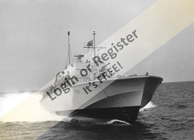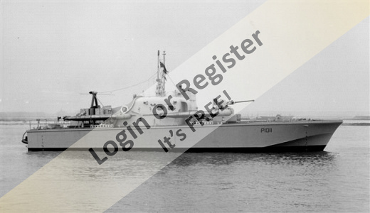
▲
⟩⟩
AlessandroSPQR
BOATSHED
Login To
Remove Ads
Remove Ads
📝 H.M.S. BRAVE BORDERER
6 years ago by 🇨🇦 Rowen ( Captain)
Captain)✧ 46 Views · 8 Likes · 4 Comments
Flag
💬 Add Comment
Just to clarify. Shipping was only 7 days to Canada, manufacture slightly longer.
Examined the hull closely and was pleased. it is dimensionally accurate and robust, but light. it had also been reinforced in strategic areas and trimmed to the correct deck line.
My many questions to Christian Sheppard – Capurro of MTBHulls were quickly and knowledgeably answered. A company I would recommend others.
Reviewing the build blogs and U Tube videos of the both the Brave and Perkasa models, shows most use either single or twin screws. The original vessel had a triple screw contra - rotating layout. Experience from others suggests the third screw just adds weight and complexity, but little to the performance. Nevertheless, it was how the Braves were built, so that was how it would be.
Christian gave several suggestions for other modelers who have built this vessel. Contacted them and was readily provided with information and advice.
The finished weight of this model is important and a target of around 6 lbs recommended for a 1:32 scale version. This is to achieve the potential performance.
Plans for drivetrain are 3 x 2835 4500kVa brushless motors, direct driving 3 x scale 3 blade 30mm screws. Decided use a single Li-Po battery for the best performance with minimum weight.
It was suggested three batteries, each powering a single motor would be the best layout. After some research, concluded this would introduce a weight penalty and was discounted.
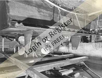
There are various ideas for the best drivetrain. Unfortunately none for triple screws. Decided the best approach would be to fit the bare hull out as planned, then try it. Leaving all the finishing features for later. A contact in Australia had already done this using a single screw layout and kindly sent pictures of his hull layout and then under test. Very informative.
The positions of the rudders, propellers and shafts are established by the scale dimensions and were permanently installed. Everything else was to be temporarily fitted, so it could be moved or replaced if necessary.


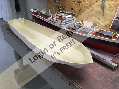

Examined the hull closely and was pleased. it is dimensionally accurate and robust, but light. it had also been reinforced in strategic areas and trimmed to the correct deck line.
My many questions to Christian Sheppard – Capurro of MTBHulls were quickly and knowledgeably answered. A company I would recommend others.
Reviewing the build blogs and U Tube videos of the both the Brave and Perkasa models, shows most use either single or twin screws. The original vessel had a triple screw contra - rotating layout. Experience from others suggests the third screw just adds weight and complexity, but little to the performance. Nevertheless, it was how the Braves were built, so that was how it would be.
Christian gave several suggestions for other modelers who have built this vessel. Contacted them and was readily provided with information and advice.
The finished weight of this model is important and a target of around 6 lbs recommended for a 1:32 scale version. This is to achieve the potential performance.
Plans for drivetrain are 3 x 2835 4500kVa brushless motors, direct driving 3 x scale 3 blade 30mm screws. Decided use a single Li-Po battery for the best performance with minimum weight.
It was suggested three batteries, each powering a single motor would be the best layout. After some research, concluded this would introduce a weight penalty and was discounted.
There are various ideas for the best drivetrain. Unfortunately none for triple screws. Decided the best approach would be to fit the bare hull out as planned, then try it. Leaving all the finishing features for later. A contact in Australia had already done this using a single screw layout and kindly sent pictures of his hull layout and then under test. Very informative.
The positions of the rudders, propellers and shafts are established by the scale dimensions and were permanently installed. Everything else was to be temporarily fitted, so it could be moved or replaced if necessary.
▲
⟩⟩
Sakibian
BOATSHED
Inkoust
mturpin013
colmax
RNinMunich
Donnieboy
marky
|
💬 H.M.S. BRAVE BORDERER
6 years ago by 🇨🇦 Rowen (
Captain)✧ 41 Views · 2 Likes
Flag
Yes, that would work. At present though am making steady progress in getting all three screws running. if that optimism is unfounded may well use your suggestion
Rowen ▲
⟩⟩
BOATSHED
RNinMunich
|
|
Login To
Remove Ads 💬 H.M.S. BRAVE BORDERER
6 years ago by 🇬🇧 onetenor (
 Sub-Lieutenant) Sub-Lieutenant)✧ 39 Views · 0 Likes
Flag
You could use just two motors for running and fit the 3rd screw to a dummy shaft for judging etc. Yes?????👍
▲
⟩⟩
No likes yet
This member will receive 1 point for every like received |
|
💬 H.M.S. BRAVE BORDERER
6 years ago by 🇨🇦 Rowen (
Captain)✧ 41 Views · 2 Likes
Flag
Hi Doug,
Thanks. Yes, there was a trim tab. To avoid your enjoyment of future epistles, all will be revealed in the fullness of time The motor control circuit is also something I am thinking about. For my current test program am going to use a simple 1 control - 1 motor. Do not know of the name Tasmanian Devil, the guy who has been very helpful is called Michael. You are probably right, think it could be "overmotored", but that will be revealed in the tests. Rowen ▲
⟩⟩
BOATSHED
RNinMunich
|
|
💬 H.M.S. BRAVE BORDERER
6 years ago by 🇩🇪 RNinMunich (
 Fleet Admiral) Fleet Admiral)✧ 41 Views · 2 Likes
Flag
Great stuff Rowen, Good progress 👍
Interesting, didn't realise they had a trim tab! Are you going to fit one? You're probably right about the battery. Usually 3 batts adding up to the same capacity (Ah) of a single weigh at least around 20-25% more. Only advantage I can see would be weight distribution; two at the sides would help to dampen rolling. Depending how you set up the ESCs and controls the 3rd motor can actually work like an overdrive or turbo 😉 You've got some mighty meaty motors there anyway so I would expect performance on two engines to be pretty good. Switch in the 3rd for 'Emergency Ahead' 'Throttles through the gate Number One'! Your contact wasn't our 'Tasmanian Devil' by any chance? 😉 A very resourceful and helpful guy👍 Ciao 😎 PS I totally agree; if the original had 3 screws (or x of anything else for that matter) then so should the model - that's what 'scale' is about ain' it😉 ▲
⟩⟩
BOATSHED
teejay
|
📝 H.M.S. BRAVE BORDERER
6 years ago by 🇨🇦 Rowen ( Captain)
Captain)✧ 44 Views · 6 Likes · 7 Comments
Flag
💬 Add Comment
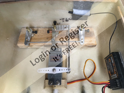
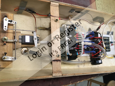
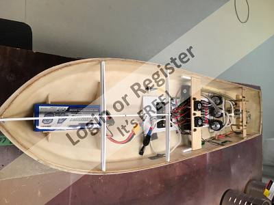
Once the rudder, propeller and shafts were installed, the position of the motors could be established. A light aluminium bracket to hold all three was fabricated and bonded to the hull. Due to the high speed capability of the brushless motors, particular attention was paid to alignment. Also kept to the shortest prop. shafts that could be fitted to avoid whipping.
Although the motor type might change, whatever is best will require a sound electrical installation as the current requirements for each brushless motor could reach 50 Amps. Wired each motor and ESC separately with its own dedicated fuse to give the maximum system protection. There is an extra fuse section allocated for auxiliary circuits, such as a cooling water pump and lights.
Will try the original planned layout of 3 x 2835 motors with 30mm propellers and a 2S Li-Po battery first. Am hoping the reduced voltage will also make these motors more tractable.
For the test program the three ESCs will be each controlled from an individual Rx channel. Once the final layout is determined, a more sophisticated and flexible control system can be installed.
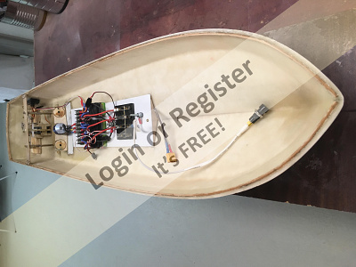
To minimize ballast, particularly around the stern, the battery will be housed as far into the bow as possible. After the test runs the final battery type, size and location can be established. To assess performance, hope to try both 2 and 3S Li-Po batteries.
Planning to reduce heat build up by fitting cooling water jackets to the motors, these are easiest to instal at this stage so the wiring or mounts are not disturbed in the future. Have not decided the layout for the water circuit yet, but this easily can be added later.
All that is needed now is the ice to melt off our local lakes so tests can commence.
Although the motor type might change, whatever is best will require a sound electrical installation as the current requirements for each brushless motor could reach 50 Amps. Wired each motor and ESC separately with its own dedicated fuse to give the maximum system protection. There is an extra fuse section allocated for auxiliary circuits, such as a cooling water pump and lights.
Will try the original planned layout of 3 x 2835 motors with 30mm propellers and a 2S Li-Po battery first. Am hoping the reduced voltage will also make these motors more tractable.
For the test program the three ESCs will be each controlled from an individual Rx channel. Once the final layout is determined, a more sophisticated and flexible control system can be installed.
To minimize ballast, particularly around the stern, the battery will be housed as far into the bow as possible. After the test runs the final battery type, size and location can be established. To assess performance, hope to try both 2 and 3S Li-Po batteries.
Planning to reduce heat build up by fitting cooling water jackets to the motors, these are easiest to instal at this stage so the wiring or mounts are not disturbed in the future. Have not decided the layout for the water circuit yet, but this easily can be added later.
All that is needed now is the ice to melt off our local lakes so tests can commence.
▲
⟩⟩
BOATSHED
MouldBuilder
Donnieboy
teejay
colmax
BigAlio
|
💬 H.M.S. BRAVE BORDERER
6 years ago by 🇨🇦 Rowen (
Captain)✧ 41 Views · 3 Likes
Flag
Thanks for your advice. Guess am stuck with the water jacket style now, will see how they work.
Was intrigued by these rubber ones though, they have an internal scroll which defines the water path. Rather like a coil. Intend to make the small ESC wire mods you and Doug recommend. Thanks ▲
⟩⟩
BOATSHED
Donnieboy
RNinMunich
|
|
Login To
Remove Ads 💬 H.M.S. BRAVE BORDERER
6 years ago by 🇦🇺 reilly4 (
 Warrant Officer) Warrant Officer)✧ 40 Views · 2 Likes
Flag
Hi Rowen,
I have had water cooling on all my patrol boats running at 12Volts, whether brushed or now brushless. For the brushed motors I have used aluminium tube coils with water pickups between the propellers and rudders. I did try water jackets a couple of times but found too much friction loss and therefore lack of flow. For the newer brushless outrunners I use a brass tube soldered to a brass plate across the front of the motor fitted between it and motor mounting bracket. I agree with Doug with regards to the disconnection of the red wires on the ESC's. This is now common practice, especially if you have an external receiver battery. 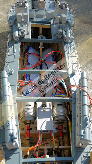
▲
⟩⟩
BOATSHED
Donnieboy
|
|
💬 H.M.S. BRAVE BORDERER
6 years ago by 🇩🇪 RNinMunich (
Fleet Admiral)✧ 40 Views · 2 Likes
Flag
Hi Rowen,
snag with the ESCs is that bY connecting all 3 red leads to the the RX you are shorting the outputs of all the Battery Eliminator circuits together. If they are not protected by fast diodes you may do serious damage to the ESCs 😡 The RX only needs one supply anyway. if you are going to use a separate RX battery then DEFINITELY disconnect all 3 ESC red leads! Cheers Doug 😎 ▲
⟩⟩
BOATSHED
Donnieboy
|
|
💬 H.M.S. BRAVE BORDERER
6 years ago by 🇨🇦 Rowen (
Captain)✧ 40 Views · 1 Like
Flag
Thanks all for the responses.
Donnieboy - have thought out the plumbing, which is simplified by using a cooling pump. See future episodes! Doug - appreciate the concern regarding the red ESC wires. Have been trying to understand the rationale behind that theory. if all ESCs share a common input voltage, i.e. from one battery, what would the connection of multiple red wires do? Can understand if there were several unique power sources, but that is not the case here. Perhaps with your electronics background you can explain. Colmar - Used the angle on the scale drawing. if it were good enough for Vosper, should be good enough for me! Think it close to 7 degrees anyway. Think short shafts with oilers should help. Have heard of bushings running dry and seizing with these high speed motors. The initial props are scale versions of the originals. Rather suspect they will not prove to be ideal. Have purchased some 2 blade racing style props for a future test. They have a much coarser pitch and are designed for high speed motors. Intend to use plastic props initially as they are cheap enough to experiment with. Perhaps others have a comments on the cavitation question?. Incidentally, this is my first high speed boat too, but there is much of information on both this web site and Model Boat Mayhem for guidance. Posting questions always generates useful information. Look widely though at all types of fast models, MTBs, RAF launches, E Boats etc. - it has all been done before! ▲
⟩⟩
BOATSHED
|
|
💬 H.M.S. BRAVE BORDERER
6 years ago by 🇬🇧 colmax (
 Recruit) Recruit)✧ 40 Views · 1 Like
Flag
Hi - This will be my first fast boat build and thoroughly enjoying yours :o) The layout is superb. Great advice keeping the prop shafts short which would have completely escaped me! I also note the long oilers added. Also, is there a particular angle for setting them to (7 degrees I've read)? As for minimising cavitation is there a general preference for props?
Sorry if my Q's are basic but really quite new to it all. ▲
⟩⟩
BOATSHED
|
|
💬 H.M.S. BRAVE BORDERER
6 years ago by 🇩🇪 RNinMunich (
Fleet Admiral)✧ 40 Views · 1 Like
Flag
Neat installation 👍👍
Don't forget to disconnect two of the red supply leads from the RX if the ESCs have BEC !!! 😲 Cheers Doug 😎 ▲
⟩⟩
BOATSHED
|
|
💬 H.M.S. BRAVE BORDERER
6 years ago by 🇨🇦 Donnieboy (
Warrant Officer)✧ 39 Views · 0 Likes
Flag
Nice installation of the electrics.Easy access.It might be better to plan the water cooling right now just in case something gets in the way.
▲
⟩⟩
No likes yet
This member will receive 1 point for every like received |
📝 H.M.S BRAVE BORDERER
6 years ago by 🇨🇦 Rowen ( Captain)
Captain)✧ 45 Views · 7 Likes
Flag
💬 Add Comment
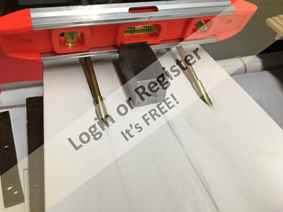
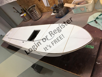
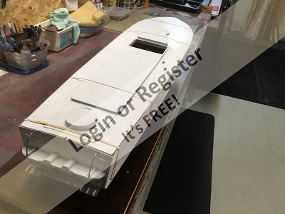
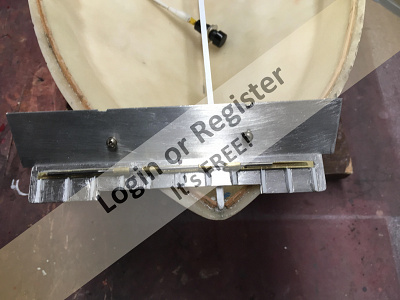
Whilst waiting for the ice to melt, decided to make up the deck and transom flaps.
The deck was made from styrene sheet, again for lightness. Made the deck beams out of square styrene sections to avoid traditional, heavy, full width bulkheads. Hoped the stiff MTBH hull would resist twisting without bulkheads. First impressions are that this is the case and when the deck is finally bonded to the hull, should be even better..
The transom flap was made from thin aluminium plate and added simulated stiffener ribs in styrene.
Understand that about a 2 degree flap down inclination works best on this model.
My original plan was to operate the flap using a servo with another radio channel, however once the best plane is achieved it is unlikely the flaps will need further adjustment. Unlike the real vessel, the operating weight will remain fairly constant. So, abandoned the servo idea to use adjustable bottle-screws instead. The flap angle can still be adjusted, but not in motion. These screws are much simpler, lighter and cheaper than a servo.
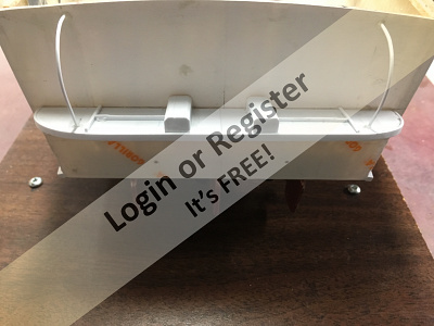
One challenge was to make the very small hinges required for an adjustable flap. After much thinking and investigation, decided the simplest and neatest way would be to use thin, self adhesive aluminium tape, as used on forced air heating ducts. Would stick the self adhesive surface to the underside of the flap and then onto the inside face of another thin aluminium sheet, which could then be fitted to the transom using double sided tape and small screws.
This seems to work so far, it also avoids drilling through holes into the transom .

The deck was made from styrene sheet, again for lightness. Made the deck beams out of square styrene sections to avoid traditional, heavy, full width bulkheads. Hoped the stiff MTBH hull would resist twisting without bulkheads. First impressions are that this is the case and when the deck is finally bonded to the hull, should be even better..
The transom flap was made from thin aluminium plate and added simulated stiffener ribs in styrene.
Understand that about a 2 degree flap down inclination works best on this model.
My original plan was to operate the flap using a servo with another radio channel, however once the best plane is achieved it is unlikely the flaps will need further adjustment. Unlike the real vessel, the operating weight will remain fairly constant. So, abandoned the servo idea to use adjustable bottle-screws instead. The flap angle can still be adjusted, but not in motion. These screws are much simpler, lighter and cheaper than a servo.
One challenge was to make the very small hinges required for an adjustable flap. After much thinking and investigation, decided the simplest and neatest way would be to use thin, self adhesive aluminium tape, as used on forced air heating ducts. Would stick the self adhesive surface to the underside of the flap and then onto the inside face of another thin aluminium sheet, which could then be fitted to the transom using double sided tape and small screws.
This seems to work so far, it also avoids drilling through holes into the transom .
▲
⟩⟩
BOATSHED
Inkoust
Colin H
BigAlio
RNinMunich
colmax
Donnieboy
📝 H.M.S. BRAVE BORDERER
6 years ago by 🇨🇦 Rowen ( Captain)
Captain)✧ 45 Views · 7 Likes
Flag
💬 Add Comment
An unexpected opportunity arose to try the unfinished hull in a small pool. Whilst the performance envelope could not be explored, was able to try and measure operating parameters and get a “feel” for the model.
Used an electronic scale and a combination voltmeter/ammeter/wattmeter to measure propeller thrust /bollard pull and motor power requirements. if it is necessary to fit different drivetrain components, or a 3S cell this will serve as the baseline.
The model floated levelly and well above the waterline. At about 8 volts the motors drew around 20 amps each at full speed; so only about 35% of the potential output capacity was being used. Tested each motor individually and measured the bollard pull at just over 2 lbs. A considerable amount of spray and wash was created making stable readings difficult. For further testing, will add ballast at the stern to hold the propellers further underwater. Should help reading stability.
Currently using 20 A fuses; which as one failed seem marginal. For sustained use think 25 or 30 Amp better. With these high-speed, low torque motors establishing the “dry” propeller rotation is deceptive. Found one motor to be reversed! Nevertheless, the model accelerates quickly and is sensitive to engine speed movements.
Left the pool with a list of modifications to make before assessing the installation properly on an adequate body of water. Some conclusions can be made though. if it is necessary to add a second cell this needs to be located around midships, not in the bow or stern. Still hoping a 3S cell will not be necessary and that 2S may be adequate.
The suggestion to do testing using the bare hull with a minimum of detail was a good one. For a models with a sophisticated power train think this is a good approach. Nothing worse that finishing a boat just to find the performance disappointing, then have to to rip it apart to make major modifications or adjustments!
▲
⟩⟩
BOATSHED
MouldBuilder
Donnieboy
doghouse
watson220
SelwynWilliams
RNinMunich
📝 H.M.S. BRAVE BORDERER
6 years ago by 🇨🇦 Rowen ( Captain)
Captain)✧ 43 Views · 5 Likes
Flag
💬 Add Comment
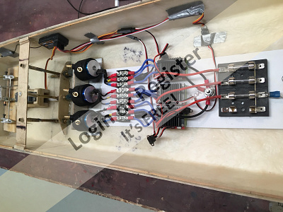
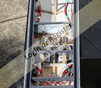
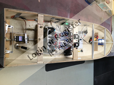
From the brief pool test, had decided that the motors could be susceptible to overheating, so connected up the water jacket cooling system and powered it with a small pump. Did not leave enough space to fit a scoop behind a propeller anyway, but prefer the positive action of a pump though.
From feeling the ESCs, was also concerned they could overheat within a confined space such as the hull. Mounted a couple of small fans in a bridge structure above the ESCs, along with the ESC switches. Not sure either of these cooling modifications are really required, but erred on the side of caution. Final weight of the hull, with all electrics (apart from battery) comes to 5.05 lbs. Looks like will not achieve the target weight of 6 lbs, but am hopeful will be able to get close to it..
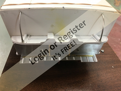
Built the deck up with gun mount bases and a removable decking over the engine area. This limits access to the internals; so will not fit it permanently until the test program is complete and all modifications incorporated.
Have now reached a point where any further work will be to start finishing the model, unless drivetrain modifications are required. Have thus decided to leave it until after the first open water test date. This will be in late May as am away until then.
From feeling the ESCs, was also concerned they could overheat within a confined space such as the hull. Mounted a couple of small fans in a bridge structure above the ESCs, along with the ESC switches. Not sure either of these cooling modifications are really required, but erred on the side of caution. Final weight of the hull, with all electrics (apart from battery) comes to 5.05 lbs. Looks like will not achieve the target weight of 6 lbs, but am hopeful will be able to get close to it..
Built the deck up with gun mount bases and a removable decking over the engine area. This limits access to the internals; so will not fit it permanently until the test program is complete and all modifications incorporated.
Have now reached a point where any further work will be to start finishing the model, unless drivetrain modifications are required. Have thus decided to leave it until after the first open water test date. This will be in late May as am away until then.
▲
⟩⟩
BOATSHED
MouldBuilder
Donnieboy
Inkoust
figtree7nts
📝 H.M.S BRAVE BORDERER
6 years ago by 🇨🇦 Rowen ( Captain)
Captain)✧ 40 Views · 2 Likes
Flag
💬 Add Comment
Looks like everything is set for the first open water test. Sun is shining, ice has gone and water smooth.
Intention is to start the open water test program with a repeat of the pool test, except this time with everything wired correctly; the load cell positioned so the “pull” is more horizontal and ballast available to hold the propellers underwater if necessary. Hope these improvements help reading stability.
To modify the “pull” arrangements, wrapped a light cord around the propeller shaft struts and fed the loose end above the transom shelf and out over the stern. The load cell was hooked into this and then tied to a fixed grating on the pond side.
Started by measuring the electrical requirements for each of the three motors and the propeller bollard pull, using the 2 S battery. Found the bollard pull was up slightly at almost 3 lbs per propeller. Probably because they were now held at a greater depth in the water. Also blew several 20A fuses, so fitted 30, which seem to work.
A series of runs showed adequate performance with plenty of spray, although the bow did not lift much onto the plane. The forefoot did raise almost above the water surface.
Then tried a 3S battery. Although this was much heavier, the performance improved dramatically. The bollard pull was up to almost 18 lbs per shaft. The bow still did not lift much to a plane, although the forefoot was almost clear of the water at full speed. The battery was located just back from the bow, so it is suspected that it held the bow down. The impact of the transom flap down angle could also hold the bow down, but have decided to leave as is for the time being and avoid the temptation of making too many adjustment at once.
Whilst it is still too early to draw definite conclusions, it seems as if a 3S battery will be required.
The model sustained some slight damage due to the test arrangements, so will repair that and also fit the 2 bladed Hi Speed propellers. Will then repeat the program and report. Should be able to draw some definite conclusions then on the best power train.
Neither of the batteries used, neither the 2 S nor the 3S are ones I would choose for this model. As a result the capacities and weights are not ideal. That must also be remembered in future deliberations.
▲
⟩⟩
BOATSHED
Donnieboy
📝 H.M.S BRAVE BORDERER
6 years ago by 🇨🇦 Rowen ( Captain)
Captain)✧ 41 Views · 3 Likes
Flag
💬 Add Comment
itted 2 x two bladed 35 mm “hi-speed” propellers to the outer shafts only as these are the easiest to change. Can also use the centre shaft measurements as a check of the previous figures as it is unchanged.
With these propellers the current draw and bollard pull both increased. Subjectively, think she was also slightly faster, but the speed exceeds scale speed anyway.
The increased load on one of the 2 bladed props wiped the blades off and several 30 A fuses on various motor circuits blew.
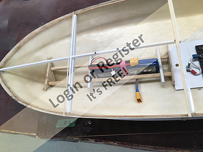
Originally, the battery was fitted as far forward as possible to hold the bow down – some thing it seems to have achieved! Decided to remove the forward battery location frame and replace it with one which will allow the battery to be positioned anywhere between the bow and the centre of the model. The battery can now be located where the best plane is achieved. Once the correct battery is fitted the final location will be determined. This frame movement will also allow adjustments for any weight gained during final finishing.
Whilst the idea of using a load cell and ammeter/wattmeter to measure bollard pull and motors loads sounds logical, it is fraught with challenges. The vessel both bucks and the readings fluctuate wildly under load making getting steady, consistent results difficult.
Off now to cogitate over the results and decide a path forward.
With these propellers the current draw and bollard pull both increased. Subjectively, think she was also slightly faster, but the speed exceeds scale speed anyway.
The increased load on one of the 2 bladed props wiped the blades off and several 30 A fuses on various motor circuits blew.
Originally, the battery was fitted as far forward as possible to hold the bow down – some thing it seems to have achieved! Decided to remove the forward battery location frame and replace it with one which will allow the battery to be positioned anywhere between the bow and the centre of the model. The battery can now be located where the best plane is achieved. Once the correct battery is fitted the final location will be determined. This frame movement will also allow adjustments for any weight gained during final finishing.
Whilst the idea of using a load cell and ammeter/wattmeter to measure bollard pull and motors loads sounds logical, it is fraught with challenges. The vessel both bucks and the readings fluctuate wildly under load making getting steady, consistent results difficult.
Off now to cogitate over the results and decide a path forward.
▲
⟩⟩
BOATSHED
Donnieboy
RNinMunich
📝 H.M.S BRAVE BORDERER
6 years ago by 🇨🇦 Rowen ( Captain)
Captain)✧ 45 Views · 7 Likes · 1 Comment
Flag
💬 Add Comment
Now the spray has settled have assessed these first tests; have also reviewed various pictures and U Tube videos of the Brave and Pekasas in operation. The actual vessels look to plane rather like mine, whilst some model bows lift up until a significant length of keel is exposed.
Anyway, have been able to draw some conclusions:
1) Moved the battery towards the stern and, at speed, the forefoot lifts slightly clear of the water. The plane is now almost flat. The battery is not well positioned when near the bow.
2) The 2S battery used was a 4000mAh 30C; suspect this battery does not have the capacity to operate the model. Every motor will run up smoothly until a second one is operated. The first motor then “stutters” and a fuse might blow, this could be indicative of a power surge. Any comments from the electronic experts among the group would be appreciated.
3) The 3S battery was 10,500mAh and 40C; with this battery all three motors can be run at full speed together and fuses do not blow. it was also very heavy at 1700g, holding the model down.
4) The motors are 4500 kV. On refection, think a slower motor around, perhaps 2000 kV would have been a better choice.
5) Would concur with comments by others that a simple single or two bladed propeller layout for this model is probably best - that is unless you want to capture the true scale layout. The centre propeller seems to have little effect on overall performance, although it will power the model quite nicely when operating by itself. Have had several suggestions about how best to use the centre propeller. Will think about them and decide later how to do this when I start to finish the model.
6) The 2 blade Hi – speed propellers both increased performance and current draw. The model is more than fast enough with the original scale layout.
7) Will purchase a lighter, 3 S battery as that seems the best choice for performance and weight.
8) Testing using the bare hull with a minimum of detail worked well. For a models with a complex power train, this is a good approach as access to the internals can be gained easily. Nothing worse that finishing a boat carefully just to find the performance disappointing. Then having to to rip it apart to make major modifications or adjustments!
▲
⟩⟩
boaty
doghouse
BOATSHED
mturpin013
figtree7nts
Donnieboy
RNinMunich
|
💬 H.M.S BRAVE BORDERER
6 years ago by 🇩🇪 RNinMunich (
Fleet Admiral)✧ 40 Views · 3 Likes
Flag
Evenin' Rowen,
So far so good, nice job👍 Let me go through your comments one by one😉 1) "Moved the battery towards the stern and, at speed, the forefoot lifts slightly clear of the water. The plane is now almost flat. The battery is not well positioned when near the bow." Battery in the bow is almost always bad news🤔 too much weight forward of the CoG or natural balance point when planing. 2) "The 2S battery used was a 4000mAh 30C; suspect this battery does not have the capacity to operate the model. Every motor will run up smoothly until a second one is operated. The first motor then “stutters” and a fuse might blow, this could be indicative of a power surge. Any comments from the electronic experts among the group would be appreciated." First the battery: you may be right. Especially with 3 x4500 kV motors Since you are using 3 ESCs how about feeding each one from a slightly smaller (lower weight) battery? Precondition of course is that all three are equally charged to the same voltage and capacity AND have the same (or very very similar) internal resistance! Complicates the issue of course and motors with a lower kV rating and one power source may well be the better solution😉 Second the 'stutter': How and when did you switch in the second motor? If the first was still at 'Full Ahead', i.e. 'Pedal to the metal!, I might expect the battery voltage to dip and then recover with the sudden additional load and a sharp rise in total current drawn. But no particular excuse for a sudden current rise in the first motor ! Where was the fuse that blew? I suspect in the primary supply lead from the single battery🤓 since with brushless motors you can't fit individual fuse in their supply leads like you can with a brushed motor. BUT you can to the ESCs feeding them!!! You can't get a power surge from a battery, not like a surge on the mains network due to lightning etc! But you can get a voltage dip and recovery if you suddenly present it with an additional load😲 3) "The 3S battery was 10,500mAh and 40C; with this battery all three motors can be run at full speed together and fuses do not blow. it was also very heavy at 1700g, holding the model down." All run up together to full speed or 'switched in' as described above? There's a big difference between a gradual increasing of load on a power source and a sudden step increase! 4) "The motors are 4500 kV. On refection, think a slower motor around, perhaps 2000 kV would have been a better choice." I did think at the outset that 3 x 4500kV was perhaps a little ambitious😲 2000 - 2500 sounds much better, and more controllable👍 Then you could also get good performance results with a single battery of capacity lower and weight 👍 The function of the third (centre) motor for 'action speed' would also be more pronounced👍 5) "Would concur with comments by others that a simple single or two bladed propeller layout for this model is probably best - that is unless you want to capture the true scale layout. The centre propeller seems to have little effect on overall performance, (see above re 4500kV motors- Doug😉) although it will power the model quite nicely when operating by itself. Have had several suggestions about how best to use the centre propeller. Will think about them and decide later how to do this when I start to finish the model." As a 'Scale Purist' (as far as my skills and tools allow!) personally I would frown on the use of 2 blade props, much less only a single prop. Do that in a fictitious power boat if you will, but for 'Brave Borderer' ? 😡 Do her justice please😉 Many three screw (😲) boats (including the full size originals of this era) only used the third motor for additional manoeuvring speed in action situations. My personal experience of FACs (Fast Attack Craft) and FPBs (Fast Patrol Boats) over the last three decades shows me that the three screw configuration has been largely dropped, especially since the introduction of much more powerful engines such as improved diesels and gas turbines. Many use a combination of diesel, for cruising, and gas turbine for 'action speed', so called CODAG, COmbined Diesel And Gas turbine. 6) "The 2 blade Hi – speed propellers both increased performance and current draw. The model is more than fast enough with the original scale layout." As I believe the 2 blade props were of larger diameter (and perhaps also of larger pitch) than the 3 bladers the higher current draw is a logical conclusion! Stick with the scale config! 👍👍👍 7) "Will purchase a lighter, 3 S battery as that seems the best choice for performance and weight." 👍 but don't overdo it to the other extreme by reducing weight and therefore capacity too much😲 You want a decent sailing time don't you? 8) "Testing using the bare hull with a minimum of detail worked well. For a models with a complex power train, this is a good approach as access to the internals can be gained easily. Nothing worse that finishing a boat carefully just to find the performance disappointing. Then having to to rip it apart to make major modifications or adjustments!" Heartily agree 👍👍👍 Bon chance mon ami😊 ▲
⟩⟩
BOATSHED
Donnieboy
Rowen
|
📝 H.M.S. BRAVE BORDERER
6 years ago by 🇨🇦 Rowen ( Captain)
Captain)✧ 51 Views · 6 Likes · 7 Comments
Flag
💬 Add Comment
Decided to retry with the 2S battery and the original scale style propellers. Concluded that the speed is fine, especially in the windy conditions encountered and in a small pool that limited acceleration. The model had a very flat plane, must adjust the transom flap angle to see what effect that has. The forefoot did not rise much from the water surface.
Was frustrated by the “stutter” referred to in the last blog, noticed this occurred on the two out shafts only and when the starboard was operated after the port was running. Swopped the starboard motor over with the centre one to see what effect it would have. As started to remove the motor noted that a connector was not tight and that the screw had corroded. Exchanged motors, removed all connectors then cleaned and refitted using a water resistant lubricant. The stutter seemed cured.
Another lesson learnt, when dealing with these high currents every connection is tested and all defects exposed.
The opportunity to retest using a 3S battery arose so installed it, all worked fine on the bank. Put the model in the water and a major short occurred. 2 fuses blew and about 6” of wiring melted and burnt through the insulation. At least there was no hull damage!
Did an inquest and, apart from the damage described, also found the starboard ESC and motor had failed. These were the ones where the “stutter” originated, but cannot see any correlation between the two problems.
Discussed the model with some of fellow scale modelers and concluded that the 4500kV motors are unsuitable for the scale propellers used. Every suggestion points toward motors in the 1 – 2000kV range. As now needed to obtain a new motor and ESC, decided to reequip both outer shafts with 2000kv motors and water cooled ESCs.
Felt modifying these outer shafts would allow assessment of this new drivetrain combination, could then decide what approach to take with the centre shaft. Due to the mounting and driveshaft arrangement, the choice of motors was restricted to 28mm O/D with a 1/8” shaft size. Unfortunately, suitable items are on back-order from Hong Kong, so there will be no further updates for a while.
▲
⟩⟩
doghouse
boaty
BOATSHED
bikerjohn57
Donnieboy
mturpin013
|
💬 H.M.S. BRAVE BORDERER
5 years ago by 🇨🇦 Rowen (
Captain)✧ 48 Views · 1 Like
Flag
Thanks. Agree, with the wisdom of hindsight this wound have been s better appproach. Anyway, have learnt a lot from this project and enjoyed it
▲
⟩⟩
BOATSHED
|
|
Login To
Remove Ads 💬 H.M.S. BRAVE BORDERER
5 years ago by 🇺🇸 bubbletop409 (
Recruit)✧ 48 Views · 2 Likes
Flag
You would actually be better off with motors that have a KV rating of less than 1000. I have a 48" Elco PT with three 780 KV's on three cell lipo's, 40mm 3 blade props, scale planning speed is obtainable at approximately 45% throttle. Very little load on motors, no cooling necessary on motors or ESC's.
You will also find low speed operation much more manageable. ▲
⟩⟩
Donnieboy
RNinMunich
|
|
💬 H.M.S. BRAVE BORDERER
6 years ago by 🇨🇦 Rowen (
Captain)✧ 48 Views · 1 Like
Flag
Hi. Thanks for your comments.
Before I started the BB did some canvassing of the net to find other builders. The drivetrain remarks were particularly interesting. The consensus seems to be that building three screws, as is scale and as I am determined to do, is the most complex and that for performance it is better using either single or two. Once deviating from scale bigger propellers also work better. I have rather limited my options with being determined to capture the original layout though. The vessel is being scratch built on a hull from MTBHulls, of which I am well pleased. The HK source is HobbyKing, often find their products are on backorder, but usually only take a few days to arrive. in this case have been advised it will be rather longer. ▲
⟩⟩
BOATSHED
|
|
💬 H.M.S. BRAVE BORDERER
6 years ago by 🇬🇧 bikerjohn57 (
 Master Seaman) Master Seaman)✧ 65 Views · 1 Like
Flag
If its of any help I run a all wood Perkasa with one motor (came from a old battery power tool) powered with a lead acid 12 volt, so as you can imagine its heavy.
But she will plane as per any photo you can find on the NET. 😊 You state that you are waiting for parts from HK, is your BB a Hooben model ?. I purchased one of these and found the moulding of the transom to be atrocious and the company's customer service to be non existent. ▲
⟩⟩
BOATSHED
|
|
💬 H.M.S. BRAVE BORDERER
6 years ago by 🇩🇪 RNinMunich (
Fleet Admiral)✧ 48 Views · 1 Like
Flag
Hi Rowen, you could always use small cable ties to hold the ESC wires down. The motor wires then look after themselves 😉
Look forward to some pics / vids of the Teakwood in action👍 G'night, Doug 😎 ▲
⟩⟩
BOATSHED
|
|
💬 H.M.S. BRAVE BORDERER
6 years ago by 🇨🇦 Rowen (
Captain)✧ 49 Views · 2 Likes
Flag
Doug,
Thanks for the comments, you are probably right on all counts. The loose connection was more than likely caused by moving the wire to get it lined up once installed and the movement released it slightly. Rather like the terminal block idea though as it holds the wires in place, can now guard against looseness and corrosion by careful assembly. However, am mulling over the gold connectors suggestion, probably have some weeks to come to a conclusion! They are much lighter than the block too. The motors are on back order, am now resigned to waiting for them. it does give the opportunity to park the Brave and get some running time on my Teakwood, which has hardy moved this year. Rowen ▲
⟩⟩
BOATSHED
RNinMunich
|
|
💬 H.M.S. BRAVE BORDERER
6 years ago by 🇩🇪 RNinMunich (
Fleet Admiral)✧ 48 Views · 1 Like
Flag
Hi Rowen, Bad luck🤔
Not necessarily a short, maybe just very high current draw due to the 4500kV motors and a dodgy connection adding resistance. In the wet stuff you have of course a load on the propellers which you don't have on the bench/bank, hence the higher current draw through the ESCs. I did wonder before about the 3 x 4500kV !! Since I went brushless I always use only 3.5 or 4mm gold bullets to connect them to the ESCs. Suggest you do the same and remove the corrosion susceptible screw connections.😲 Surprised the motors weren't available😲 I recently bought some, also 28mm,and some EScs for my PTB and they were here in 4 days! Oops, sorry, did I buy the one's you wanted 🤔 ▲
⟩⟩
BOATSHED
|


Login To
Remove Ads
Remove Ads