Join Us On Social Media!

|

|

|
Download The App!
Login To
Remove Ads
Remove Ads
Login To
Remove Ads
Remove Ads
Model Boats Website
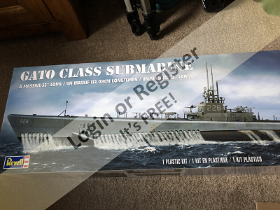
Revell Gato Class Submarine Conversion.
16 Posts · 6 Followers · 156 Photos · 52 Likes
Began 5 years ago by
 Hungary
Follow This Thread
Not currently following
> Click to follow
> Click to follow
Latest Post 4 years ago by
| Oldest posts shown first (Show Newest First) | (Print Booklet) |
📝 Revell Gato Class Submarine Conversion.
5 years ago by 🇭🇺 MouldBuilder ( Vice Admiral)
Vice Admiral)✧ 17 Views · 4 Likes · 8 Comments
Flag
💬 Add Comment
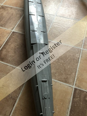
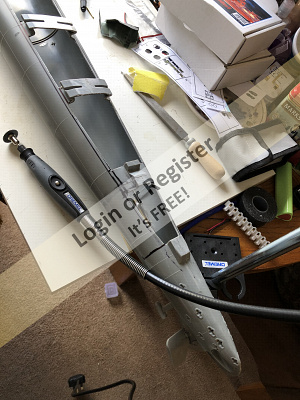
I am about to start the most ambitious project to date. This one will be running alongside the three others currently on the go, The Police Boat which is nearly completed, The Dusseldorf Fire Boat which is well underway and the PTB upgrade.
My intention is to change this Revell model into a static dive radio controlled Submarine. I am lucky that Martin555 has agreed to help whenever I get stuck which will be invaluable since he has already almost completed the same.
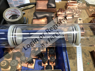
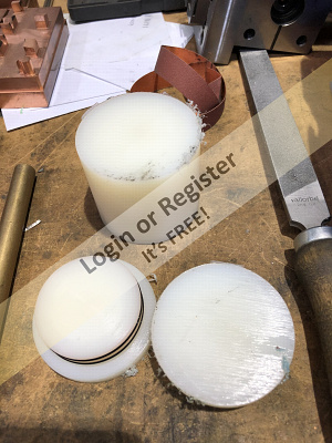
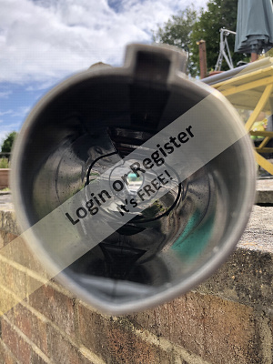
I started by purchasing the model from Amazon for less than £50. I have also purchased the water tight tube for the electronics. I will make the end caps and sealed internal plugs from some 80mm diameter nylon I had at work. It will now come in handy that I am a toolmaker and have a considerable array of machines at my disposal.
I will turn the plugs next week and find suitable o rings.
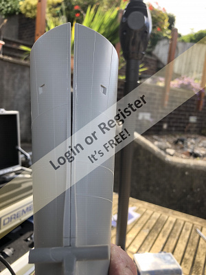
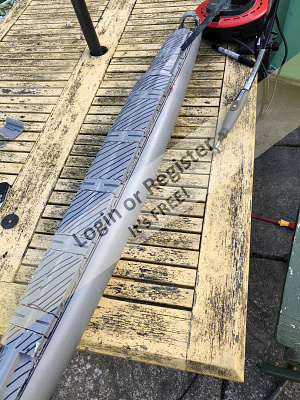
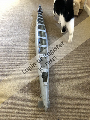
I have started to prepare the hull. There is an enormous amount of work required to adjust the standard kit. A lot of cutting and drilling.
I have prepared the split lines and glued in the alignment pegs.
I have ordered suitable shafts and propellers from the USA. They should be here in a couple of weeks.
Next job is to stick the two halves together and start the cutting.

My intention is to change this Revell model into a static dive radio controlled Submarine. I am lucky that Martin555 has agreed to help whenever I get stuck which will be invaluable since he has already almost completed the same.
I started by purchasing the model from Amazon for less than £50. I have also purchased the water tight tube for the electronics. I will make the end caps and sealed internal plugs from some 80mm diameter nylon I had at work. It will now come in handy that I am a toolmaker and have a considerable array of machines at my disposal.
I will turn the plugs next week and find suitable o rings.
I have started to prepare the hull. There is an enormous amount of work required to adjust the standard kit. A lot of cutting and drilling.
I have prepared the split lines and glued in the alignment pegs.
I have ordered suitable shafts and propellers from the USA. They should be here in a couple of weeks.
Next job is to stick the two halves together and start the cutting.
▲
⟩⟩
Scratchbuilder
mturpin013
Martin555
stevedownunder
|
💬 Re: Revell Gato Class Submarine Conversion.
5 years ago by 🇭🇺 MouldBuilder (
Vice Admiral)✧ 14 Views · 1 Like
Flag
Hi Bill.
You have made a really nice looking model. This project will take a while but I am looking forward to it. The propellers, shafts and joints can be found on ebay. The item number is 273490619808. The seller is rc-sub-workshop. They are a little expensive but they do come with all of the required parts. I will let you know what they are like when they arrive. They are coming from Hong Kong I think. Peter.😊 ▲
⟩⟩
Martin555
|
|
Login To
Remove Ads 💬 Re: Revell Gato Class Submarine Conversion.
5 years ago by 🇬🇧 Martin555 (
 Fleet Admiral) Fleet Admiral)✧ 13 Views · 0 Likes
Flag
Nice model.
Martin. ▲
⟩⟩
No likes yet
This member will receive 1 point for every like received |
|
💬 Re: Revell Gato Class Submarine Conversion.
5 years ago by 🇬🇧 Scratchbuilder (
Vice Admiral)✧ 17 Views · 4 Likes
Flag
Hi.
Good luck with the Gato Submarine.A great project. I built one from the same kit some three years ago although she is only a surface boat. I would be interested to know where you got the shafts from. I turned my own at home and also made the A brackets, adapted the original rudder etc. I attach a few pictures of her on the pond. Looking forward to reading more on your progress. Regards Bill👍 


▲
⟩⟩
Inkoust
RNinMunich
MouldBuilder
Martin555
|
|
💬 Re: Revell Gato Class Submarine Conversion.
5 years ago by 🇭🇺 MouldBuilder (
Vice Admiral)✧ 14 Views · 1 Like
Flag
The joints will be in the hull space along with the universal joints for the motor connections....I hope.
I have just drawn the motor position layout and it looks like two 25mm diameter geared motors fit the bill. I would like to know what rpm I should aim for. I would have thought that speed of the boat was fairly unimportant. slow is good, but torque would be. I was thinking around 500rpm at 6 volts. We will see. Thoughts would be welcome from more experienced builders. The inside of the Water Tight Compartment will be 66mm. This allows for both motors to be almost entirely below the tube centre line. 
▲
⟩⟩
Martin555
|
|
💬 Re: Revell Gato Class Submarine Conversion.
5 years ago by 🇳🇿 jbkiwi (
Fleet Admiral)✧ 16 Views · 3 Likes
Flag
Magnetic rod joints, neat idea! (miniatures of magnetic table mechanism would be cool) depending on the magnets you might need to come up with a separating tool (neodymium magnets especially would be a mission in a tight space!) or will the joints be out in the hull space?
▲
⟩⟩
mturpin013
MouldBuilder
Martin555
|
|
💬 Re: Revell Gato Class Submarine Conversion.
5 years ago by 🇭🇺 MouldBuilder (
Vice Admiral)✧ 16 Views · 3 Likes
Flag
Hi jb.
This is all new to me as well. There will be a sealed tube about 50cm long inside sealed with o ringed bungs at each end with further sealed barriers inside to hold the flotation bladder. I have the tube and the material for the bungs which I will start soon. The tube should be relatively easy to remove as I will use magnetic joints for the operating rods. This project will take some time and will be quite expensive.😊 ▲
⟩⟩
mturpin013
Martin555
jbkiwi
|
|
💬 Re: Revell Gato Class Submarine Conversion.
5 years ago by 🇬🇧 Martin555 (
Fleet Admiral)✧ 15 Views · 2 Likes
Flag
Hi Peter,
It a bit of a challenge but you will get there. Good luck. Martin. ▲
⟩⟩
mturpin013
MouldBuilder
|
|
💬 Re: Revell Gato Class Submarine Conversion.
5 years ago by 🇳🇿 jbkiwi (
Fleet Admiral)✧ 15 Views · 2 Likes
Flag
That's an impressive piece of plastic! How will you service the internals etc once glued together, o-ringed hatches or is the tube a complete drop in/removable module ? Must be a job trying to keep everything dry in subs, bad enough with racing boats! Certainly will save a lot of hull construction work doing it with the kit. A bonus would be that gluing bits to this material is easy and it's reasonably durable.
▲
⟩⟩
mturpin013
MouldBuilder
|
Login To
Remove Ads
Remove Ads
📝 Joining the fuselage.
5 years ago by 🇭🇺 MouldBuilder ( Vice Admiral)
Vice Admiral)✧ 14 Views · 1 Like · 23 Comments
Flag
💬 Add Comment
Just a small update today as I have been spending most of my available time on the Dusseldorf.
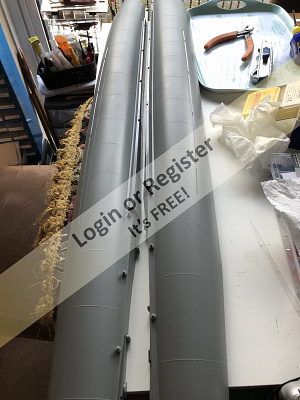
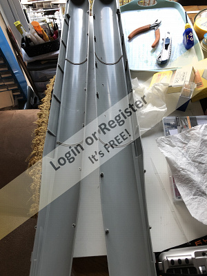
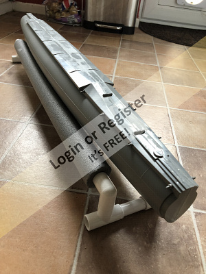
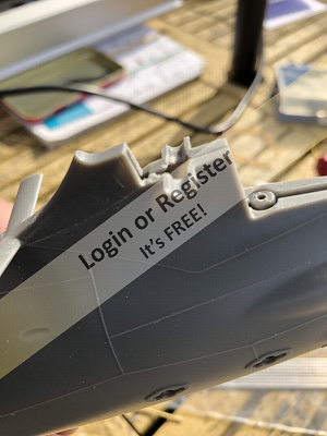
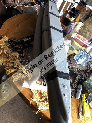
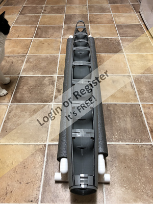
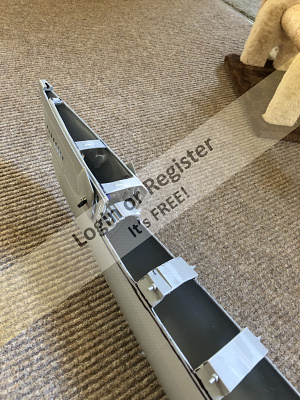
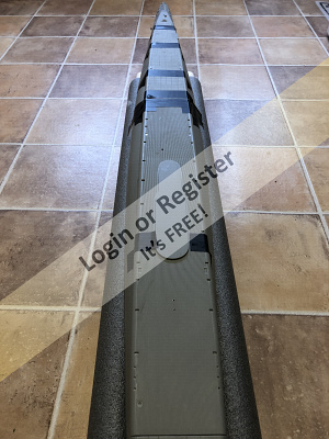
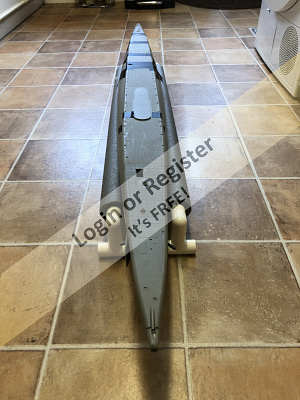
Over the past week I have glued the two main fuselage halves together and then tidied up the joints.
There is a lot of interest in Submarines in the USA and one particular modeler has created some very helpful video blogs of his build. I have been watching these which has taken up several hours. I am now getting an idea as to how difficult this is going to be.
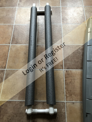
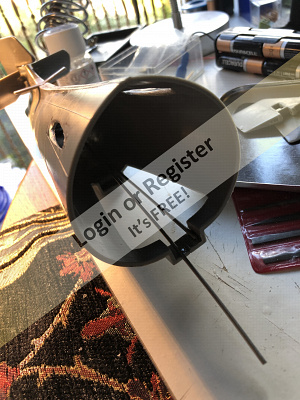
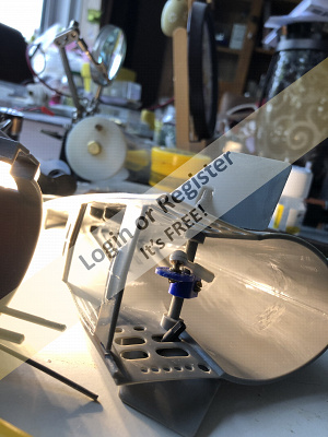
Within the videos, you can see a very useful stand has been constructed to aid the build. I just had to copy it using toilet overflow parts. The sub rotates nicely on the rollers.
I have to try to find some materials for the retracting bow planes next which I think will be my first real challenge. Next update might take a few weeks.😀
Over the past week I have glued the two main fuselage halves together and then tidied up the joints.
There is a lot of interest in Submarines in the USA and one particular modeler has created some very helpful video blogs of his build. I have been watching these which has taken up several hours. I am now getting an idea as to how difficult this is going to be.
Within the videos, you can see a very useful stand has been constructed to aid the build. I just had to copy it using toilet overflow parts. The sub rotates nicely on the rollers.
I have to try to find some materials for the retracting bow planes next which I think will be my first real challenge. Next update might take a few weeks.😀
▲
⟩⟩
Martin555
|
💬 Re: Joining the fuselage.
5 years ago by 🇭🇺 MouldBuilder (
Vice Admiral)✧ 14 Views · 1 Like
Flag
Fairy Dust.
▲
⟩⟩
RNinMunich
|
|
Login To
Remove Ads 💬 Re: Joining the fuselage.
5 years ago by 🇩🇪 RNinMunich (
Fleet Admiral)✧ 13 Views · 0 Likes
Flag
We try to please Peter 😉
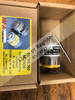
The ultimate 'Green' motor!! I just wonder how you control them! 😮 ▲
⟩⟩
No likes yet
This member will receive 1 point for every like received |
|
💬 Re: Joining the fuselage.
5 years ago by 🇭🇺 MouldBuilder (
Vice Admiral)✧ 14 Views · 1 Like
Flag
One of them is perfect. It is a magic motor. According to the Amazon spec. no battery is required. Instant weight saving.😊
▲
⟩⟩
RNinMunich
|
|
💬 Re: Joining the fuselage.
5 years ago by 🇭🇺 MouldBuilder (
Vice Admiral)✧ 13 Views · 0 Likes
Flag
Thanks Doug.😊
▲
⟩⟩
No likes yet
This member will receive 1 point for every like received |
|
💬 Re: Joining the fuselage.
5 years ago by 🇩🇪 RNinMunich (
Fleet Admiral)✧ 14 Views · 1 Like
Flag
Here's a couple on Amazon UK which should do nicely 😊
▲
⟩⟩
MouldBuilder
|


|
💬 Re: Joining the fuselage.
5 years ago by 🇩🇪 RNinMunich (
Fleet Admiral)✧ 14 Views · 1 Like
Flag
"That is one of the things that I hate about some of these motors, the lack of information on them."
Seek and ye shall find Martin😉 ▲
⟩⟩
Martin555
|
|
💬 Re: Joining the fuselage.
5 years ago by 🇩🇪 RNinMunich (
Fleet Admiral)✧ 14 Views · 1 Like
Flag
Hi again Pete,
Check the specs before you order! MFA's 380 version does about 19k revs!!😮 Look for original Mabuchis or Johnsons. They are a bit tamer😉 25mm could be a problem! I think the 380s / 385s are all 27-28mm🤔 Scrape a mil off the inside of your tech rack tube!? OR, go for a 280 size (23.8mm dia😊) such as this from AliExpress- ▲
⟩⟩
Martin555
|

|
💬 Re: Joining the fuselage.
5 years ago by 🇭🇺 MouldBuilder (
Vice Admiral)✧ 15 Views · 2 Likes
Flag
Hi Doug. Just seen your last comment from yesterday.
I have a lot of preparation work to do on the bow and stern end caps before I fit the `wings` on. I have just purchased a Dremel to help with this work. I will practice first before cutting into the model. You know what practice makes. Smaller mistakes.....Maybe.,😀 ▲
⟩⟩
RNinMunich
Martin555
|
|
💬 Re: Joining the fuselage.
5 years ago by 🇬🇧 Martin555 (
Fleet Admiral)✧ 14 Views · 1 Like
Flag
Thank you.
Martin. ▲
⟩⟩
MouldBuilder
|
|
💬 Re: Joining the fuselage.
5 years ago by 🇬🇧 Martin555 (
Fleet Admiral)✧ 13 Views · 0 Likes
Flag
Hi Doug,
That is one of the things that I hate about some of these motors, the lack of information on them. Martin. ▲
⟩⟩
No likes yet
This member will receive 1 point for every like received |
|
💬 Re: Joining the fuselage.
5 years ago by 🇩🇪 RNinMunich (
Fleet Admiral)✧ 13 Views · 0 Likes
Flag
Don't think so Pete. Gearboxes are usually noticeable as 'bolt-ons'.
Cheers, Doug 😎 ▲
⟩⟩
No likes yet
This member will receive 1 point for every like received |
|
Login To
Remove Ads 💬 Re: Joining the fuselage.
5 years ago by 🇭🇺 MouldBuilder (
Vice Admiral)✧ 14 Views · 1 Like
Flag
Thanks Doug. I was looking at geared motors to keep the rpm down but reading what you have to say, the 385`s at 6 volts should be good. Now to see if I can get these at 25mm diameter maximum.😊
▲
⟩⟩
Martin555
|
|
💬 Re: Joining the fuselage.
5 years ago by 🇭🇺 MouldBuilder (
Vice Admiral)✧ 13 Views · 0 Likes
Flag
Perhaps they have gear boxes? Might account for the extra length.
▲
⟩⟩
No likes yet
This member will receive 1 point for every like received |
|
💬 Re: Joining the fuselage.
5 years ago by 🇩🇪 RNinMunich (
Fleet Admiral)✧ 15 Views · 2 Likes
Flag
Hi Peter,
Around 5000 rpm Off Load at 6V, ~10000 at 12V, depending on manufacturer. Doug 
▲
⟩⟩
Martin555
MouldBuilder
|
|
💬 Re: Joining the fuselage.
5 years ago by 🇭🇺 MouldBuilder (
Vice Admiral)✧ 14 Views · 1 Like
Flag
Get well soon Martin.👍
▲
⟩⟩
Martin555
|
|
💬 Re: Joining the fuselage.
5 years ago by 🇩🇪 RNinMunich (
Fleet Admiral)✧ 15 Views · 2 Likes
Flag
They look about 380 size to me, possibly with slightly longer cans?
▲
⟩⟩
Martin555
MouldBuilder
|
|
💬 Re: Joining the fuselage.
5 years ago by 🇬🇧 Martin555 (
Fleet Admiral)✧ 13 Views · 0 Likes
Flag
Hi Peter.
I honestly don't know. They were just two that I had lying around, I have to open up my WTC to try and sort out a small problem so when I do I will see if there is any markings on them. Unfortunately I will not be able to do that for a while as I am having slight health problems at the moment. Martin. ▲
⟩⟩
No likes yet
This member will receive 1 point for every like received |
|
💬 Re: Joining the fuselage.
5 years ago by 🇭🇺 MouldBuilder (
Vice Admiral)✧ 14 Views · 1 Like
Flag
Hi Martin.
What motors have you fitted in your Gato. Thanks. Peter. ▲
⟩⟩
Martin555
|
|
💬 Re: Joining the fuselage.
5 years ago by 🇭🇺 MouldBuilder (
Vice Admiral)✧ 13 Views · 0 Likes
Flag
Thanks Doug. I think I will come up with my own idea to keep cost down. Any idea of 385 motor rpm at 6volts.
Thanks. Pete. ▲
⟩⟩
No likes yet
This member will receive 1 point for every like received |
|
💬 Re: Joining the fuselage.
5 years ago by 🇩🇪 RNinMunich (
Fleet Admiral)✧ 14 Views · 1 Like
Flag
Hi Peter,
My U25 at 107cm is about 8/10 the size of your Gato, but probably heavier as it's hull is made of four planks of carved wood!😮 Anyway she goes just fine using two 385 motors on 6 or 12V driving 3 blade 30mm props. On 12V way too fast of course but it's fun to show up the speed merchants once in a while😁 Re dive plane retraction- Here's two possibilities! This one from the German model Sub tech expert Engel where I got my Akula 2 kit. It comes with a controller. 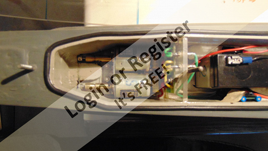
▲
⟩⟩
MouldBuilder
|


|
💬 Re: Joining the fuselage.
5 years ago by 🇭🇺 MouldBuilder (
Vice Admiral)✧ 13 Views · 0 Likes
Flag
As the submarine does not have to move very fast and has two motors driving 35mm propellers, does anybody have a suggestion on how many rpm the shafts need to go. I am sure that torque is more important than rpm but a forward speed of around walking pace should be enough. Your thoughts would be appreciated.
Peter. BTW jb, the bow planes are in the kit, the actuating mechanism is the item I have to figure out. ▲
⟩⟩
No likes yet
This member will receive 1 point for every like received |
|
Login To
Remove Ads 💬 Re: Joining the fuselage.
5 years ago by 🇳🇿 jbkiwi (
Fleet Admiral)✧ 14 Views · 1 Like
Flag
Might I suggest carbon fibre sheet, rod and tube for the bow planes? nice and strong (+ resin coat ) and totally rust free.
▲
⟩⟩
MouldBuilder
|
|
💬 Re: Joining the fuselage.
5 years ago by 🇬🇧 Martin555 (
Fleet Admiral)✧ 15 Views · 2 Likes
Flag
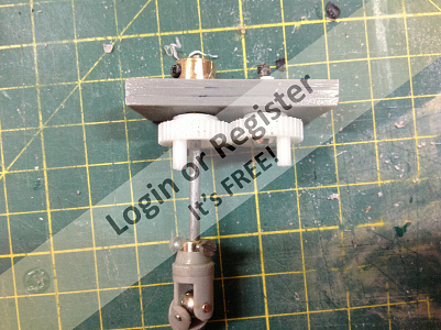
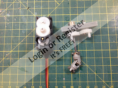
I had a couple of broken servos so I used the main cog from them.
As you need to plan at least three steps ahead. Depending on your WTC and how many channels you will be using and how the bow planes servo is mounted you may find that you might not be able to get the planes to retract. I hope the attached photos will help. Martin. 

▲
⟩⟩
jbkiwi
MouldBuilder
|
📝 Stern Module assembly
5 years ago by 🇭🇺 MouldBuilder ( Vice Admiral)
Vice Admiral)✧ 16 Views · 3 Likes · 4 Comments
Flag
💬 Add Comment
This weekend I decided to do more work on the Gato Submarine. Now I am starting to realise how big this job to build the model is, let alone the WTC which I am thinking about and starting to plan in tandem.
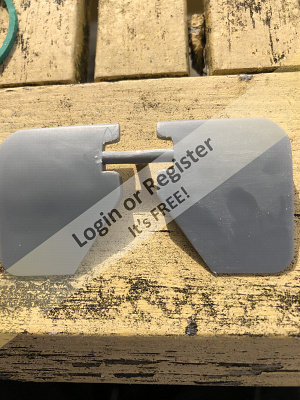
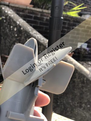
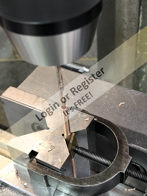
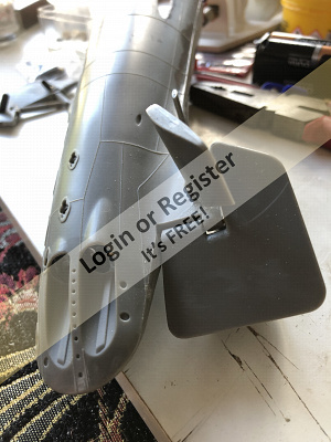
I have been working on the stern module today trying to get the rudder and aft planes in a working state. I have followed the video made by a kind soul on the internet which I am finding very helpful. To make them fit properly has resulted in a lot of filing and reshaping particularly on the rudder. All of the edges were interfering all over. After a considerable amount of adjusting, they now fit and work perfectly. A hole was carefully drilled right through the height of the rudder to allow for a shaft to be inserted for operation. Small holes were also drilled through some waste material to produce two running bearings for the rudder shaft.
There has had to be a considerable amount of material removal inside the stern module halves to allow for the planes and rudder to work. This was done using a burr in the Dremel and files. Great care was taken not to remove too much and go right through the part.
I am having a little problem with warpage of one of the stern halves. You can see the gap between the parts in one of the photographs. It might be that they will glue together without incident if I fix them well with bands during curing. Does anybody have a cunning plan to straighten this part before gluing?
I have purchased the propeller shafts and tubes so further work on this module will continue when they arrive, probably towards the end of July.
I have now purchased my chosen motors. They are MFA 360. I have also ordered the raw materials to make the motor mount and servo trays. I wonder if I have to put the usual three suppressors on the motors if running a 40Mhz transmitter.
Next time I am going to work on the bow planes. I will have them working and retracting. I bought the gears for the retracting mechanism today but have found them to be too big on diameter to fit two side by side in the bow module. The gears are perfect in every other way so I think I will reduce them to quadrants which should fit nicely. More cad design work for me I think.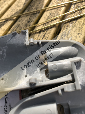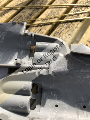
▲
⟩⟩
jbkiwi
Martin555
RNinMunich
|
💬 Re: Stern Module assembly
5 years ago by 🇬🇧 Martin555 (
Fleet Admiral)✧ 14 Views · 1 Like
Flag
Hi Peter,
I had the same and had no problems after it was glued, go for it. I would say good luck but you won't need it.LOL! Martin. ▲
⟩⟩
MouldBuilder
|
|
Login To
Remove Ads 💬 Re: Stern Module assembly
5 years ago by 🇭🇺 MouldBuilder (
Vice Admiral)✧ 14 Views · 1 Like
Flag
Thanks both. I will add suppression next.
As for the warp, I think I will take a chance and glue as is. As the material is probably HIPS, the melt point is very low and I fear further damage could occur if heated. My main fear would be even further warpage as it cools. Better the devil and all that. ▲
⟩⟩
Martin555
|
|
💬 Re: Stern Module assembly
5 years ago by 🇬🇧 Martin555 (
Fleet Admiral)✧ 14 Views · 1 Like
Flag
Hi Peter,
I have found that it will glue together without any problem, you will have to hold it together tightly with masking tape until fully set. Keep up the good work. Martin. ▲
⟩⟩
MouldBuilder
|
|
💬 Re: Stern Module assembly
5 years ago by 🇩🇪 RNinMunich (
Fleet Admiral)✧ 15 Views · 2 Likes
Flag
Hi Pete,
"I have now purchased my chosen motors. They are MFA 360. ... I wonder if I have to put the usual three suppressors on the motors if running a 40Mhz transmitter." Most definitely!! Considering the attenuation of RF signals under water the last thing you want to do is take risks with interference😮 As the RF signal level falls off when you dive the boat any local interference, i.e. from the motors, will become more significant at the RX input. Re warped stern parts. You could try gently (and I mean gently Bentley!) warming the part (hair dryer?) while weighting it down on a flat surface. You may want to put some shaped wood block supports inside to ensure the part does not bend inwards. Cheers, Doug 😎 ▲
⟩⟩
MouldBuilder
Martin555
|
📝 WTC construction.
5 years ago by 🇭🇺 MouldBuilder ( Vice Admiral)
Vice Admiral)✧ 15 Views · 2 Likes · 3 Comments
Flag
💬 Add Comment
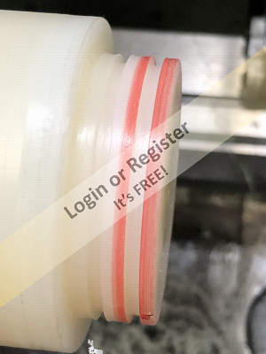
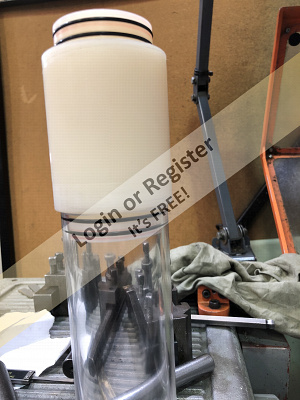
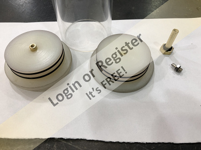
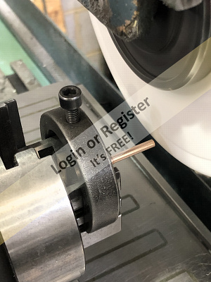
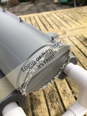
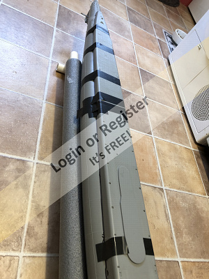
I have started work on the Water Tight Compartment this weekend. I have started by turning the end caps for the internal ballast tank and then made two end caps for the 70mm diameter by 2mm wall section main WTC tube. The internal ballast tube is 60mm diameter with a 4mm wall section in case I want to pressurise it. I have yet to determine the exact ballast system I will use. I am trying to cover all bases so that I can make this final decision later.
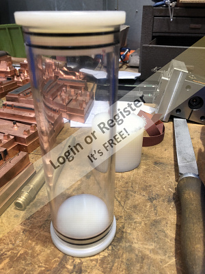
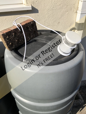
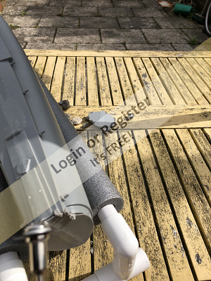
I have now assembled the ballast unit and all looks good. I have made a test tube about 80mm long to test the main WTC tube and caps. I had a little trouble keeping the o rings in place as the thinner wall tube has distorted slightly and is oval. I filed a chamfer at each end of the tube to help the rings squeeze nicely. This improved the situation and all was looking good,
Earlier today I tied the test WTS to a brick with both end caps in place to check for leaks. I then lowered it to the bottom of a water butt and filled it with water. The unit was left there for 90 minutes. On removal I was pleased to see that there were no leaks. The depth was around 50cm.
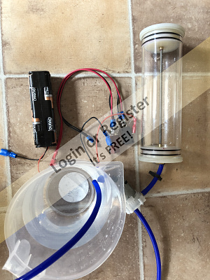
I have now decided to ballast the submarine in one of two ways. The first is to have a reversible water pump and a motorised valve. The pump would both fill and empty the tank with the valve opening and closing the entry pipe. The air inside the chamber would be pressurised so my concern would be the capability of the pump to have enough power to overcome the back pressure created by the air compression. The second possibility would be to have the pump fill a bladder inside of the ballast tube. This would mean that the inner tube need not be water or air tight so the air would not be compressed in the same way so the pump would not need to be so powerful.
The pictures show the production of the end caps and the assembled unit. The test tank is also shown. The ballast tube with the end caps fitted inside the WTC tube is also pictured.
The prop shafts have been delayed by 8 weeks in Hong Kong even though they said they had sent them to me on 12th June. Royal Mail informed me that they were finally sent on 23rd August. I can continue with the main model build on their arrival. This is important so that I can establish exactly how much room I have for the WTC.


I have now assembled the ballast unit and all looks good. I have made a test tube about 80mm long to test the main WTC tube and caps. I had a little trouble keeping the o rings in place as the thinner wall tube has distorted slightly and is oval. I filed a chamfer at each end of the tube to help the rings squeeze nicely. This improved the situation and all was looking good,
Earlier today I tied the test WTS to a brick with both end caps in place to check for leaks. I then lowered it to the bottom of a water butt and filled it with water. The unit was left there for 90 minutes. On removal I was pleased to see that there were no leaks. The depth was around 50cm.
I have now decided to ballast the submarine in one of two ways. The first is to have a reversible water pump and a motorised valve. The pump would both fill and empty the tank with the valve opening and closing the entry pipe. The air inside the chamber would be pressurised so my concern would be the capability of the pump to have enough power to overcome the back pressure created by the air compression. The second possibility would be to have the pump fill a bladder inside of the ballast tube. This would mean that the inner tube need not be water or air tight so the air would not be compressed in the same way so the pump would not need to be so powerful.
The pictures show the production of the end caps and the assembled unit. The test tank is also shown. The ballast tube with the end caps fitted inside the WTC tube is also pictured.
The prop shafts have been delayed by 8 weeks in Hong Kong even though they said they had sent them to me on 12th June. Royal Mail informed me that they were finally sent on 23rd August. I can continue with the main model build on their arrival. This is important so that I can establish exactly how much room I have for the WTC.
▲
⟩⟩
Martin555
jbkiwi
|
💬 Re: WTC construction.
5 years ago by 🇬🇧 Martin555 (
Fleet Admiral)✧ 14 Views · 1 Like
Flag
Hi Peter,
That all sounds great and I hope it all works out. It will be the simplest of things that catches you out. Like the wires will pass through but the connector on the end won't. The radius of the tube prevents you from fitting the bits where You wanted to fit them. I spent more time working out everything before actually making it, and I thought I had it all sorted out, but when it actually came time to make it that is when the problems started. These are complex in there construction so I tried to keep it as simple as I possibly could. Good luck, Looking forward to your future posts. Martin555. ▲
⟩⟩
MouldBuilder
|
|
Login To
Remove Ads 💬 Re: WTC construction.
5 years ago by 🇭🇺 MouldBuilder (
Vice Admiral)✧ 14 Views · 1 Like
Flag
Hi Martin.
I have a 3mm gap all around the tube. I have not thought as far as the connection between the forward and rear planes yet. I will stumble over that one later. I am still considering having a tube through the centre or near the top for wiring. I will see how it pans out. (Wish this spell checker used proper English and not US English). The inner tube is a nice slide fit inside the WTC. My plan is to get the servo, battery and motor frames to hold it in place. The length is only a guess at this stage and if only a small amount of water is needed to submerge the submarine, then I will probably shorten it. I have used 4mm wall section tube for the ballast tank and I am going to tie rod the caps in place using brass bolts with SS threaded rod between. I will modify the bolts with M4 internal threads and o rings under the heads. Should work a treat....I hope.😊 ▲
⟩⟩
Martin555
|
|
💬 Re: WTC construction.
5 years ago by 🇬🇧 Martin555 (
Fleet Admiral)✧ 14 Views · 1 Like
Flag
Hi Peter,
You have done an excellent job on your WTC so far, well done. I wish I had the equipment and materials to do the same. Like you I had to do a lot of forward planning before making my WTC. Having a water tight tube inside a water tight tube is a good idea as it reduces the risk of leaks. But have you enough room between the inner and outer tube to pass wiring through ? I am assuming that the forward and aft bow planes will have separate servos operating via a Y connector. Or are they being operated separately. How are you going to hold the inner tube in place.? The centre section on my WTC is a separate tank with a through tube to enable my wiring to pass through (you have probably seen my thread on here) I think I also mentioned that you will not need to pump in much water to get the Gato to submerge. And after experimenting I decided to fit a party balloon to also prevent leeks around the wiring through tube. I ended up venting the air as I had pressure problems. Martin555. ▲
⟩⟩
MouldBuilder
|
📝 The ballast unit prototype.
5 years ago by 🇭🇺 MouldBuilder ( Vice Admiral)
Vice Admiral)✧ 16 Views · 3 Likes · 1 Comment
Flag
💬 Add Comment
Just a small update today.
I have just completed the test ballast unit. The end caps are held in with fabricated bolts so I do not expect problems here. I do, however, expect problems with pipes blowing off due to the pressure I am going to create in the tube when water is pumped in. I will order some clips to try to solve this potential problem. I expect them to arrive during next week. Tests will begin next weekend. Just enough time to purchase water proofs and an umbrella.😊


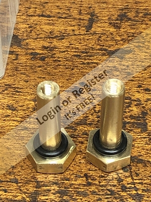

I have just completed the test ballast unit. The end caps are held in with fabricated bolts so I do not expect problems here. I do, however, expect problems with pipes blowing off due to the pressure I am going to create in the tube when water is pumped in. I will order some clips to try to solve this potential problem. I expect them to arrive during next week. Tests will begin next weekend. Just enough time to purchase water proofs and an umbrella.😊
▲
⟩⟩
mturpin013
Martin555
RNinMunich
|
💬 Re: The ballast unit prototype.
5 years ago by 🇬🇧 Martin555 (
Fleet Admiral)✧ 14 Views · 1 Like
Flag
Keep up the good work.
Martin555. ▲
⟩⟩
MouldBuilder
|
📝 Stern Section
5 years ago by 🇭🇺 MouldBuilder ( Vice Admiral)
Vice Admiral)✧ 14 Views · 1 Like · 2 Comments
Flag
💬 Add Comment
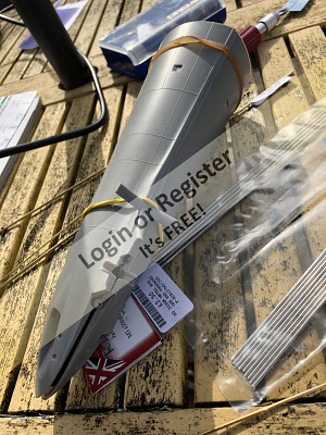
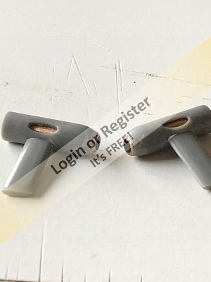
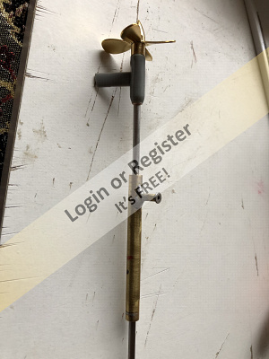
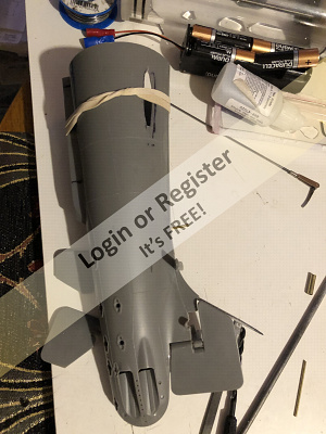
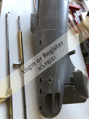
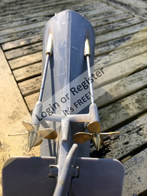
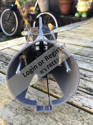
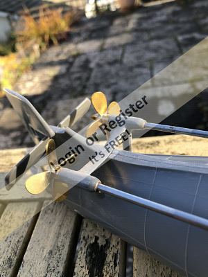
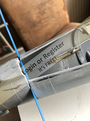
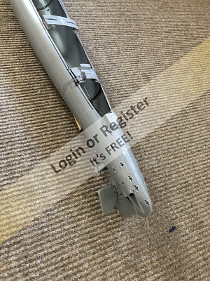
The prop shafts and propellers arrived which now gives me a lot of things I can do to forward the build. I decided that the best way forwards was to complete the rear section, which includes the stern planes and the rudder and their operating system. The hardest part here was to mark out the cuts ion the hull halves accurately. I then used a Dremel to remove the excess material and loosely fit the shafts. As the tubes are not long enough to reach the rear bearings and skegs, I have had to turn, drill and fit some phosphor bronze bushes to act as rear shaft bearings. I hope that vibration when turning does not pull the parts off of the main hull. After this, I fitted the stern plane and rudder to check for function. There was a little resistance so I removed more material from both halves until free movement was achieved. I then turned my attention to the actuating mechanisms which would be connected to the servo rods. I had an old servo arm so I drilled part way through to a flat bottom, turned a wheel collet down and press fitted it in. The picture shows the completed arm. I will remove the excess arms when fitting them. This controls the rudder. For the stern plane, I heated up a rod of 2mm steel and flattened it to about 3mm wide. I then drilled a hole in the end to fit an aeroplane elevator/flaps connector as pictured. The next thing I will do is to assemble all of the parts and glue the two halves together. This is a job for next week. I want to do a ballast tank test this weekend.


▲
⟩⟩
Martin555
|
💬 Re: Stern Section
5 years ago by 🇩🇪 RNinMunich (
Fleet Admiral)✧ 15 Views · 2 Likes
Flag
"As the tubes are not long enough to reach the rear bearings and skegs, "
They are not supposed to be Peter! The stuffing tube box stops at the hull exit, so what you are doing is correct to the originals👍 Doug 😎 ▲
⟩⟩
MouldBuilder
Martin555
|
|
💬 Re: Stern Section
5 years ago by 🇬🇧 Martin555 (
Fleet Admiral)✧ 13 Views · 0 Likes
Flag
Nice work Peter, keep it up.
Martin555. ▲
⟩⟩
No likes yet
This member will receive 1 point for every like received |
📝 Gato Ballast Tank Test
5 years ago by 🇭🇺 MouldBuilder ( Vice Admiral)
Vice Admiral)✧ 36 Views · 1 Like · 30 Comments
Flag
💬 Add Comment
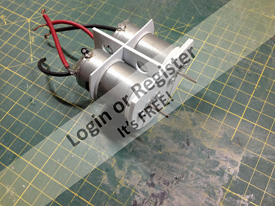
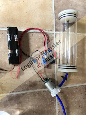
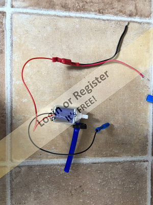
Well, I have finally taken delivery of all of the parts for testing my ballast idea. I used Martin`s idea for operating the reversing action of the pump which will eventually be operated by a small servo. This uses two micro switches wired such that the pump will operate in opposite directions dependent on which switch was activated. I have included a picture of his wiring arrangement. If you press one switch, the cylinder is filled. Press the other, and it pumps the water out. I have a solenoid valve to shut the water supply pipe down as soon as the pump is switched off. The problem I have though is how to wire up this valve so that each microswitch operation opens it. If I wire the solenoid up using the common on both switches it is in short circuit. I need the positive of the valve always to be positive. With this switch arrangement, the common terminal alternates between positive and negative. How do I wire it Doug!! The water leaks out through the pump without it.
Putting this problem aside though, the system worked perfectly. The pump managed to fill the tube about 60% before labouring. I think this will be more than enough to submerge the Submarine. What do you think Martin?
Hopefully one of you electronics guys can give me a simple solution to my solenoid valve problem. Next job is to make the assembly much smaller.
I have done a small video of the test which I hope to upload.
▲
⟩⟩
Martin555
|
💬 Re: Gato Ballast Tank Test
5 years ago by 🇭🇺 MouldBuilder (
Vice Admiral)✧ 37 Views · 1 Like
Flag
Thanks Doug.
Following several tests I have carried out, the valves are strong enough for the job but only if the flow direction is correct. I did consider that the pressure was causing the problem but discounted this when I found that I can fill in stages and the valve closes each time. It will not, however, open when the pump is reversed. It does energise and throw the valve when the circuit is activated with no water present. My latest plan is to use the forward and reverse functions of the pump with each circuit protected with a one way valve and a separate solenoid valve for each direction. To make this work, I will have to ensure that the input valve only works in forward and the output valve in reverse only. To do this I will need a small circuit to split the load. I have most common components here but no brain for designing the required circuit. I will enjoy building it though. With the valve plumbed the right way, I filled the tank in stages to 80% full and held it for 1 1/2 hours, mainly as I could not pump it out. I had to remove the input pipe to empty. It was holding a decent pressure. I will not fill it this much again for safety and I will make a simple safety valve. I got my 4 year old grand child to draw a scheme of my latest plan with the wires for the valves waiting for a circuit. I will ask him to improve his drawings for any future attempts.😁 For reference, the flow does go in the side connection. I just checked your comment on polarity. You are right, they work either way around. Ooooooppppssss!!! Oh, nearly forgot; I have been advised that if I use crawler mode on the ESC, the output voltage is the same in both directions. 
▲
⟩⟩
mturpin013
|
|
Login To
Remove Ads 💬 Re: Gato Ballast Tank Test
5 years ago by 🇩🇪 RNinMunich (
Fleet Admiral)✧ 37 Views · 2 Likes
Flag
Hi Pete,
Thanks for your PM. I'll get back to you on that. Some thoughts! (Doh my 'ead 'urts🤕) The Solenoid Valve. Suspect number 1! 1 Tested a few of my solenoids and electro magnets from a batch picked up for a song at a local flea market. (Felt a bit of a twit doin' a song and dance routine in the middle of the market🤔, but it worked😁) Sooo, the solenoid doesn't care about the polarity of the supply volts, as was already beginning to dawn on me. As soon as the current flows in the coil (either way) the magnetic field is there and drags the core in on mine. 2 I note that your valve has input and output at right angles Pete.Which end is the tank connected to? If, as I suspect, it is connected to the side tube it may be that the back pressure from the tank is jamming the valve against the opposite side. That, combined with probable reduced voltage from the ESC in reverse (Suspect number 2!) AND the 1.4V drop of the bridge rectifier (2x0.7V of the diodes, Suspect number 3) means the solenoid coil is not getting enough current to create a strong enough field to overcome the friction of the side pressure. Solution? 1 Pt 1 tells us we can dispense with the rectifier. 2 Then connect the tank to the pipe which is in line with the solenoid, thus eliminating the side pressure on the valve plunger. If back pressure from the tank then causes the valve to open / weep then the valve return springs are not man enough for the job. 😭 As mentioned above, it could also be that you pumped in more water than you actually need, thus creating unnecessarily high pressure in the tank. That's what I meant about unrealistic test conditions. You might be chasing a Ghost Pete 😮 3 Check ESC programming possibilities to see if the reverse voltage can be increased, to 100% if possible. 4 Most transmitters these days have a 'servo travel' function, up to 150% independently at both ends. Maybe (if available on your TX Pete) that could be used to increase the reverse voltage when applied to the ESC channel? If nun o that woiks then, as Grandad (a master carpenter and cabinet maker) liked to say- "If all else fails .... use bloody great nails!" 😁 And Change valve! I'll PM or mail you on the two valve version Pete. G'night all, Doug 😎😴💤💤 ▲
⟩⟩
MouldBuilder
Martin555
|
|
💬 Re: Gato Ballast Tank Test
5 years ago by 🇬🇧 Martin555 (
Fleet Admiral)✧ 37 Views · 2 Likes
Flag
I agree with Doug regarding testing.
I think that by the time your WTC is complete it will be heavier than mine, Therefore you would need less water ballast. My WTC weighs 4 3/4 Lbs.( no extra weight added) When I placed my WTC in Big Blue it floated and the water level Was just above the centre. I attached some lead underneath just to level it up. Then pumped in about 3/4 of a cup of water she then submerged to the bottom. When I first placed the WTC in slowly it look as if it was going to sink, so I was quite happy when it stayed afloat. I don't know if this helps. Martin555. ▲
⟩⟩
RNinMunich
MouldBuilder
|
|
💬 Re: Gato Ballast Tank Test
5 years ago by 🇭🇺 MouldBuilder (
Vice Admiral)✧ 36 Views · 0 Likes
Flag
I agree Doug. Problem is that I cannot, so far, find a valve that is not too large and have relatively small connections. (tube connectors)😐
▲
⟩⟩
No likes yet
This member will receive 1 point for every like received |
|
💬 Re: Gato Ballast Tank Test
5 years ago by 🇩🇪 RNinMunich (
Fleet Admiral)✧ 37 Views · 2 Likes
Flag
Hi Pete,
Where as I tend to agree that you need a solenoid with more shove, and above all stronger return springs, I don't think that your test set up is properly simulating the operating conditions. With your test set up there will never be more than ambient air pressure on the input side of the valve. Whereas under operating conditions in the wet stuff the pressure on the input will rise as the boat goes deeper. This will help counteract the back pressure from the tank. Also I don't think you will need to fill the tank so full and thus create such back pressure. A truer test would be an immersion test with some weight hung on the tank to simulate the projected all up weight of the sub. In this respect Martin's test in Big Blue was much closer to reality. Once properly trimmed on the surface 'any' additional weight will start sending the boat down. I'd be surprised if you need more than about +10% to submerge. Don't know the trimmed displacement of the boat or the capacity of your tank so can't be more precise. Cheers, Doug 😎 PS I also think you'd be better off spending few bob more on a decent brass valve instead of cheap plastic. False economy, saving in the wrong place Pete!!😉 ▲
⟩⟩
Martin555
MouldBuilder
|
|
💬 Re: Gato Ballast Tank Test
5 years ago by 🇭🇺 MouldBuilder (
Vice Admiral)✧ 36 Views · 0 Likes
Flag
I have done further tests on the system. Everything is working well once. Then it all goes wrong. The pump will not prime to refill. I am sure that the solenoid valve is not up to the task. It is being pushed open when the pressure is direct onto the piston and jams when the pressure is adjacent. I need a much stronger solenoid and one which blocks across the flow. I will have to see what I can find. Still interested in our fundamental test error though Doug.🤔
▲
⟩⟩
No likes yet
This member will receive 1 point for every like received |
|
💬 Re: Gato Ballast Tank Test
5 years ago by 🇭🇺 MouldBuilder (
Vice Admiral)✧ 36 Views · 0 Likes
Flag
What did we miss Doug.
▲
⟩⟩
No likes yet
This member will receive 1 point for every like received |
|
💬 Re: Gato Ballast Tank Test
5 years ago by 🇩🇪 RNinMunich (
Fleet Admiral)✧ 37 Views · 2 Likes
Flag
Theoretically it might be possible to burn out the coil, but usually only if excessive voltage applied.
BTW: I looked again at your tank test and I think we've all been making a fundamental error! Namely ignoring the test conditions! More tomorrow, I'm bushed so G'night, Doug 😎 ▲
⟩⟩
Martin555
MouldBuilder
|
|
💬 Re: Gato Ballast Tank Test
5 years ago by 🇭🇺 MouldBuilder (
Vice Admiral)✧ 36 Views · 1 Like
Flag
Doug,
I think I have a solution to the valve problem. It depends on your answer to this question. Am I right in saying that if a solenoid does not throw and the power is still applied, no damage is done as it is only an electro magnet. Thanks. ▲
⟩⟩
Martin555
|
|
💬 Re: Gato Ballast Tank Test
5 years ago by 🇩🇪 RNinMunich (
Fleet Admiral)✧ 37 Views · 2 Likes
Flag
I reckon we three must be cousins! 😎
▲
⟩⟩
MouldBuilder
Martin555
|
|
💬 Re: Gato Ballast Tank Test
5 years ago by 🇬🇧 Martin555 (
Fleet Admiral)✧ 37 Views · 2 Likes
Flag
"I want to but my brain and hands do something else."
I know exactly what you mean, I suffer with that quite a bit too. Martin555. ▲
⟩⟩
MouldBuilder
RNinMunich
|
|
Login To
Remove Ads 💬 Re: Gato Ballast Tank Test
5 years ago by 🇭🇺 MouldBuilder (
Vice Admiral)✧ 36 Views · 1 Like
Flag
Sorry Martin. Keeping things simple does not compute. I am afraid my brain will not allow. I want to but my brain and hands do something else. I must have a strange genetic flaw. I must find a way around this. I know what you mean and agree, but those gremlins will win in the end.😁
▲
⟩⟩
Martin555
|
|
💬 Re: Gato Ballast Tank Test
5 years ago by 🇬🇧 Martin555 (
Fleet Admiral)✧ 37 Views · 2 Likes
Flag
Although I like your idea for your WTC ballast I think in my own personal opinion is that there is no need to over complicate the system.
Making a simple bladder system is tricky enough. If the Gato that you are making was much bigger then yes a better system would be ideal. Maybe it's me but I think you should keep it as simple as possible. Martin555. ▲
⟩⟩
MouldBuilder
RNinMunich
|
|
💬 Re: Gato Ballast Tank Test
5 years ago by 🇩🇪 RNinMunich (
Fleet Admiral)✧ 37 Views · 2 Likes
Flag
Mornin' Peter,
Can you post / mail me the valve instructions please. Hopefully there is a sectional diagram included. "The reason I was trying to avoid the piston system was to avoid the out of balance nose or tail first dive." If the boat is properly trimmed at the surface in the first place with the tank correctly positioned there is no reason why it should dive tail first! Real subs don't usually static dive (or surface) anyway. Always underway with a few degrees down / up plane to assist. Trick when diving is to switch to level planes (a little UP plane at the stern) at the right time to level off at the required depth! There are some neat auto trim / depth holding modules around to help with that😉 (Another reason for going digital servos!) Cheers, Doug 😎 
▲
⟩⟩
MouldBuilder
Martin555
|
|
💬 Re: Gato Ballast Tank Test
5 years ago by 🇭🇺 MouldBuilder (
Vice Admiral)✧ 36 Views · 2 Likes
Flag
Hi Doug.
I was thinking exactly as you. The pressure vessel I have made is of 4mm section at 52mm i.d. I have a sealed bolted rod holding the caps is place. The caps are 24mm thick Nylon 6. The pipe connector is M5 with a 2.2mm hole. Not much pressure area here. I think I might continue but taking extra care. I did further tests yesterday and found that the solenoid valve works perfectly when not connected to the pump and under pressure in both directions. The problem is the valve. Do you think I need a more powerful one or do you think the valve only works in one flow direction. For some reason the instructions show a direction of flow but as the valve only blocks the through hole, I cannot see why. The reason I was trying to avoid the piston system was to avoid the out of balance nose or tail first dive.😊 ▲
⟩⟩
RNinMunich
Martin555
|
|
💬 Re: Gato Ballast Tank Test
5 years ago by 🇩🇪 RNinMunich (
Fleet Admiral)✧ 37 Views · 2 Likes
Flag
Hi Peter,
whereas I find that perhaps a little exaggerated if the materials used are robust enough, and I don't really think the pressures generated will be that great. However, I have to admit that I found the whole thing a little suspect, from the functionality point of view, right from the get go. So I kept out of the constructional side to see where it went😉 I have a piston tank system for my Akula. Does this mean I can cancel my pump / solenoid control experiments? 🤔 Cheers, Doug 😎 BTW; If you put a bladder in the same construction it won't make a ha'p'orth of difference to the internal pressures generated! ▲
⟩⟩
Martin555
MouldBuilder
|
|
💬 Re: Gato Ballast Tank Test
5 years ago by 🇭🇺 MouldBuilder (
Vice Admiral)✧ 36 Views · 1 Like
Flag
I have been advised to stop with this method of a ballast tank. A veteran at this subject has advised that I am making a potential bomb which could injure somebody if it decided to go. He said that a simple fracture around my pipe connections could send parts flying causing potential injury. Now that it has been pointed out I see what he means. Back to the drawing board and a bladder system I think.🤔
▲
⟩⟩
Martin555
|
|
💬 Re: Gato Ballast Tank Test
5 years ago by 🇩🇪 RNinMunich (
Fleet Admiral)✧ 36 Views · 1 Like
Flag
Absolutely Martin👍
Also the solenoid will not much like the pulsed voltage from an ESC. Especially if the 'On Time' is reduced when the ESC is in 'Reverse', as Pete suspects. To operate they depend on a steady DC voltage to maintain a constant magnetic field. After all, a solenoid is nothing more than an electromagnet with one part moveable! Apply an AC or pulsed voltage and it will try to chunter back and forth at the frequency of the AC voltage or the Pulse Repetition Rate 🤔 Go for the microswitches and a relay Pete👍 Cheers, Doug😎 ▲
⟩⟩
Martin555
|
|
💬 Re: Gato Ballast Tank Test
5 years ago by 🇬🇧 Martin555 (
Fleet Admiral)✧ 37 Views · 2 Likes
Flag
Hi Peter,
You can do that just by using the pumps on/off switch. To make it dive or surface slower switch the pump on and off in stages. Martin555. ▲
⟩⟩
RNinMunich
MouldBuilder
|
|
💬 Re: Gato Ballast Tank Test
5 years ago by 🇭🇺 MouldBuilder (
Vice Admiral)✧ 36 Views · 1 Like
Flag
So that I have full control of the dive. I like to vary the time it takes to submerge. Very realistic.
▲
⟩⟩
Martin555
|
|
💬 Re: Gato Ballast Tank Test
5 years ago by 🇬🇧 Martin555 (
Fleet Admiral)✧ 37 Views · 1 Like
Flag
Hi Peter,
I am sorry but I am struggling to get my head around this. Can you explain to me why you want to adjust the flow speed of the pump. Martin555. ▲
⟩⟩
MouldBuilder
|
|
Login To
Remove Ads 💬 Re: Gato Ballast Tank Test
5 years ago by 🇭🇺 MouldBuilder (
Vice Admiral)✧ 36 Views · 2 Likes
Flag
Don`t forget, it probably won`t take any where near 80% fill to submerge some way down under the water.
▲
⟩⟩
RNinMunich
Martin555
|
|
💬 Re: Gato Ballast Tank Test
5 years ago by 🇬🇧 Martin555 (
Fleet Admiral)✧ 37 Views · 2 Likes
Flag
If I am not mistaken the real submarine would take between 30-60 seconds to get decks awash, so for the scale of your model 40 seconds would be about right.
At speed with plains set it might reduce the dive time a bit making it quicker to submerge. So really you should not need to control the flow rate. Just had another thought. If that took 40 seconds to fill the tank at full speed then you will require a second pump connected. By connecting the two pumps to a two stage switch setup you could start filling with one pump then to fill quicker the second pump will kick in. The same for emptying. Martin555. ▲
⟩⟩
RNinMunich
MouldBuilder
|
|
💬 Re: Gato Ballast Tank Test
5 years ago by 🇭🇺 MouldBuilder (
Vice Admiral)✧ 36 Views · 1 Like
Flag
I like your switch idea but I would like to control the flow rate of the pump. I can fill the cylinder to 80% in about 40 seconds. I would like to make this variable. Hence the speed controller.😊
▲
⟩⟩
Martin555
|
|
💬 Re: Gato Ballast Tank Test
5 years ago by 🇬🇧 Martin555 (
Fleet Admiral)✧ 37 Views · 2 Likes
Flag
I think that the three switch method I suggested earlier is the simplest way.
Martin555. ▲
⟩⟩
MouldBuilder
RNinMunich
|
|
💬 Re: Gato Ballast Tank Test
5 years ago by 🇭🇺 MouldBuilder (
Vice Admiral)✧ 36 Views · 1 Like
Flag
I am continuing to have a problem with this set up. Almost. I have substituted the micro switches for a 60A speed controller. I connected up the solenoid valve and it only opens on the filling cycle. It will not activate when trying to empty it by using reverse. I then fitted a bridge rectifier in parallel between the pump and the power supply. Again it works in forward but not reverse. I tried the valve on its own and it worked perfectly through the bridge rectifier with whichever polarity I had it connected to. I cannot figure out why it will not activate in reverse. While writing this I think I have just thought why it won`t work in reverse. If I am not mistaken, the Hobbyking 860 dual halves the output in reverse. Probably not enough power to activate the solenoid valve. Can anybody think of a simple way around this. I could get a speed controller that does not reduce power in reverse but I would like to try to get around it another way.
Thanks.😊 ▲
⟩⟩
Martin555
|
|
💬 Re: Gato Ballast Tank Test
5 years ago by 🇬🇧 Martin555 (
Fleet Admiral)✧ 36 Views · 0 Likes
Flag
Excellent Graham,
I like the diode bridge rectifier idea. Martin555. ▲
⟩⟩
No likes yet
This member will receive 1 point for every like received |
|
💬 Re: Gato Ballast Tank Test
5 years ago by 🇭🇺 MouldBuilder (
Vice Admiral)✧ 36 Views · 1 Like
Flag
Thanks Martin and Graham.
A super mechanical idea Martin, That would work well. I thought some arrangement of diodes would do the job Graham but never thought of a bridge rectifier. As both pump and solenoid work on 12 volts and that I have a bridge rectifier, I will try that first. Thanks to you both as they are both great ideas.👍 ▲
⟩⟩
Martin555
|
|
💬 Re: Gato Ballast Tank Test
5 years ago by 🇬🇧 Graham93 (
Vice Admiral)✧ 37 Views · 2 Likes
Flag
Two more ways to control the valve.
If the valve is the same voltage as the pump, then a bridge rectifier as shown in the diagram on the left will keep the polarity of the supply to the valve constant. As an alternative, especially if you had a valve of different voltage, then a relay wired as shown in the diagram on the right will also work. 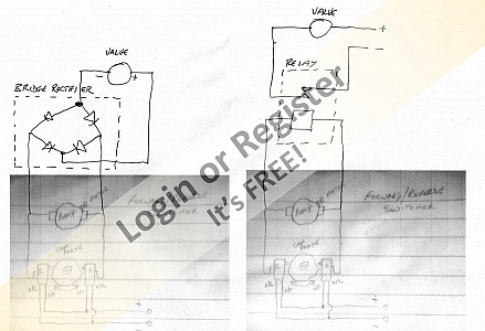
▲
⟩⟩
Martin555
MouldBuilder
|
|
💬 Re: Gato Ballast Tank Test
5 years ago by 🇬🇧 Martin555 (
Fleet Admiral)✧ 37 Views · 1 Like
Flag
Hi Peter,
I am assuming that you will be using the small servos if so your tube will be lighter than mine to start off with. My ballast tank has an internal dissension of 120 mm in length I think that yours is larger so will have more weight of water. Re: valve The only way I know of at the moment is if you have a third micro switch attached to the same cam with just enough cut out so that in the middle position the valve will be open and ether side will activate the valve. Run negative wire directly to the valve and positive to the switch common then from the switch to the valve. I hope that makes sense. Doug would explain this better than me or he will know a better way. Nice job well done. Martin555. 
▲
⟩⟩
MouldBuilder
|
📝 Lightening the hull
5 years ago by 🇭🇺 MouldBuilder ( Vice Admiral)
Vice Admiral)✧ 36 Views · 4 Likes · 6 Comments
Flag
💬 Add Comment
I have decided to leave the ballast system for now. I am confident that my pressurised system will work very well but I have to source a much stronger solenoid valve. Ideas on this would be welcome but weight must be a consideration along with the tube connection size.
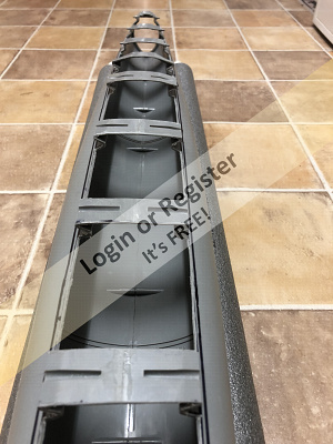
I have turned my attention to the main build. My aim for this session was to complete the aft section and cut all of the weight reducing sections. The first job was to place all of the decking parts and forward and aft sections into place using tape and mark all around with a marker pen. The parts were removed and another line drawn about 6mm (1/4”) inside. This is so that any removed material will not be visible once the deck is fixed back into position. Lines were then drawn about 12mm (1/2”) each side of the hull half connection points and the large areas cross hatched to avoid mistakes.
Time for the Dremel. I fitted the Dremel with a 25mm (1”) diameter 0.8mm (1/32”) rotary saw blade and very carefully cut all of the sections out. To join all of the cuts together, I used a 300mm (12”) hacksaw blade. Great care had to be taken with this process not only to avoid a visible cut, but also not to remove a finger. Regular counts were taken on fingers just in case.
To complete this task. I carefully removed all of the plastic burrs with a needle file. These are quite severe with Styrene but relatively easy to remove. I was happy with the results of this cutting.
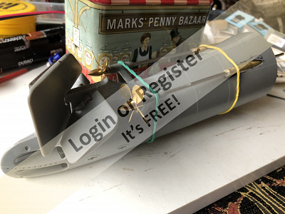
The next item I addressed was the aft section. I had to try to assemble the two halves whilst installing the rudder, aft planes and their operating rods and connectors at the same time. I had previously made the connector rods and had carried out successful trials whilst holding the parts together with elastic bands. The time had arrived to glue the halves together with all of the parts in place. I assembled all of the parts again with bands and started to glue a part at a time. Disaster. I broke the aft planes in half. I was trying to be clever and keep this part in its original supplied condition and ignored previous builds that had strengthened this part. Not a good idea. I now have to try to repair this part and put in place even though both halves are now glued together. This is a job for the next update.
Just a reminder, if anybody knows of a solenoid valve that fits the requirements, help would be greatly appreciated.
Thanks for reading. Peter.😊


I have turned my attention to the main build. My aim for this session was to complete the aft section and cut all of the weight reducing sections. The first job was to place all of the decking parts and forward and aft sections into place using tape and mark all around with a marker pen. The parts were removed and another line drawn about 6mm (1/4”) inside. This is so that any removed material will not be visible once the deck is fixed back into position. Lines were then drawn about 12mm (1/2”) each side of the hull half connection points and the large areas cross hatched to avoid mistakes.
Time for the Dremel. I fitted the Dremel with a 25mm (1”) diameter 0.8mm (1/32”) rotary saw blade and very carefully cut all of the sections out. To join all of the cuts together, I used a 300mm (12”) hacksaw blade. Great care had to be taken with this process not only to avoid a visible cut, but also not to remove a finger. Regular counts were taken on fingers just in case.
To complete this task. I carefully removed all of the plastic burrs with a needle file. These are quite severe with Styrene but relatively easy to remove. I was happy with the results of this cutting.
The next item I addressed was the aft section. I had to try to assemble the two halves whilst installing the rudder, aft planes and their operating rods and connectors at the same time. I had previously made the connector rods and had carried out successful trials whilst holding the parts together with elastic bands. The time had arrived to glue the halves together with all of the parts in place. I assembled all of the parts again with bands and started to glue a part at a time. Disaster. I broke the aft planes in half. I was trying to be clever and keep this part in its original supplied condition and ignored previous builds that had strengthened this part. Not a good idea. I now have to try to repair this part and put in place even though both halves are now glued together. This is a job for the next update.
Just a reminder, if anybody knows of a solenoid valve that fits the requirements, help would be greatly appreciated.
Thanks for reading. Peter.😊
▲
⟩⟩
RNinMunich
jbkiwi
Graham93
Martin555
|
💬 Re: Lightening the hull
5 years ago by 🇭🇺 MouldBuilder (
Vice Admiral)✧ 36 Views · 1 Like
Flag
We think alike Martin. I was going to write to Bob. You nudged me in to doing it.
Thanks. Peter.😊 ▲
⟩⟩
Martin555
|
|
Login To
Remove Ads 💬 Re: Lightening the hull
5 years ago by 🇬🇧 Martin555 (
Fleet Admiral)✧ 37 Views · 1 Like
Flag
If you look at Bob Martin's web site (the nautilus drydocks) they use solenoid valves on there submarine systems.
Or maybe send him an email explaining your problem and he might have a solution. Martin555. ▲
⟩⟩
MouldBuilder
|
|
💬 Re: Lightening the hull
5 years ago by 🇭🇺 MouldBuilder (
Vice Admiral)✧ 36 Views · 2 Likes
Flag
Thanks Doug. Lots for me to ponder over.
Going back to the solenoid valve, I am learning that it is extremely difficult, if not impossible, to find one that can flow in both directions.🤔 ▲
⟩⟩
RNinMunich
Martin555
|
|
💬 Re: Lightening the hull
5 years ago by 🇩🇪 RNinMunich (
Fleet Admiral)✧ 37 Views · 2 Likes
Flag
Hi Pete,
I would be tempted to make new stronger planes from brass sheet anyway. Your "remaining plastic pegs" are going to be pretty weak and vulnerable!! On my Type 1A U-25 the planes are brass sheet connected by a 3mm brass rod. The rod is slotted at the ends to fit over the planes to enable a good strong solder joint with little chance of snapping under load or if you hit something!😮 Short lengths of 3mm I/D brass tube were epoxied into the hull to act as bearers. A control arm was made from 1mm brass sheet, with a 3mm hole at one end for soldering to the rod, and a 1mm hole at the other for connecting the operating Bowden cable using a clevis, aircraft style😉 With this type of wooden sandwich hull construction it is virtually impossible to do this for the stern planes, so only the bow planes are controllable. The construction of the stern planes is the same though. They are simply clamped in a neutral position by a screw. Maybe sometime I'll try milling out some more wood to try to fit a planes control arm at the stern. I'm not hopeful though so it's not on my priority list😉 Same principles were used to make, fit and control the rudder. Which incidentally was completely rebuilt with skeg, lower bearing and guard after finding a book at the Deutsches Museum here in Munich showing how it should be! Krick had severely oversimplified. The book also showed me the shape of the hydroplane guards, which Krick had simple left out along with the net saw and other hull details. Correcting these omissions and the hull shape itself, Krick shape was too fat and round, took longer than the basic construction🤔 Hope the attached pics make this understandable. Happy glug glug glugging😊 Cheers, Doug 😎 


▲
⟩⟩
MouldBuilder
Martin555
|
|
💬 Re: Lightening the hull
5 years ago by 🇭🇺 MouldBuilder (
Vice Admiral)✧ 36 Views · 2 Likes
Flag
I have already started the repair. I have a 16mm length of 4 x 3 brass tube and glued a 5mm length of solid Aluminium in the middle. I am going to drill the control arm hole in the centre and glue in place. Then I will slide the remaining plastic pegs of the planes inside the tube at each end and glue. This should sort it out.Thanks Martin.😊
▲
⟩⟩
Martin555
RNinMunich
|
|
💬 Re: Lightening the hull
5 years ago by 🇬🇧 Martin555 (
Fleet Admiral)✧ 37 Views · 1 Like
Flag
I am sorry to hear about the aft dive plan braking.
Repairs would be a bit challenging. If it helps I drilled out the centre and inserted a piece of brass rod.( from tip to tip of the plains) One way that you could get over it is to cut out enough from underneath to enable you to fit the control horn again and then with glue and filler repair the cut out area. Martin555. ▲
⟩⟩
MouldBuilder
|
📝 Completing the Aft Section.
5 years ago by 🇭🇺 MouldBuilder ( Vice Admiral)
Vice Admiral)✧ 38 Views · 5 Likes · 3 Comments
Flag
💬 Add Comment
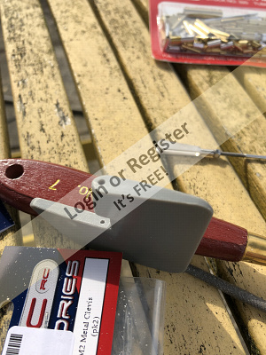
The last few weeks have been taken up by trying to complete the fore and aft sections so that I can complete the first part of the build and have a completed hull. At the end of the last update, I mentioned that I had broken the dive planes in half. I checked the rigidity of the remaining stub and decided it had enough strength to stay. I prepared a 15mm length of 5mm brass tube which nicely fitted over the remaining lugs. I glued a piece of 4mm diameter aluminium rod inside so that I could drill a small hole in the middle to hold the control arm. I then glued the whole assembly together and had a nice strong dive plane again. I then filed out the bearing surfaces in the main sections to accommodate the larger shafts.
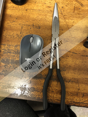
I finished of the whole assembly with control arms and proceeded to fit the prop shafts and the rear bearing assemblies. This took a fair bit of fiddling and reshaping of the angled hole through the hull but finally, after a few hours, I was happy with the results. I held the assemblies in place with elastic bands and then, when happy, used Stabilit Express glue to fix and fill. I make sure that I am fairly generous with the glue so that when I tidy it up, there are no holes left behind. I glued around the prop shaft assemblies on the inside as well and got a little bit of glue on the dive plane control arm. Whilst wiping this off, Disaster number 2. The control rod came out of its hole in the dive plane. This hole is 2mm diameter but 8” down inside of the aft section. Time for ebay. I found a pair of 11” long nosed pliers for £4.50. I bought immediately.
Today I decided to finish of the prop shafts by removing the excess glue. To do this I used small full round files, 240 grit wet and dry for roughing and 600 grit for finishing. This took a couple of hours but I am pleased with the results.
Now for the repair. I used the extra long nosed pliers and tried to find the hole whilst looking up the torpedo tube. Very difficult. I then noticed that if I shined a bright LED light into the section and looked at the side, the light showed right through the side wall of the model and the control arm pin could be seen as a shadow. With this, I managed to push the rod back into place. Phew!! I will have to think of a way I can get a little fluid super glue onto the rod without gluing the dive plane rigid.
My attention has now moved to the bow section. I have decided not to add retractable bow planes as this requires a lot of work for very little gain. I have, however, decided to fix the lift mechanisms in such a way that I can add retractable units at a later date. I hope for the next update I can complete this section and complete the hull section ready for splitting.
The WTC is still under construction but I am getting help from Doug (Mr Fleet Admiral SIR) for the electronics to get it to do what I want it to do. The next ballast unit test might also feature in the next update.
Thanks for reading.
Peter.😀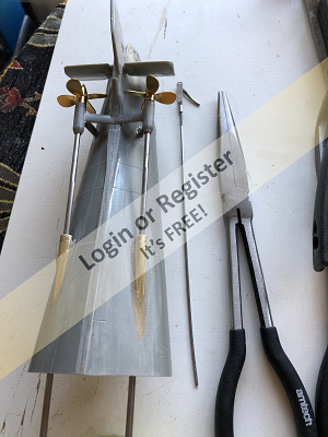
▲
⟩⟩
Scratchbuilder
mturpin013
figtree7nts
Martin555
jbkiwi
|
💬 Re: Completing the Aft Section.
5 years ago by 🇭🇺 MouldBuilder (
Vice Admiral)✧ 36 Views · 1 Like
Flag
At the moment I still have my factory Mike but not for too much longer. I will retire in the next few years and will have to do everything on bench machines. Looking forward to it really.😊
▲
⟩⟩
Martin555
|
|
Login To
Remove Ads 💬 Re: Completing the Aft Section.
5 years ago by 🇬🇧 mturpin013 (
 Admiral) Admiral)✧ 37 Views · 2 Likes
Flag
I had not followed this from the start as I'm not a sub mariner. However, having now read it from the beginning I found it most interesting. There's been some very nice machine work been carried out, I'm most jealous of your surface grinder, I have most engineering machines but I can't justify a surface grinder, but nice to have
Applause for some nice work👍 ▲
⟩⟩
Martin555
MouldBuilder
|
|
💬 Re: Completing the Aft Section.
5 years ago by 🇬🇧 Martin555 (
Fleet Admiral)✧ 37 Views · 1 Like
Flag
Well Peter despite having some tricky problems with the build you are making excellent progress.
Keep it up. Martin555. ▲
⟩⟩
Rookysailor
|
📝 Completing the Hull.
5 years ago by 🇭🇺 MouldBuilder ( Vice Admiral)
Vice Admiral)✧ 36 Views · 3 Likes · 3 Comments
Flag
💬 Add Comment
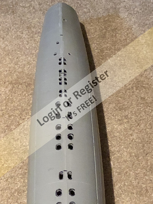
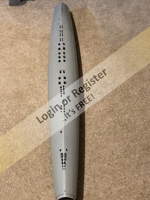
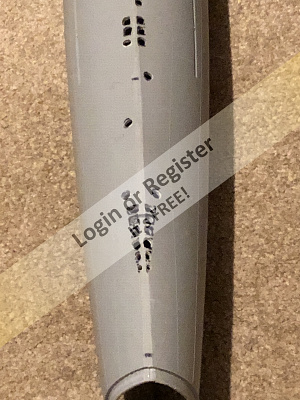
The last thing to do before completing the hull was to cut all of the vent slots on the underside. I used various sized drills and chain drilled the larger slots and filed them to shape. There is still a lot of shaping by file to do but I am going to leave this for later when I am sure they will be easier to get at.
I finally took the plunge and fixed the bow and stern assemblies to the main hull section. I used ordinary solvent cement which does create a strong bond, but will reinforce the joints with Stabilit once they become visible again. The next stage was to glue on the three main deck parts. It was a bit of a struggle to line them up exactly but In did the best I could. When gluing, care had to be taken to avoid contact at the front and rear segments so that a clean separation can be achieved when splitting the hull.
Next job was to do the vertical cuts at the separation lines. I used my Dremel with a saw blade as usual. These cuts will form the end points for the main cuts.
The next job for me is, as mentioned above, to split the hull. This is quite a tricky operation and requires a couple of special devices to be made. I am lucky enough to have all the machines required to make these at my disposal. I have started by cutting up the necessary pieces of wood. I will explain all on the next update when I have completed the separation.
Thanks for reading.
Peter.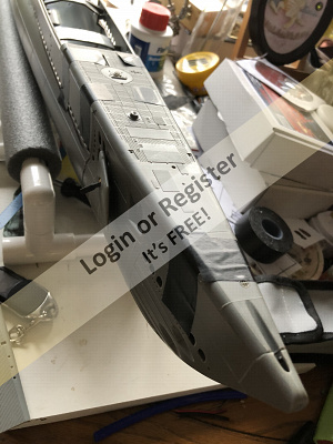
▲
⟩⟩
jbkiwi
Martin555
Scratchbuilder
|
💬 Re: Completing the Hull.
4 years ago by 🇿🇦 redpmg (
 Commodore) Commodore)✧ 37 Views · 3 Likes
Flag
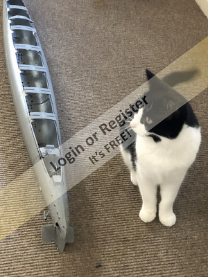
Like your build Peter - first thought that you might have stolen my quality inspector - Willy even turns his head upside down checking on things to make sure they are correct - on a cold night a week ago he pulled my body-warmer off the back of a chair and inserted himself into it - you can see the resemblance !


▲
⟩⟩
MouldBuilder
jbkiwi
Martin555
|
|
Login To
Remove Ads 💬 Re: Completing the Hull.
5 years ago by 🇳🇿 jbkiwi (
Fleet Admiral)✧ 37 Views · 2 Likes
Flag
I see the QC officer is there making sure everything is purrrfect😊 (sorry) Looks like a lot of work to convert these. Looking good so far.
JB ▲
⟩⟩
Martin555
redpmg
|
|
💬 Re: Completing the Hull.
5 years ago by 🇬🇧 Martin555 (
Fleet Admiral)✧ 37 Views · 1 Like
Flag
Hi Peter,
You are doing a really good job on the Gato conversion. It is surprising the amount of work required to convert it from a static model to radio control. Keep up the good work Peter. Martin555. ▲
⟩⟩
MouldBuilder
|


Login To
Remove Ads
Remove Ads