Join Us On Social Media!

|

|

|
Download The App!
Login To
Remove Ads
Remove Ads
Login To
Remove Ads
Remove Ads
Model Boats Website
34 inch Crash Tender refit
12 Posts · 9 Followers · 82 Photos · 107 Likes
Began 5 years ago by
 United Kingdom
Follow This Thread
Not currently following
> Click to follow
> Click to follow
Latest Post 4 years ago by
| Oldest posts shown first (Show Newest First) | (Print Booklet) |
📝 34 inch Crash Tender refit
5 years ago by 🇬🇧 Graham93 ( Vice Admiral)
Vice Admiral)✧ 31 Views · 6 Likes · 6 Comments
Flag
💬 Add Comment
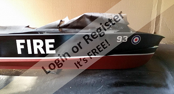
I posted a some pictures of my Crash Tender a few months ago and it was suggested that I should do a blog. So here we go.
This is my first blog, and my first boat. I am not going to provide a blow by blow account of the refit, as this would largely turn into a repeat of the excellent blogs by Rob (Robbob) and Mike (mturpin013). These two blogs have been a great inspiration and source of guidance for me over the past couple of months.
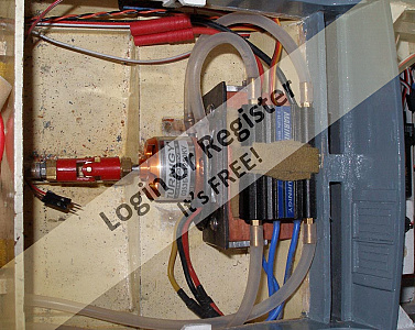
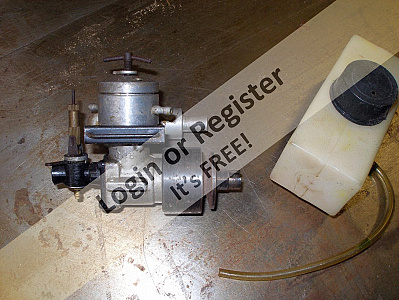
I built the boat in the early 1970s, but haven't had it on the water for nearly 45 years. Until recently, it had been collecting dust in my garage for all that time. The first task, having given it a good was to remove most of the dust, was to remove the ED Racer diesel engine, fuel tank, exhaust, etc and to fill in the exhaust hole in the transom. The diesel had always been a challenge to start, and to keep running. That, together with the unreliable, home built 27MHz radio gear is the reason the boat had been in dry dock for 45 years. A new brushless motor, water cooled ESC and 3S LiPo battery were installed in place of the diesel.
The propeller also needed replacing as the old one was too large. This identified the first problem. Times have changed since the 1970s and props now have metric threads, whereas my 1970s propshaft had a 4BA thread at both ends. A new 4mm silver steel shaft was fitted threaded M4 at each end. The new shaft diameter necessitated also replacing the plastic bushes in the shaft outer. Plastic bushes were probably not a good idea in any case. New phosphor bronze bushes were turned and fitted and it was then time to get it back on the water.
The first trial was very encouraging. The modern radio worked well, the boat was easy to start, quiet, and performed better than it ever had with the old gear. When I originally built it, I did not fit chine strakes. I cannot remember now why. It may be I didn't realise they should be fitted, or perhaps I felt they would spoil the smooth lines of the hull! Even without them it did manage to plane a little. Being fired up with enthusiasm after this first trial, I decided it was time to get back into the workshop, fit the missing strakes and start the refit proper.

This is my first blog, and my first boat. I am not going to provide a blow by blow account of the refit, as this would largely turn into a repeat of the excellent blogs by Rob (Robbob) and Mike (mturpin013). These two blogs have been a great inspiration and source of guidance for me over the past couple of months.
I built the boat in the early 1970s, but haven't had it on the water for nearly 45 years. Until recently, it had been collecting dust in my garage for all that time. The first task, having given it a good was to remove most of the dust, was to remove the ED Racer diesel engine, fuel tank, exhaust, etc and to fill in the exhaust hole in the transom. The diesel had always been a challenge to start, and to keep running. That, together with the unreliable, home built 27MHz radio gear is the reason the boat had been in dry dock for 45 years. A new brushless motor, water cooled ESC and 3S LiPo battery were installed in place of the diesel.
The propeller also needed replacing as the old one was too large. This identified the first problem. Times have changed since the 1970s and props now have metric threads, whereas my 1970s propshaft had a 4BA thread at both ends. A new 4mm silver steel shaft was fitted threaded M4 at each end. The new shaft diameter necessitated also replacing the plastic bushes in the shaft outer. Plastic bushes were probably not a good idea in any case. New phosphor bronze bushes were turned and fitted and it was then time to get it back on the water.
The first trial was very encouraging. The modern radio worked well, the boat was easy to start, quiet, and performed better than it ever had with the old gear. When I originally built it, I did not fit chine strakes. I cannot remember now why. It may be I didn't realise they should be fitted, or perhaps I felt they would spoil the smooth lines of the hull! Even without them it did manage to plane a little. Being fired up with enthusiasm after this first trial, I decided it was time to get back into the workshop, fit the missing strakes and start the refit proper.
▲
⟩⟩
Back in the Groove
Colin H
BOATSHED
Martin555
robbob
mturpin013
|
💬 Re: 34 inch Crash Tender refit
5 years ago by 🇩🇪 RNinMunich (
 Fleet Admiral) Fleet Admiral)✧ 28 Views · 3 Likes
Flag
"I find I enjoy the building more than the sailing. After all, all it can do is go round and round, faster or slower!"
Heartily agree Graham 👍 That's why my first ship build was a destroyer, thought it offered good possibilities for special functions. What happened? At 15 I had no resources for RC to even drive it round in 'wobbly' circles 🤔 She was free running and if she conked out Mum and I would stretch yards of Grandads fishing line across the boating lake at Radnor Park in Folkestone to haul her back in again! Caused some hilarity amongst the park strollers and littl' ol' ladies sitting on benches around the pond. Highly 'embrassing'! 😁 Some twenty years later, after moving to Germany and doubling my salary, RC was added along with traversing gun turret, NAV lights, flashing signal lamps, smoking funnel, Whoop Whoop siren and fog horn and an experimental towing winch. The latter since landed- a) I needed a weight like a can of baked beans to pull the winch hook out b) The stern of a destroyer is much too low to get the hook on to any other boat. Of course I discovered that on sea trials after spending time building my own winch controller🤔 Here endeth the night's ramblings of the old sea dog. Thank you for your patience 😌 😎 ▲
⟩⟩
BOATSHED
jbkiwi
Martin555
|
|
Login To
Remove Ads 💬 Re: 34 inch Crash Tender refit
5 years ago by 🇬🇧 Martin555 (
Fleet Admiral)✧ 28 Views · 2 Likes
Flag
Well said Fleet.
It is this site that keeps me going. Martin555. ▲
⟩⟩
BOATSHED
RNinMunich
|
|
💬 Re: 34 inch Crash Tender refit
5 years ago by 🇩🇪 RNinMunich (
Fleet Admiral)✧ 28 Views · 2 Likes
Flag
"Yes, the enthusiasm to dust it off and refit it came from finding this website."
Then we have reached our objective Graham 😊 to paraphrase my NAVI! 😉 Nice work 👍 PS I never managed to drive in circles, at best wobbly ellipses 🤔 Maybe operating next to the Biergarten had something to do with it! 😁😋 

▲
⟩⟩
BOATSHED
Martin555
|
|
💬 Re: 34 inch Crash Tender refit
5 years ago by 🇬🇧 Graham93 (
Vice Admiral)✧ 29 Views · 3 Likes
Flag
Yes, the enthusiasm to dust it off and refit it came from finding this website.
I find I enjoy the building more than the sailing. After all, all it can do is go round and round, faster or slower! Going to add working/rotating monitors and searchlight eventually, then it will do more than just go round in circles 😂 ▲
⟩⟩
RNinMunich
BOATSHED
Martin555
|
|
💬 Re: 34 inch Crash Tender refit
5 years ago by 🇬🇧 tidtug (
 Chief Petty Officer 2nd Class) Chief Petty Officer 2nd Class)✧ 28 Views · 2 Likes
Flag
Looks lovely after its refit has it give you a new burst of enthusiasm for the hobby?
▲
⟩⟩
BOATSHED
Martin555
|
|
💬 Re: 34 inch Crash Tender refit
5 years ago by 🇬🇧 mturpin013 (
 Admiral) Admiral)✧ 28 Views · 2 Likes
Flag
Good to see another boat back on the water
▲
⟩⟩
BOATSHED
Martin555
|
Login To
Remove Ads
Remove Ads
📝 Chine strakes and hull painting
5 years ago by 🇬🇧 Graham93 ( Vice Admiral)
Vice Admiral)✧ 32 Views · 8 Likes · 7 Comments
Flag
💬 Add Comment
Following the initial trial, I fitted chine strakes. These were steamed, bent to shape and left to dry. The original hull painting (humbrol enamel) was rubbed down and the new strakes fitted with epoxy and brass pins. I hope they will hold on the old paint surface. The gunwale strakes were also replaced as these had suffered from some damage over the years.
I also took the opportunity to replace the old cooling water outlet with something more to scale. Two exhaust ports were made using a couple of white metal portholes adapted with brass tubes which pass through the transom. The cooling water is fed out through both of these. I know this is not strictly accurate, as there should be a separate, smaller outlet for the engine cooling water, but I'm not looking to achieve 100% accuracy, just something that looks a lot more like scale than the original 45 year old model. I might revisit this at a later date.
The hull was painted using rattle cans, first a grey etch primer, then the colours followed by the decals and finally a clear lacquer coat. The hull was left to dry for two weeks and then it was back onto the water. As this is my only boat, I'm trying to carry out the refit in a way that allows me to get onto the water as often as I can.
The improvement in performance with the new chine strakes was remarkable. It now planes easily and turns quickly. With the diesel fitted it was reluctant to plane, and it could be difficult to turn which was due I think to the torque on the larger prop plus the missing strakes. What a difference hindsight (and this website!) makes. 😀 Another improvement was that the boat is now dry inside. It always used to fill the rear cockpit and the centre cabin with water but that is no longer the case. The two O-rings I added to the top and bottom of the rudder shaft may also have helped with this.
Returning from this outing I was unhappy to find that the foam protectors on the boat stand had marked the lacquer finish. Despite having left it for two weeks, it was still soft enough to be marked. Not sure if you can see the damage in the photo. Another detail I will have to revisit later.
I noticed that the motor was running a little warm so the opportunity was taken to replace the aluminium plate motor mount with one made from copper sheet with a copper tube silver soldered onto it. This has been plumbed into the ESC cooling water circuit and now keeps the motor reasonably cool.
The deck was then masked and painted with a textured finish followed by brush applied humbrol enamel. I found a tin of grey enamel in the garage, which must date from the original build, and it was still useable!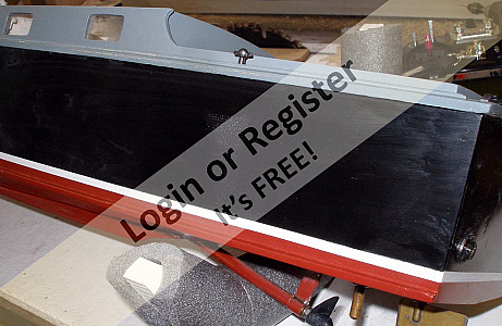
▲
⟩⟩
Back in the Groove
Colin H
RNinMunich
BOATSHED
mturpin013
jbkiwi
Martin555
robbob
|
💬 Re: Chine strakes and hull painting
5 years ago by 🇩🇪 RNinMunich (
Fleet Admiral)✧ 28 Views · 2 Likes
Flag
"Body repairers use an infra red lamp to dry and cure base coat and clear coat finishes before they polish it to a high gloss finish"
I use a couple of 300W halogen lamps to speed up the process Rob. Followed by a two stage polishing process using pro polishing pastes from the auto branch. Tricks I learned when restoring old bangers in my otherwise misspent youth😉 Details in my Sea Scout Jessica restoration Blog. The major ingredient is generous dollops of PATIENCE!! Cheers, Doug 😎 
▲
⟩⟩
BOATSHED
Martin555
|
|
Login To
Remove Ads 💬 Re: Chine strakes and hull painting
5 years ago by 🇳🇿 jbkiwi (
Fleet Admiral)✧ 27 Views · 1 Like
Flag
I like your exhaust treatment. I was trying to find a similar suitable surround for the pipes on my ST, but might have to substitute small drilled washers instead, (a when I can be bothered job)
JB ▲
⟩⟩
BOATSHED
|
|
💬 Re: Chine strakes and hull painting
5 years ago by 🇬🇧 mturpin013 (
Admiral)✧ 27 Views · 1 Like
Flag
Graham, the boat is looking great, as others have said a new coat always improves things. I can also confirm the issue with spray tins (Acrylic) as the boat Ive just finiashed for my grandson had the same issue. Im am spraying my crash tender with commercial cellulose using compressor and spray gun and although the drying time is also an issue in terms of time after a couple of weeks it hard enough to treat with flatting compond to achieve that polished finish
▲
⟩⟩
BOATSHED
|
|
💬 Re: Chine strakes and hull painting
5 years ago by 🇬🇧 Graham93 (
Vice Admiral)✧ 27 Views · 1 Like
Flag
Looks better in the photos than it does in reality. I don’t like rattle cans. The original paint job, hand painted with Humbrol enamel was much better when it was first done. But you are right, it does look a whole lot better than it did a few months ago.
▲
⟩⟩
BOATSHED
|
|
💬 Re: Chine strakes and hull painting
5 years ago by 🇳🇿 jbkiwi (
Fleet Admiral)✧ 28 Views · 2 Likes
Flag
Paint looks really good. Boat won't know itself!
JB ▲
⟩⟩
BOATSHED
Martin555
|
|
💬 Re: Chine strakes and hull painting
5 years ago by 🇬🇧 Martin555 (
Fleet Admiral)✧ 27 Views · 1 Like
Flag
What a difference a clean and a fresh coat of paint makes.
Good work, well done. Martin555. ▲
⟩⟩
BOATSHED
|
|
💬 Re: Chine strakes and hull painting
5 years ago by 🇬🇧 robbob (
Admiral)✧ 28 Views · 3 Likes
Flag
Hi Graham.
I'm pleased to see that you have started a 'refit' blog, and from what you've posted so far shows a remarkable improvement. The addition of the chine strakes have clearly been a worthwhile addition too. I also had a similar issue with the Halfords gloss lacquer coat being very 'soft' for a long time and easily marked, the hardening process does seems to take some time and so I did have to flat down the gloss lacquer on my boat and re-finish it too. Body repairers use an infra red lamp to dry and cure base coat and clear coat finishes before they polish it to a high gloss finish as I found out when I had a small repair done on my car by a mobile 'Chips Away' type repair company. They advised me that the drying/curing process does take time if the finish isn't 'baked' in a paint shop spray booth/oven. Curiously the red anti fouling on mine was finished with a satin lacquer and didn't suffer from any such problems and the hull sits on some neoprene pads on the stand with no ill effects. Keep up the great work👍. Robbob. ▲
⟩⟩
Colin H
BOATSHED
Martin555
|
📝 Wheelhouse
5 years ago by 🇬🇧 Graham93 ( Vice Admiral)
Vice Admiral)✧ 68 Views · 8 Likes · 3 Comments
Flag
💬 Add Comment
Having completed the basic hull repaint, it was time to get on to some of the more interesting details. Many of the deck fittings, ventilators, Samson post, etc were sourced from the shop on this website. These plastic fittings were primed with a grey etch primer and then top coated with Tamiya Gunmetal or Humbrol white enamel as appropriate.
Being the 1/16th scale Crash Tender, I don't have the benefit of having a set of white metal fittings. I wasn't able to find many off the shelf fittings in 1/16th scale so decided to scratch build them instead. It makes the job more interesting, if a bit fiddly, ....... and very time consuming!
The first task was to replace the fixed wheelhouse roof with a removeable one. This gives access to the interior of the wheelhouse for fitting lighting, new windows, and the searchlight servo. The window frames were cut from 1mm plasticard and painted silver.
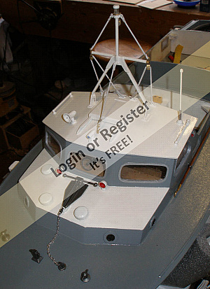
The mast was built from brass, including making the pulleys. A 5mm white LED is fitted to the top, with a little white painted brass cap to make it look the part. Rigging is 1.5mm elastic cord. I think this is a little thick and 1mm might look better. I still have to source the ensign to fly from the mast. There is a pulley in place ready for it.
The port, starboard and wheelhouse roof navigation lights were all constructed using plasticard and fitted with 3mm LEDs. The aerial on the roof of the wheelhouse is made from brass based on the details given by Mike (mturpin013) in his blog.
The boathooks were also scratchbuilt from brass. I thought they would look better than the white metal ones available on eBay. For the "shepherd's crook" hook, the brass rod was first tapered by filing and sanding before being bent to the appropriate shape. The other hook was formed by silver soldering a brass cross piece onto a tapered shaft. Both hooks were formed on the end of a long length of brass rod to make it easier to handle them. Once complete, a short section of rod behind the hook was turned down to 1mm dia to form a spigot for mounting on the poles. The poles were carved from mahogany.
With all these details in place it is really beginning to look the part. Next up the rear deck.

Being the 1/16th scale Crash Tender, I don't have the benefit of having a set of white metal fittings. I wasn't able to find many off the shelf fittings in 1/16th scale so decided to scratch build them instead. It makes the job more interesting, if a bit fiddly, ....... and very time consuming!
The first task was to replace the fixed wheelhouse roof with a removeable one. This gives access to the interior of the wheelhouse for fitting lighting, new windows, and the searchlight servo. The window frames were cut from 1mm plasticard and painted silver.
The mast was built from brass, including making the pulleys. A 5mm white LED is fitted to the top, with a little white painted brass cap to make it look the part. Rigging is 1.5mm elastic cord. I think this is a little thick and 1mm might look better. I still have to source the ensign to fly from the mast. There is a pulley in place ready for it.
The port, starboard and wheelhouse roof navigation lights were all constructed using plasticard and fitted with 3mm LEDs. The aerial on the roof of the wheelhouse is made from brass based on the details given by Mike (mturpin013) in his blog.
The boathooks were also scratchbuilt from brass. I thought they would look better than the white metal ones available on eBay. For the "shepherd's crook" hook, the brass rod was first tapered by filing and sanding before being bent to the appropriate shape. The other hook was formed by silver soldering a brass cross piece onto a tapered shaft. Both hooks were formed on the end of a long length of brass rod to make it easier to handle them. Once complete, a short section of rod behind the hook was turned down to 1mm dia to form a spigot for mounting on the poles. The poles were carved from mahogany.
With all these details in place it is really beginning to look the part. Next up the rear deck.
▲
⟩⟩
BOATSHED
Colin H
rikster67
RNinMunich
jbkiwi
Martin555
figtree7nts
robbob
|
💬 Re: Wheelhouse
5 years ago by 🇬🇧 mturpin013 (
Admiral)✧ 65 Views · 3 Likes
Flag
Coming together nicely, I agree it’s often more interesting and rewarding to make your own parts.
▲
⟩⟩
BOATSHED
Martin555
RNinMunich
|
|
Login To
Remove Ads 💬 Re: Wheelhouse
5 years ago by 🇳🇿 jbkiwi (
Fleet Admiral)✧ 64 Views · 3 Likes
Flag
Nice job on the parts, sometimes easier to make your own bits, - nothing worse than ordering o/s, waiting a month then finding the part is the wrong size. Bit of a gamble sometimes. Not so bad if you build to a common scale and parts are ready made to suit.
I think a bit of personal input adds to the boats character, as buying too many bits can make your model partly someone elses' work, (unless there is no other option). JB ▲
⟩⟩
BOATSHED
Martin555
Colin H
|
|
💬 Re: Wheelhouse
5 years ago by 🇬🇧 Martin555 (
Fleet Admiral)✧ 64 Views · 1 Like
Flag
Nice work, well done.
Keep up the good work. Martin555. ▲
⟩⟩
BOATSHED
|
📝 Rear Deck
5 years ago by 🇬🇧 Graham93 ( Vice Admiral)
Vice Admiral)✧ 68 Views · 10 Likes · 10 Comments
Flag
💬 Add Comment
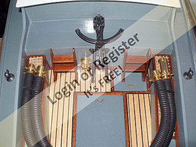
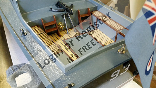
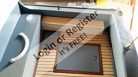
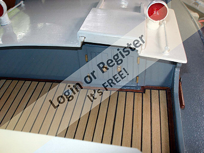
The rear deck gives plenty of opportunity for adding some model detail. The original cockpit floor was plain painted grey with a 'power bulge' to cover the 1970's rudder servo. A new smaller servo and servo mount were installed to allow a flat floor to replace the original power bulge version. The new floor has been planked with lime strips grouted with 0.5mm black plasticard. The central hatch is easily removable to check that the servo compartment is dry. It is held in place with magnets.
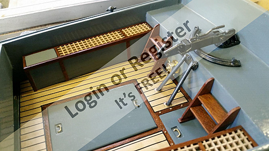
The two foam tanks are made from 2mm ply with mahogany trim and pieces of a commercial grating fixed on top. The tanks are also held in place with magnets.
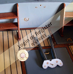
The ladders are 2mm mahogany with the runners glued and pinned to the sides with brass pins. The ladders are mounted using M1.6 threaded rod glued to the bottom of the ladders and passing through the cockpit floor. Foot pads had to be added to the bottom of the ladders to provide a sufficiently large fixing point for the threaded rod. Springs on the underside of the floor hold the ladders in place with the top of the ladders simply pressing against the bulkhead. This allows the cockpit floor to be removed with the ladders in one piece.
The towhook is made from plasticard, with a few details added with brass rod and M1.6 nuts. The towhook stays are also plasticard. They locate into brass bushes in the cockpit floor with the top end held with a locating pin and two small magnets.
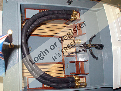
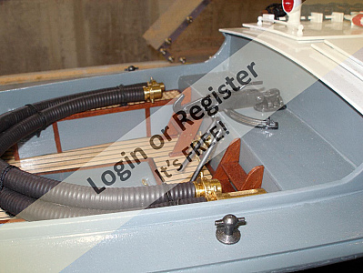
The hose fittings were turned from brass using Robbob's drawings with the dimensions scaled down to 1/16th scale. The hoses are the normal coiled wire covered with black heatshrink. A brass hook at the rear of the cockpit holds the hoses in place. I was concerned that this was not sufficient in itself and do not want to loose these hoses in the lake, so black elastic cords were looped through the tops of the foam tanks. These loops pass round the hoses and hold them securely. The hose bulkhead fitting has a 5mm round magnet set into it's rear face which holds it in position against a similar magnet set into the bulkhead.
Using magnets for fixing the foam tanks, the towhook stays and the hose bulkhead fitting allows them all to be quickly removed thus allowing the cockpit floor to also be removed for access to the steering servo.
My thanks to Robbob and MTurpin103 for their excellent Crash Tender blogs. Much of this work on the rear deck has been based on their blogs.


The two foam tanks are made from 2mm ply with mahogany trim and pieces of a commercial grating fixed on top. The tanks are also held in place with magnets.
The ladders are 2mm mahogany with the runners glued and pinned to the sides with brass pins. The ladders are mounted using M1.6 threaded rod glued to the bottom of the ladders and passing through the cockpit floor. Foot pads had to be added to the bottom of the ladders to provide a sufficiently large fixing point for the threaded rod. Springs on the underside of the floor hold the ladders in place with the top of the ladders simply pressing against the bulkhead. This allows the cockpit floor to be removed with the ladders in one piece.
The towhook is made from plasticard, with a few details added with brass rod and M1.6 nuts. The towhook stays are also plasticard. They locate into brass bushes in the cockpit floor with the top end held with a locating pin and two small magnets.
The hose fittings were turned from brass using Robbob's drawings with the dimensions scaled down to 1/16th scale. The hoses are the normal coiled wire covered with black heatshrink. A brass hook at the rear of the cockpit holds the hoses in place. I was concerned that this was not sufficient in itself and do not want to loose these hoses in the lake, so black elastic cords were looped through the tops of the foam tanks. These loops pass round the hoses and hold them securely. The hose bulkhead fitting has a 5mm round magnet set into it's rear face which holds it in position against a similar magnet set into the bulkhead.
Using magnets for fixing the foam tanks, the towhook stays and the hose bulkhead fitting allows them all to be quickly removed thus allowing the cockpit floor to also be removed for access to the steering servo.
My thanks to Robbob and MTurpin103 for their excellent Crash Tender blogs. Much of this work on the rear deck has been based on their blogs.
▲
⟩⟩
BOATSHED
Back in the Groove
MouldBuilder
jbkiwi
RNinMunich
Rookysailor
mturpin013
robbob
Colin H
Martin555
|
💬 Re: Rear Deck
5 years ago by 🇭🇺 MouldBuilder (
Vice Admiral)✧ 64 Views · 2 Likes
Flag
Really nice detailing. Looks superb.
▲
⟩⟩
BOATSHED
Martin555
|
|
Login To
Remove Ads 💬 Re: Rear Deck
5 years ago by 🇩🇪 RNinMunich (
Fleet Admiral)✧ 64 Views · 2 Likes
Flag
"I have found that it needs frequent stirring otherwise you end up with a plain dark grey finish. "
Natch! Otherwise all the metal particles sink quickly to the bottom again. I have the same aggro with Hammerite and some new (expensive 🤔) chrome paint I am experimenting with. Nice job Graham👍 ▲
⟩⟩
BOATSHED
Martin555
|
|
💬 Re: Rear Deck
5 years ago by 🇳🇿 jbkiwi (
Fleet Admiral)✧ 64 Views · 2 Likes
Flag
Brilliant resto job, fantastic detail!
JB ▲
⟩⟩
BOATSHED
Martin555
|
|
💬 Re: Rear Deck
5 years ago by 🇬🇧 Graham93 (
Vice Admiral)✧ 64 Views · 3 Likes
Flag
Peter,
Thanks. The paint is brush applied Tamiya acrylic in Gunmetal Grey X10 applied over grey etch primer from a rattle can. I’m pleased with the effect. It is thin, goes on easily without obscuring detail and dries quickly. I have found that it needs frequent stirring otherwise you end up with a plain dark grey finish. ▲
⟩⟩
BOATSHED
Rookysailor
Martin555
|
|
💬 Re: Rear Deck
5 years ago by 🇬🇧 Rookysailor (
 Commodore) Commodore)✧ 64 Views · 2 Likes
Flag
What a terrific job you have done Graham, love the towhook.
What paint did you use to get that finish? it looks like it's made of metal, Brill👍 Peter (Rooky)😐 ▲
⟩⟩
BOATSHED
Martin555
|
|
💬 Re: Rear Deck
5 years ago by 🇬🇧 Graham93 (
Vice Admiral)✧ 65 Views · 3 Likes
Flag
Mike,
This has taken most of my spare time over the past three months, indeed I have really spent more time on it than I should have, with many domestic jobs not getting done. And I haven’t had the distraction of having to build a boat for my grandson like you have. He wants to sail this one, which I’m not sure is a good idea 😉 ▲
⟩⟩
BOATSHED
Martin555
RNinMunich
|
|
💬 Re: Rear Deck
5 years ago by 🇬🇧 mturpin013 (
Admiral)✧ 64 Views · 2 Likes
Flag
Really good work, I wish I could go at that speed, Im hoping to have mine finished for next summer🤞
▲
⟩⟩
BOATSHED
Martin555
|
|
💬 Re: Rear Deck
5 years ago by 🇬🇧 robbob (
Admiral)✧ 64 Views · 2 Likes
Flag
Hi Graham.
I'm pleased and flattered 😊 that you have been able to take inspiration from my build blog, I'm sure Mike Turpin is too. Excellent workmanship too, the first two 'photos 'before and after' are testament to your abilities. Kind Regards. Rob. ▲
⟩⟩
BOATSHED
Martin555
|
|
💬 Re: Rear Deck
5 years ago by 🇬🇧 Graham93 (
Vice Admiral)✧ 65 Views · 2 Likes
Flag
Thanks Martin. It has been a challenge, but it has kept me out of mischief for the past few months. Not finished yet, but I’m already planning the next project. Trying to be good though and making sure I finish this job before I start the next one...
▲
⟩⟩
BOATSHED
RNinMunich
|
|
💬 Re: Rear Deck
5 years ago by 🇬🇧 Martin555 (
Fleet Admiral)✧ 64 Views · 2 Likes
Flag
Hi Graham,
WOW! What a difference. I would not recognise that as the same boat. Excellent workmanship. Well done. Martin555. ▲
⟩⟩
BOATSHED
Rookysailor
|
📝 Midships
5 years ago by 🇬🇧 Graham93 ( Vice Admiral)
Vice Admiral)✧ 69 Views · 11 Likes · 5 Comments
Flag
💬 Add Comment
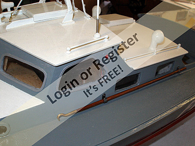
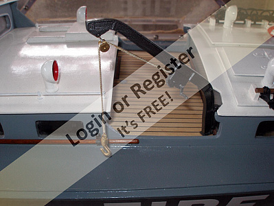
When the boat was fitted with a diesel there was no deck between the forward cabin and the engine room. This was to allow room for the engine cylinder head. So the first task was to construct a planked deck to fill the space. The opportunity was also taken to add the cabin door detail, complete with dummy hinges and door knobs.
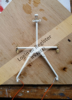
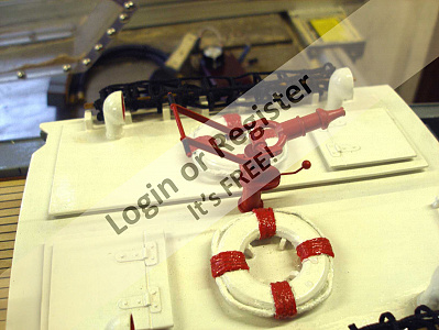
The davit was constructed from plasticard and painted gunmetal grey. Basic height and reach dimensions for this were taken from the plan. Details were added based on photos found on this site.
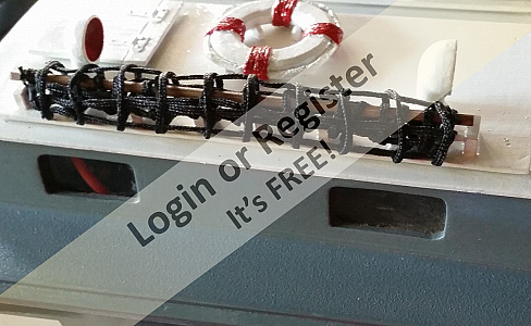
The scramble nets were made using black woven cord. This was laid out on a piece of scrap plywood using panel pins to space the cord into the desired net structure. The cord crossover joints were then glued with superglue. This didn't work well. The joints were not strong, some having to be re-glued. The dried glue caused a white stain on the cord. This was disguised with permanent black marker pen. A bigger issue was that the cord had absorbed the glue which wicked along the length from the joints making the net inflexible in parts. It would not roll up neatly and looked a mess. Fortunately I had enough cord left to make replacement nets. This time, each of the 100 crossover joints was sewn with black cotton thread. This took some time but the joints are now strong and the completed net is fully flexible.
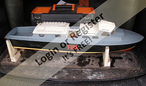
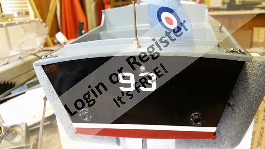
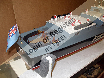
This post brings us up to present day with the refit. There is still more to do including the fire monitors and spotlight. Just to show it does sail, I've included a photo of it out on the lake yesterday. It is only running at approx. 1/4 throttle which doesn't show how it planes. I haven't yet mastered driving it at full speed while simultaneously taking photos!


The davit was constructed from plasticard and painted gunmetal grey. Basic height and reach dimensions for this were taken from the plan. Details were added based on photos found on this site.
The scramble nets were made using black woven cord. This was laid out on a piece of scrap plywood using panel pins to space the cord into the desired net structure. The cord crossover joints were then glued with superglue. This didn't work well. The joints were not strong, some having to be re-glued. The dried glue caused a white stain on the cord. This was disguised with permanent black marker pen. A bigger issue was that the cord had absorbed the glue which wicked along the length from the joints making the net inflexible in parts. It would not roll up neatly and looked a mess. Fortunately I had enough cord left to make replacement nets. This time, each of the 100 crossover joints was sewn with black cotton thread. This took some time but the joints are now strong and the completed net is fully flexible.
This post brings us up to present day with the refit. There is still more to do including the fire monitors and spotlight. Just to show it does sail, I've included a photo of it out on the lake yesterday. It is only running at approx. 1/4 throttle which doesn't show how it planes. I haven't yet mastered driving it at full speed while simultaneously taking photos!
▲
⟩⟩
Colin H
BOATSHED
Back in the Groove
mturpin013
jbkiwi
marky
Rookysailor
MouldBuilder
robbob
RNinMunich
Martin555
|
💬 Re: Midships
5 years ago by 🇳🇿 jbkiwi (
Fleet Admiral)✧ 64 Views · 1 Like
Flag
Brilliant rebuild, love the detail, looking forward to a video.
JB ▲
⟩⟩
BOATSHED
|
|
Login To
Remove Ads 💬 Re: Midships
5 years ago by 🇬🇧 marky (
Commodore)✧ 64 Views · 1 Like
Flag
Really nice Graham,don't know how I missed this earlier.
▲
⟩⟩
BOATSHED
|
|
💬 Re: Midships
5 years ago by 🇬🇧 Graham93 (
Vice Admiral)✧ 64 Views · 1 Like
Flag
Thanks Martin and thanks to everyone else for the positive feedback and encouragement.
Yes, I am pleased with the results so far. It looks a lot better, and sails a lot better than it did before the refit. Now it’s time to get on to the working monitors and searchlight. ▲
⟩⟩
BOATSHED
|
|
💬 Re: Midships
5 years ago by 🇩🇪 RNinMunich (
Fleet Admiral)✧ 64 Views · 2 Likes
Flag
What a transformation😮 Hat off Sir 👍
😎 BTW Like the new planked deck, especially the edging 👍 Solves my problem with my Sea Scout so I'm unashamedly gonna copy that 😉 Even an old sea dog like me can learn new tricks 😊 ▲
⟩⟩
BOATSHED
Martin555
|
|
💬 Re: Midships
5 years ago by 🇬🇧 Martin555 (
Fleet Admiral)✧ 64 Views · 1 Like
Flag
You are doing an excellent job Graham.
You must be pleased with the results so far. Keep up the good work. Martin555. ▲
⟩⟩
BOATSHED
|
📝 Fire Monitors Part 1
5 years ago by 🇬🇧 Graham93 ( Vice Admiral)
Vice Admiral)✧ 66 Views · 8 Likes · 9 Comments
Flag
💬 Add Comment
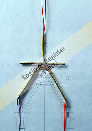
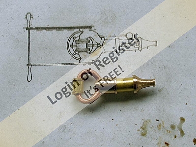
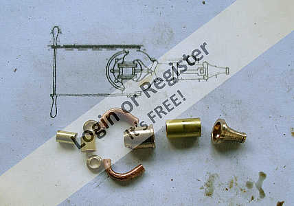
I want to have working fire monitors on the boat, so decided to make them in brass. I also want them to swivel. To give the right appearance, the water needs to pass through the vertical support column into the body of the monitor. I don't want a separate tube from the body of the monitor going through the cabin roof as it would not look accurate, and will likely restrict the rotation of the monitor.
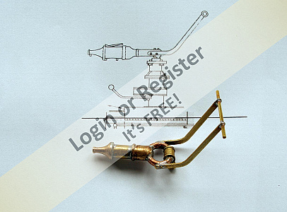
The body of the monitor is made from a short length of 6mm brass tube with two turned end caps. The front cap, the nozzle, was turned and filed to a suitable shape on the lathe. The inside is drilled out as much as I dared to reduce the weight. The nozzle outlet was initially drilled 0.6mm dia. During initial trials with the pump connected this was opened up to 0.85mm dia. to give an increased water flow without having any significant effect on the throw of the jet.
The rear end cap is also drilled out internally to reduce the weight. Two 3mm holes are drilled at 45 degrees at the rear of the cap to attach the curved copper pipes which will carry water from the vertical support column. Bending the 3mm copper tube to shape was tricky, it is a tight bend but I managed it without it collapsing too much. The tubes will need a bit of cleaning up before painting.
The connection to the vertical column is formed as a T piece from two short pieced of brass tube. These were soldered together using silver solder for strength. Two small turned flanges connect the copper tubes to this T piece.
The handles were cut from brass sheet with a length of 1.5mm brass rod as the cross piece. All the parts were soft soldered together. The completed monitor body was connected to the pump and tried out. One of the soldered joints was leaking and had to be remade. Having drilled out the nozzle to 0.85mm dia. the resulting water jet looks effective with a throw of around 2-3 feet.
▲
⟩⟩
Colin H
BOATSHED
RNinMunich
mturpin013
Martin555
Rookysailor
jbkiwi
robbob
|
💬 Re: Fire Monitors Part 1
5 years ago by 🇬🇧 Rookysailor (
Commodore)✧ 64 Views · 1 Like
Flag
Excellent video Rob, very interesting items, must think about going to the engineering show next January.😐
cheers, Peter ▲
⟩⟩
BOATSHED
|
|
Login To
Remove Ads 💬 Re: Fire Monitors Part 1
5 years ago by 🇬🇧 Graham93 (
Vice Admiral)✧ 64 Views · 1 Like
Flag
Peter,
The mini lathe has made all the difference to being able to make things like this. I couldn’t attempt it without it. I haven’t had it long, and I’m still a bit of a novice with it. What you can’t see in the blog is how much time it has taken to make these bits, and how many spoiled attempts there have been. I think the rotating support columns, together with the water connection will be quite a challenge. ▲
⟩⟩
BOATSHED
|
|
💬 Re: Fire Monitors Part 1
5 years ago by 🇬🇧 Graham93 (
Vice Admiral)✧ 64 Views · 1 Like
Flag
Rob,
Good to meet you on Saturday and to see your boat for real rather than just looking at the photos. We enjoyed the event at St Albans. It was great to see so many activities for the youngsters to have a go. Nice video of the boat. I especially like the on-board clips. I picked up some brass rounds at the show that will be used for parts for the fire monitor support columns. ▲
⟩⟩
BOATSHED
|
|
💬 Re: Fire Monitors Part 1
5 years ago by 🇬🇧 mturpin013 (
Admiral)✧ 64 Views · 1 Like
Flag
Very nice piece of work, Its funny that I am also doing exactly the same job at present.
▲
⟩⟩
BOATSHED
|
|
💬 Re: Fire Monitors Part 1
5 years ago by 🇬🇧 Martin555 (
Fleet Admiral)✧ 64 Views · 1 Like
Flag
Lovely bit of engineering,
Excellent workmanship. Keep it up. Martin555. ▲
⟩⟩
BOATSHED
|
|
💬 Re: Fire Monitors Part 1
5 years ago by 🇬🇧 Martin555 (
Fleet Admiral)✧ 64 Views · 2 Likes
Flag
Nice video Robbob,
A little something for everyone, Thank you for posting it. Martin555. ▲
⟩⟩
BOATSHED
Rookysailor
|
|
💬 Re: Fire Monitors Part 1
5 years ago by 🇬🇧 Rookysailor (
Commodore)✧ 64 Views · 2 Likes
Flag
A wonderful piece of modeling Graham, would love to make a pair for my fireboat, if only I had the ability
to produce such items.😐 cheers, Peter ▲
⟩⟩
BOATSHED
Martin555
|
|
💬 Re: Fire Monitors Part 1
5 years ago by 🇳🇿 jbkiwi (
Fleet Admiral)✧ 64 Views · 2 Likes
Flag
Very nice effort and a clever idea with the scale water supply.
▲
⟩⟩
BOATSHED
Martin555
|
|
💬 Re: Fire Monitors Part 1
5 years ago by 🇬🇧 robbob (
Admiral)✧ 65 Views · 4 Likes
Flag
Hi Graham.
Your fire monitors are excellent work as they are the first 'working' ones I've seen that actually look like they should. I think that the 'plinth' that it will sit on will present it's own problems with articulation and plumbing but you've cracked the hardest bit 👍 It was a pleasure meeting you at our club exhibition in St.Albans at the weekend and discussing our FireBoats, I know that you travelled a long way to see the show. I have put a report about the show on the club website with a video that I produced that has some shots of my Fireboat on the water and the Thames Police Launch on display. Keep up the great work. Rob. ▲
⟩⟩
BOATSHED
RNinMunich
Rookysailor
Martin555
|

📝 Fire Monitors Part 2
5 years ago by 🇬🇧 Graham93 ( Vice Admiral)
Vice Admiral)✧ 67 Views · 9 Likes · 17 Comments
Flag
💬 Add Comment
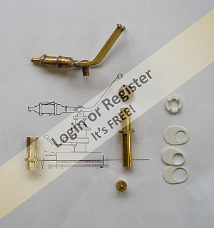
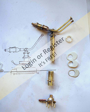
The fire monitor columns are constructed from two lengths of brass tube with various bits added, either for appearance, or for function. The short tube is 8mm o/d and has a brass collar added. This tube will eventually be glued into a hole in the cabin roof. I had to make these tubes a little longer than shown on the plan to ensure that the rotating monitor would not foul the lifebelts on the engine room roof.
The second, longer tube is 7mm o/d and forms the rotating column. It will slide into the shorter 8mm tube. It carries the water from below deck up to the monitor at the top of the tube. A brass bush is soldered into the top of the tube and the monitor body is soldered into that bush.
Part way down this tube, a brass collar is soldered to act as a bearing point against the top edge of the larger tube when everything is assembled. The bottom of the 7mm rotating tube was plugged with brass and then drilled and tapped with a female M5 thread.
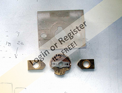
The servo coupling is a brass boss with a disc of 0.5mm brass sheet soldered on. This was then turned to be circular before 4 brass pins were added to engage with the servo arm. The top of the boss is threaded with an M5 male thread to screw into the rotating column. A short length of 3mm copper tube is attached to the side of the boos to provide the water connection point. The centre of the M5 screw is drilled out 3mm to allow the water to pass into the rotating column.
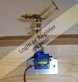
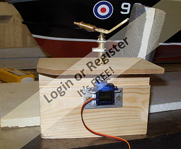
Plasticard was used to add some details to the columns and then the monitor was rigged up on a mock up of the cabin roof and connected to a servo to test out the rotation. An electronic servo pulse stretcher was built to give 180 degrees of rotation for the monitor. I would have liked a little more, but the servo doesn't seem capable of accepting more than 0.5 - 2.5mS pulse width.
Finally everything was stripped down, de-greased and painted using rattle cans. First with grey etch primer and then with 'Toolbox red' as suggested by Robbob. I have just realised, while writing this that I should not have painted the lower sections of the rotating tubes as these need to slide into the shorter tubes. Ah well, it will be easy enough to scrape that bit of paint off!
(I'm sorry that the photos are not ordered in the correct sequence for the description. It doesn't seem to matter how I name the photos, or upload them, they just take on a random order of their own. Anyone know a solution to this?)


The second, longer tube is 7mm o/d and forms the rotating column. It will slide into the shorter 8mm tube. It carries the water from below deck up to the monitor at the top of the tube. A brass bush is soldered into the top of the tube and the monitor body is soldered into that bush.
Part way down this tube, a brass collar is soldered to act as a bearing point against the top edge of the larger tube when everything is assembled. The bottom of the 7mm rotating tube was plugged with brass and then drilled and tapped with a female M5 thread.
The servo coupling is a brass boss with a disc of 0.5mm brass sheet soldered on. This was then turned to be circular before 4 brass pins were added to engage with the servo arm. The top of the boss is threaded with an M5 male thread to screw into the rotating column. A short length of 3mm copper tube is attached to the side of the boos to provide the water connection point. The centre of the M5 screw is drilled out 3mm to allow the water to pass into the rotating column.
Plasticard was used to add some details to the columns and then the monitor was rigged up on a mock up of the cabin roof and connected to a servo to test out the rotation. An electronic servo pulse stretcher was built to give 180 degrees of rotation for the monitor. I would have liked a little more, but the servo doesn't seem capable of accepting more than 0.5 - 2.5mS pulse width.
Finally everything was stripped down, de-greased and painted using rattle cans. First with grey etch primer and then with 'Toolbox red' as suggested by Robbob. I have just realised, while writing this that I should not have painted the lower sections of the rotating tubes as these need to slide into the shorter tubes. Ah well, it will be easy enough to scrape that bit of paint off!
(I'm sorry that the photos are not ordered in the correct sequence for the description. It doesn't seem to matter how I name the photos, or upload them, they just take on a random order of their own. Anyone know a solution to this?)
▲
⟩⟩
Colin H
BOATSHED
robbob
jbkiwi
Rookysailor
MouldBuilder
mturpin013
Martin555
RNinMunich
|
💬 Re: Fire Monitors Part 2
5 years ago by 🇬🇧 Graham93 (
Vice Admiral)✧ 64 Views · 1 Like
Flag
Mike,
No I haven’t. I don’t have any experience with sail winches. It looks like they will certainly rotate more than 180 degrees. I think the one you have found will do 4 x 360 degrees. You would need to be careful not to tie everything in knots with that. Found the attached video which shows the rotation. It looks like the servo takes a little while to complete its rotation which could make it a rotating monitor difficult to control. Regards Graham ▲
⟩⟩
BOATSHED
|
|
Login To
Remove Ads 💬 Re: Fire Monitors Part 2
5 years ago by 🇬🇧 mturpin013 (
Admiral)✧ 64 Views · 1 Like
Flag
Have you thought of using a sail servo. I'm just about to trial my system, (I just finished painting my efforts which will be in my blog shortly.) Looking at this type of servo it seems this one just rotates 360 degrees.
Or have I got this wrong? I'm just about to purchase one, so thoughts please before I do. ▲
⟩⟩
BOATSHED
|

|
💬 Re: Fire Monitors Part 2
5 years ago by 🇬🇧 Graham93 (
Vice Admiral)✧ 64 Views · 2 Likes
Flag
Thanks JB,
There is plenty of room, although I am gradually filling it up. I like the elastic suggestion and plan to fit an elbow to the copper tube inlet to turn the tube down. I just need to make sure it clears the servo while rotating. Regards Graham ▲
⟩⟩
BOATSHED
jbkiwi
|
|
💬 Re: Fire Monitors Part 2
5 years ago by 🇬🇧 Graham93 (
Vice Admiral)✧ 65 Views · 3 Likes
Flag
Thanks Rob,
Yes, I did try them before I painted them and was pleased with the water throw. If I was to make them again, I think I would arrange for the nozzle to screw on to the front of the monitor to allow it to be dismantled and flushed out. I’m going to fit a filter in the pipework but I suspect I’m going to have problems with blockages on the lake. Good point about securing the pipework. Would hate to watch the boat slowly sinking in the middle of the lake. Regards Graham ▲
⟩⟩
BOATSHED
robbob
jbkiwi
|
|
💬 Re: Fire Monitors Part 2
5 years ago by 🇳🇿 jbkiwi (
Fleet Admiral)✧ 64 Views · 1 Like
Flag
Really nice job!
▲
⟩⟩
BOATSHED
|
|
💬 Re: Fire Monitors Part 2
5 years ago by 🇳🇿 jbkiwi (
Fleet Admiral)✧ 64 Views · 1 Like
Flag
RE- Yes, the silicone tube will attach to the copper pipe and hence will have to swivel
Hi Graham, you could, if you have room in the cabin, just give the tube some slack and hang it from the roof with a thin rubber band, to tension it towards the end of the servo throw. This might keep it from hanging down and getting caught up. Thick wall silicone tube will stop any kinks. Alternatively if your inlet tube was facing down, the silicone tube could loop down then up over the rubber band and down again which would give you a better rotation of the silicone tube and be tensioned up out of the way. JB 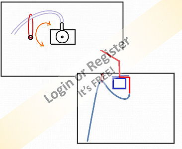
▲
⟩⟩
BOATSHED
|
|
💬 Re: Fire Monitors Part 2
5 years ago by 🇬🇧 robbob (
Admiral)✧ 64 Views · 2 Likes
Flag
Hi Graham.
I have to say that they look really true to the originals, have you done a 'hydraulic' test yet? Do use some clamps on the water connections though, you don't want them coming off and flooding the compartment 😮. I think Mike Turpin has a point about the servo travel but your home brew servo stretcher looks very useful indeed. Great work👍, Rob. ▲
⟩⟩
BOATSHED
jbkiwi
|
|
💬 Re: Fire Monitors Part 2
5 years ago by 🇩🇪 RNinMunich (
Fleet Admiral)✧ 64 Views · 2 Likes
Flag
"Being a retired electronics engineer I like to keep my hand in and make whatever I can in terms of controls. Makes it all a bit more interesting."
Copy that Graham👍 Welcome to the club 😉 Doug 😎 ▲
⟩⟩
BOATSHED
Martin555
|
|
💬 Re: Fire Monitors Part 2
5 years ago by 🇩🇪 RNinMunich (
Fleet Admiral)✧ 64 Views · 2 Likes
Flag
"The pulse stretcher is scratch built."
Excellent job Graham👍 I've been looking at some stretcher circuits using the good old 555/556 timer chips. @ Rooky: I too thought of the Action Electronics Pulse Stretcher, but it only goes out to 160° end to end🤔 Happy stretching folks 😊 Cheers, Doug 😎 ▲
⟩⟩
BOATSHED
Martin555
|
|
💬 Re: Fire Monitors Part 2
5 years ago by 🇬🇧 Graham93 (
Vice Admiral)✧ 65 Views · 5 Likes
Flag
Thanks Peter,
Component Shop have some great products for this sort of thing, and that device would give a good range of control. Being a retired electronics engineer I like to keep my hand in and make whatever I can in terms of controls. Makes it all a bit more interesting. Regards Graham ▲
⟩⟩
BOATSHED
mturpin013
jbkiwi
Martin555
RNinMunich
|
|
💬 Re: Fire Monitors Part 2
5 years ago by 🇬🇧 Graham93 (
Vice Admiral)✧ 65 Views · 4 Likes
Flag
Mike,
Yes, the silicone tube will attach to the copper pipe and hence will have to swivel. I am concerned about this getting into a tangle but I have a few ideas. I wasn't looking for as much as 270 degrees, but a bit more than 180 as shown in the picture. I think I'll stick with 180 for now and get it all installed and working. Can always upgrade it later if I'm bored! 
▲
⟩⟩
BOATSHED
jbkiwi
Martin555
RNinMunich
|
|
Login To
Remove Ads 💬 Re: Fire Monitors Part 2
5 years ago by 🇬🇧 Graham93 (
Vice Admiral)✧ 65 Views · 3 Likes
Flag
Doug,
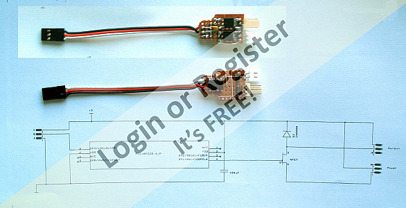
The pulse stretcher isn't the problem in this case. There aren't any mechanical end stops on the servo either. If you give it pulse widths over 2.5mS it will do 360 degree and more in uncontrolled rotations without any damage. No stalled motor or stripped gears. It seems to be the electronics in the servo that will only sensibly interpret pulse widths between 0.5 and 2.5mS. This range equates to 180 degree rotation. So if I want to get more, I either have to change the servo, or adopt one of the suggestions from you or Martin. The pulse stretcher is scratch built. A few lines of assembler code burnt into a baseline PIC10. Very basic, it takes in 1.0 - > 2mS pulse width and outputs 0.5 -> 2.5mS. I even dispensed with a circuit board and simply soldered the wires onto the chip to keep it small. Need to wrap this in heatshrink before it goes in the boat. 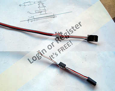
▲
⟩⟩
BOATSHED
Martin555
RNinMunich
|
|
💬 Re: Fire Monitors Part 2
5 years ago by 🇬🇧 Rookysailor (
Commodore)✧ 64 Views · 2 Likes
Flag
Great idea Graham, another option for your problem of servo travel distance, is a servo morph from component shop, have given a link.🙂
▲
⟩⟩
BOATSHED
Martin555
|

|
💬 Re: Fire Monitors Part 2
5 years ago by 🇬🇧 mturpin013 (
Admiral)✧ 63 Views · 0 Likes
Flag
Really nice work Graham, does the copper water inlet pipe below the cabin roof rotate?
If as I think it does, then having 270 deg really isn’t required or appropriate as the pipe will get twisted and hopefully you will be only spraying water over the side (not back and front as guns do) and only having squrting power on one side of the boat will not really be noticeable. ▲
⟩⟩
No likes yet
This member will receive 1 point for every like received |
|
💬 Re: Fire Monitors Part 2
5 years ago by 🇩🇪 RNinMunich (
Fleet Admiral)✧ 64 Views · 2 Likes
Flag
That's one way Martin 👍
For the X and Y guns on my destroyer I simply added 3 to 1 reduction gears, to the servo directly connected to X gun, giving ca 270° end to end. Y gun was then driven 1 to 1 by pulley drive. The green pulley belt I buy by the metre, cut to length to keep some tension on, and just glue with super glue. Still holding after 25 years or so🤞 Under deck the mountings are ball races with 8mm OD ally tube pressed in. The tubes transmit the rotation up to the guns. Above deck the gun mounts are the track cases of decades old potentiometers, as once used for volume controls etc. The guns and guards are all wood with a wooden spigot flattened on one side. The ally tube was also appropriately flattened on one side to key the 'plug in' guns. X Gun Capt. now has to be careful not to blast the bridge off 😮 "Cor, blimey! WHO threw that?" Strangely the Captain has given him special privileges on board😉 Doug 😎 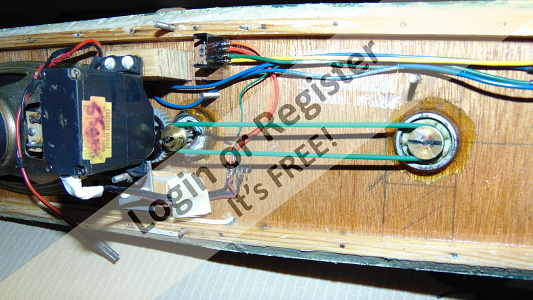
▲
⟩⟩
BOATSHED
Martin555
|
|
💬 Re: Fire Monitors Part 2
5 years ago by 🇬🇧 Martin555 (
Fleet Admiral)✧ 65 Views · 2 Likes
Flag
Hi Graham,
you have done a superb job. looking forward to seeing it in operation. There is another way to get more rotation, and that is to modify the servo to rotate continuously and then add some limit switches. That is what i had done to the main gun on my HMS Cottesmore. martin555. ▲
⟩⟩
BOATSHED
RNinMunich
|
|
💬 Re: Fire Monitors Part 2
5 years ago by 🇩🇪 RNinMunich (
Fleet Admiral)✧ 64 Views · 2 Likes
Flag
Very nice Graham👍
Well thought out. Which pulse stretcher did you use? Sure I've seen one somewhere that claims 270°. Maybe you need to adjust the end stops in the servo? Doug 😎 ▲
⟩⟩
BOATSHED
Martin555
|
📝 Fire Monitors Part 3
5 years ago by 🇬🇧 Graham93 ( Vice Admiral)
Vice Admiral)✧ 68 Views · 8 Likes · 10 Comments
Flag
💬 Add Comment
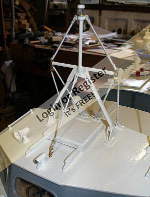
I have finally fitted the monitors onto the boat.
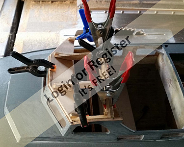
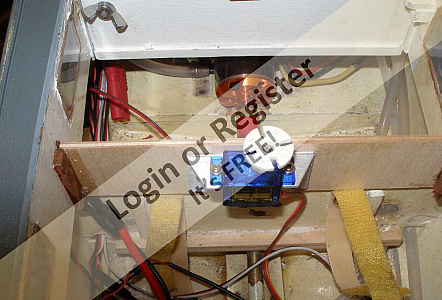
Servo mounts were made from aluminium angle. The position of the mounting hole in the forward cabin roof for the 8mm tube (see Part 2) was calculated based on the distance between the servo shaft and the mounting face of the aluminium servo mount plus a couple of mm. for adjustment. This dimension gave the distance of the hole from the bulkhead (CF3) on which the servo was to be mounted. The 8mm tube was glued into roof hole using epoxy. Once the epoxy was set the roof was put in position and a 7mm tube with wet paint on the end was slid down the 8mm mount to make contact with a temporary wooden block attached with double sided tape to the CF3 bulkhead below. The wet paint left a circular mark on the wooden block indicating where the servo should be positioned so that it's shaft would align with the fire monitor rotating column in the roof. The extra couple of mm. allowed for a spacer of suitable thickness to be made and fitted under the servo mount to achieve the correct alignment. The distance between the top of the 8mm tube and the wooden block was also measured allowing the required height of the servo mount to be calculated.
The same process was followed for the second fire monitor mounted on the engine room roof. In this case, the bulkhead (B4) had to be extended vertically to position the servo close enough to the roof. The servo mounts, and the new timber within the boat still need to be painted.
I had intended to use the crucifix servo arm to drive the rotating column, as can be seen in one of the photos. Whilst this worked OK, it was difficult to fit the roof and get the four pins at the bottom of the rotating column to engage in the holes in the servo arm. To make this easier the servo arms were adapted by adding a disc of 2mm plasticard with radial slots to engage with the drive pins. This has made fitting each roof easier.
The servo stretcher worked well, giving 180 degrees of rotation. However, once I saw it in operation, I decided it would be better to increase this to around 240 degrees as I had suspected. As stretching the drive pulse even further would not give more rotation I decided to try modifying the servos instead. This turned out to be easier than expected. Each servo was dismantled and two 3K resistors were added, one to each end of the feedback pot. The value was determined by trial and error. There was plenty of room to accomodate 1/8W resistors within the servo case. You can just see them in the photos. The servos now give the desired rotation without the need for the pulse stretchers.
I was hoping to include the plumbing details in this post, but I have had a few issues making this work acceptably, so I have had to go back to the drawing board and now have a few more bits and pieces to make. More to follow.....
▲
⟩⟩
BOATSHED
MouldBuilder
Commodore-H
jbkiwi
robbob
Martin555
RNinMunich
Rookysailor
|
💬 Re: Fire Monitors Part 3
5 years ago by 🇬🇧 Graham93 (
Vice Admiral)✧ 64 Views · 1 Like
Flag
Doug,
I also find I have lots of very low resistor values that I’m unlikely to ever use. At least with those I can put them in series to make a useful value, and the calculation is much easier🤣 Graham93 ▲
⟩⟩
BOATSHED
|
|
Login To
Remove Ads 💬 Re: Fire Monitors Part 3
5 years ago by 🇩🇪 RNinMunich (
Fleet Admiral)✧ 64 Views · 1 Like
Flag
Agreed on all counts Graham👍
I also bought a box selection of the E24s. Now have hundreds of zig MegOhm values I'll probably never use🤔 S'pose I could stack a thousand or so in parallel to make a more useful value 😁 Keep up the great work and tutorial. Good stuff. Cheers, Doug 😎 ▲
⟩⟩
BOATSHED
|
|
💬 Re: Fire Monitors Part 3
5 years ago by 🇬🇧 mturpin013 (
Admiral)✧ 64 Views · 1 Like
Flag
Fantastic ! both of you are always so helpfull, not only to me but others on the site.
thanks again ▲
⟩⟩
BOATSHED
|
|
💬 Re: Fire Monitors Part 3
5 years ago by 🇬🇧 Graham93 (
Vice Admiral)✧ 65 Views · 3 Likes
Flag
Thanks Doug, I got a bit carried away with the technical bit and missed Michael's request for resistor colour codes. My only excuse is it was late last night 😉
3k isn't standard in the common E12 series of resistor values, but it is standard in the E24 series. I recently bought a pack of 1000 mixed E24 values in 1/8W size quite cheaply from Ebay as I needed physically smaller resistors for model use. They are so small it is difficult to see the colour code printed on them, but fortunately the carrier strips are printed with the values. A good ohm meter also helps.😁 Graham93 
▲
⟩⟩
BOATSHED
RNinMunich
Martin555
|
|
💬 Re: Fire Monitors Part 3
5 years ago by 🇩🇪 RNinMunich (
Fleet Admiral)✧ 64 Views · 2 Likes
Flag
Hi Michael,
"what the resisters were (colour code)" The attached chart might help you identify resistors in future.😉 Graham used 3KΩ (3000Ohms) which would be Orange, Black, Red signifying 30 x 100=3000. But 3K is not a 'standard' (easy to get value), the nearest would be 3.3K (3300Ohms), which is coded Orange, Orange, Red. In the more common 4 band system. Or Orange, Orange, Black, Brown (330x10) in the more 'exotic' 5 band system. The last band is the tolerance band. Usually 1% or 5% these days for for the standard values. Happy monitoring,😊 Cheers, Doug 😎 PS Here's a resistor calculator which can help👍 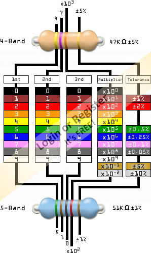
▲
⟩⟩
BOATSHED
Martin555
|

|
💬 Re: Fire Monitors Part 3
5 years ago by 🇬🇧 Graham93 (
Vice Admiral)✧ 65 Views · 3 Likes
Flag
Mike,
The servos I have used are TowerPro SG90s, but I expect the modification would work on any analogue servo, although the resistor values may need to change. Servos have a feedback potentiometer attached to the servo output shaft. This pot feeds a variable voltage into the servo electronics based on the output shaft position. For the SG90 servo this voltage is 1.0V when the control stick is at its minimum setting (= 1mSec pulse width) and 2.35V when the control stick is at its maximum setting (= 2.0mSec pulse width). The servo (and feedback pot) rotate about 100 degrees between these two settings. Before modification the pot, which is capable of around 250 degrees rotation, has a total voltage of 3.3v across the ends of the track. Thus 250 degrees of rotation would equate to 3.3V and hence 100 degrees equates to the 1.35V range given above (2.35V-1V). By adding resistors to each end of the potentiometer track, we can reduce the voltage across the track such that the 250 degrees of available rotation equates to a voltage change of only 1.35V. This way the servo has to rotate much further to provide the electronics with the 1V to 2.35V input it is expecting. Adding the resistors involved dismantling the servo, cutting the outer two leads to the feedback pot and fitting the 3K resistors between the cut ends. Hope the attached sketches, together with the photos previously posted help. Graham93 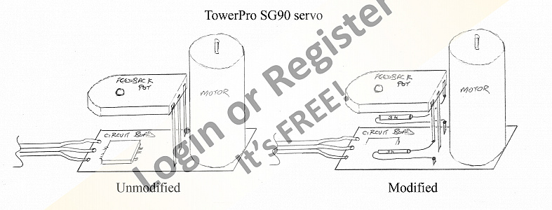

▲
⟩⟩
BOATSHED
Martin555
RNinMunich
|
|
💬 Re: Fire Monitors Part 3
5 years ago by 🇬🇧 mturpin013 (
Admiral)✧ 64 Views · 2 Likes
Flag
Really good result Graham, can you give more detail on the type of servo and what the resisters were (colour code) and where they go (Im non electronics) so could do with basic explanation
Thanks Ps I have just about got my system working, a different take on the solution ▲
⟩⟩
BOATSHED
Martin555
|
|
💬 Re: Fire Monitors Part 3
5 years ago by 🇳🇿 jbkiwi (
Fleet Admiral)✧ 64 Views · 2 Likes
Flag
Nice bit of work Graham, like the monitor drive idea! simple and effective. Nice servo mod as well.
▲
⟩⟩
BOATSHED
Martin555
|
|
💬 Re: Fire Monitors Part 3
5 years ago by 🇬🇧 Martin555 (
Fleet Admiral)✧ 64 Views · 2 Likes
Flag
Nice work Graham,
As soon as you start getting bits and pieces moving it gives you that extra bit of motivation. Well done. Martin555. ▲
⟩⟩
BOATSHED
Rookysailor
|
|
💬 Re: Fire Monitors Part 3
5 years ago by 🇬🇧 Rookysailor (
Commodore)✧ 64 Views · 2 Likes
Flag
Nice simple uncomplicated idea Graham, love your idea of using paint on the tube end to find the place to fix, will definitely be using that idea.😳
Cheers, Peter (Rooky) ▲
⟩⟩
BOATSHED
Martin555
|
📝 Fire Monitors Part 4
5 years ago by 🇬🇧 Graham93 ( Vice Admiral)
Vice Admiral)✧ 67 Views · 8 Likes · 13 Comments
Flag
💬 Add Comment
The boat has a water cooled ESC and engine mount. These are fed from a scoop behind the prop. The water circulates through the ESC and engine mount and then out through the exhaust ports on the transom. The first attempt at plumbing in the monitors was to simply tap into this cooling circuit, add a filter and pump and feed the pumped water to the monitors. This didn't work too well.
With the pump running the monitors worked well, but water was sucked backwards out of the cooling circuit, drawing air in through the exhaust ports until the pump was sucking on air and the monitors stopped working. I had sort of expected this might occur so I had a non return valve available ready to fit in circuit just before the exhaust ports to prevent this reverse flow. I had hoped I would not need to fit it as I am concerned that the extra flow resistance it will cause will reduce the effectiveness of the cooling circuit. The second, unexpected problem with this simple approach was that, with the pump off, there was enough water pressure in the cooling circuit that the monitors continued to dribble water onto the cabin roof from where it drained into the hull. Adding the non return valve in the cooling circuit would only serve to make this problem worse owing to the increased pressure in the circuit. The last thing I want is for the boat to slowly fill with water, drenching all the electrics and gradually sinking so this dribble needs to be stopped.
After some thought, I decided that a diverter valve could be the solution. This would route the water either to the pump and monitors, or to the cooling circuit. I reasoned that I would not want the monitors working while the drive motor was running at high speed and so can afford to switch off the cooling circuit while the monitors are operating. I had an interesting few hours making a servo driven cam mechanism which at one end of it's travel would squash the silicone tube to the cooling circuit while allowing flow to the pump and monitors. At the other end it would cut off the water to the pump, and enable the cooling circuit. The servo would be driven by the same channel as the RCswitch that turns the pump on/off. Great idea, but it didn't work 🤔 The servo doesn't have enough power to turn the cam and squash the tubes and simply stalls. I need to try thinner tubes, or a more powerful servo, or something? Any helpful suggestions welcome...
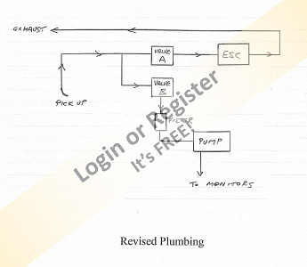
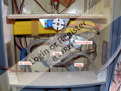
Throughout the summer I have tried to keep the boat sailable for the local club sessions on a Wednesday afternoon. Not wanting to have to keep it in dry dock for an extended period while solving this issue I tried a different approach. I had available two solenoid valves so these were pressed into service as shown in the sketch. An RCswitch was constructed so that, with the pump on, valve A is closed and valve B is open. This routes the water flow to the pump and monitors. With the pump off, valve A is open and valve B is closed, routing the water to the cooling circuit. This works!
In the video (my first ever on YouTube) you can see how water flows from the exhaust ports when the monitors are off. I don't have a test tank at home so water is fed into the water scoop connection using a small aquarium pump. Now I just need jbkiwi to solve the smoker challenge so that I can add some smoke 😁


With the pump running the monitors worked well, but water was sucked backwards out of the cooling circuit, drawing air in through the exhaust ports until the pump was sucking on air and the monitors stopped working. I had sort of expected this might occur so I had a non return valve available ready to fit in circuit just before the exhaust ports to prevent this reverse flow. I had hoped I would not need to fit it as I am concerned that the extra flow resistance it will cause will reduce the effectiveness of the cooling circuit. The second, unexpected problem with this simple approach was that, with the pump off, there was enough water pressure in the cooling circuit that the monitors continued to dribble water onto the cabin roof from where it drained into the hull. Adding the non return valve in the cooling circuit would only serve to make this problem worse owing to the increased pressure in the circuit. The last thing I want is for the boat to slowly fill with water, drenching all the electrics and gradually sinking so this dribble needs to be stopped.
After some thought, I decided that a diverter valve could be the solution. This would route the water either to the pump and monitors, or to the cooling circuit. I reasoned that I would not want the monitors working while the drive motor was running at high speed and so can afford to switch off the cooling circuit while the monitors are operating. I had an interesting few hours making a servo driven cam mechanism which at one end of it's travel would squash the silicone tube to the cooling circuit while allowing flow to the pump and monitors. At the other end it would cut off the water to the pump, and enable the cooling circuit. The servo would be driven by the same channel as the RCswitch that turns the pump on/off. Great idea, but it didn't work 🤔 The servo doesn't have enough power to turn the cam and squash the tubes and simply stalls. I need to try thinner tubes, or a more powerful servo, or something? Any helpful suggestions welcome...
Throughout the summer I have tried to keep the boat sailable for the local club sessions on a Wednesday afternoon. Not wanting to have to keep it in dry dock for an extended period while solving this issue I tried a different approach. I had available two solenoid valves so these were pressed into service as shown in the sketch. An RCswitch was constructed so that, with the pump on, valve A is closed and valve B is open. This routes the water flow to the pump and monitors. With the pump off, valve A is open and valve B is closed, routing the water to the cooling circuit. This works!
In the video (my first ever on YouTube) you can see how water flows from the exhaust ports when the monitors are off. I don't have a test tank at home so water is fed into the water scoop connection using a small aquarium pump. Now I just need jbkiwi to solve the smoker challenge so that I can add some smoke 😁
▲
⟩⟩
dave976
BOATSHED
robbob
mturpin013
MouldBuilder
jbkiwi
Martin555
RNinMunich
|
💬 Re: Fire Monitors Part 4
5 years ago by 🇭🇺 MouldBuilder (
Vice Admiral)✧ 64 Views · 1 Like
Flag
Hi Doug.
I am using a 3s lipo. I was only making a comment about 7.4v. I have now purchased two 6volt valves the same design as before. ▲
⟩⟩
BOATSHED
|
|
Login To
Remove Ads 💬 Re: Fire Monitors Part 4
5 years ago by 🇩🇪 RNinMunich (
Fleet Admiral)✧ 65 Views · 3 Likes
Flag
Hi Peter,
"I cannot get mine to work without applying around 10v. I am a little more optimistic of my setup if they can trigger at 7.4v." But you did mention that the solenoids were rated for 12V, 160mA. I also checked them at your source. So considering the voltage losses mentioned in my post just now in your Gato blog, due to the ESC and rectifier, you do not have a cat in hell's chance of operating that valve when the pump is reversed. Get rid of the rectifier (not needed) and use an ESC and/or TX setting to raise the max reverse voltage to the same as forward voltage, i.e. 100%. Battery must be 12V. A 3S Lipo should cut it as well. At 7.4V you don't even need to waste time trying, not with that valve anyway. Look for a 6V valve. Sorry if that sounds a bit blunt but I would have thought that it was pretty obvious that for a solenoid rated at 12V applying 7.4V will only create about 60% of the magnetic field strength needed to overcome the valve return springs. So it would never open. Doug. ▲
⟩⟩
BOATSHED
MouldBuilder
Martin555
|
|
💬 Re: Fire Monitors Part 4
5 years ago by 🇬🇧 mturpin013 (
Admiral)✧ 64 Views · 2 Likes
Flag
Really very interesting article, There are more things to consider than you first think. Its been a help to me as Im just doing this job at the moment.
▲
⟩⟩
BOATSHED
Martin555
|
|
💬 Re: Fire Monitors Part 4
5 years ago by 🇬🇧 Graham93 (
Vice Admiral)✧ 65 Views · 3 Likes
Flag
Hi JB,
Re: How about using something like these remote switches which I use on my HSL and ST to turn pumps and lights etc on/off. Yes, that would work but I should have explained the issue clearer. With the pump plumbed on the feed from the pickup as you suggested, the pump will need to run both when the monitors are in use and for cooling the motor/ESC. With they way I have it plumbed currently, the pump doesn’t need to run to cool the motor/ESC. If I do find I need to change it round, I’ll probably put a remote switch together to connect to the throttle channel and the solenoid (fire monitor) channel. The switch could then turn the pump on when needed for either function. Graham93 ▲
⟩⟩
BOATSHED
RNinMunich
Martin555
|
|
💬 Re: Fire Monitors Part 4
5 years ago by 🇬🇧 Graham93 (
Vice Admiral)✧ 65 Views · 3 Likes
Flag
Hi Peter,
No, there isn’t any back pressure on the valves. They seem to work OK at around 7.5v but I don’t have much run time with them yet to know if they will be reliable at this voltage. Graham93 ▲
⟩⟩
BOATSHED
MouldBuilder
Martin555
|
|
💬 Re: Fire Monitors Part 4
5 years ago by 🇳🇿 jbkiwi (
Fleet Admiral)✧ 64 Views · 2 Likes
Flag
Re- Yes, I could change the plumbing round as you suggest
How about using something like these remote switches which I use on my HSL and ST to turn pumps and lights etc on/off. As long as you have a spare switch (or rotary - I use the rotary on my HK 6ch to turn on the lights) You could also switch it in the TX program to work with the motor. In the ST I have one switching the pump and ESC fans and one for lights. I only use a 2s 1800MAh LiPo to drive my pump in the ST, and it will run for more than an hour, and the battery will only get down to 3.8/cell, (from 4.1) - a 2200MAh would last forever. When I tested my pump, it was only drawing about 1.25A loaded. Do you know what your particular pump draws? You would not be running the monitors constantly but you could always put another small pump in the motor line and run it constantly as I do, and do away with the solenoids (it will act as a non return valve as well ) and if needed you could switch it off remotely. JB 
▲
⟩⟩
BOATSHED
Martin555
|
|
💬 Re: Fire Monitors Part 4
5 years ago by 🇭🇺 MouldBuilder (
Vice Admiral)✧ 64 Views · 2 Likes
Flag
Very impressive Graham. I am interested in your comment regarding the solenoid valves. I see that they are 12v; do they have exposure to any back pressure as I cannot get mine to work without applying around 10v. I am a little more optimistic of my setup if they can trigger at 7.4v.
Thanks. Peter. ▲
⟩⟩
BOATSHED
Martin555
|
|
💬 Re: Fire Monitors Part 4
5 years ago by 🇬🇧 Graham93 (
Vice Admiral)✧ 65 Views · 5 Likes
Flag
JB,
Yes, I could change the plumbing round as you suggest. The downside is the pump would have to run continuously. The present arrangement only needs the pump running when the monitors are in use. However, when it comes to smoking exhaust, maybe I’ll need it plumbed that way Doug, The solenoid valves were sourced from a box in my workshop, which is now empty, so there is no point providing a weblink to that 🤣. However as the box is empty, I did order two more earlier today from eBay for smoker experiments. These are identical to the ones I used for the monitors and look very similar to the ones JB has found. They are rated 12v but seem to work quite happily on a 2S LiPo. Draw less current that way which will help with battery duration. Whilst it works well in practice, I’m not too happy with the dual solenoid solution from a current draw point of view. One solenoid is always activated, so there is a constant current drain. The servo driven cam solution would have had minimal current drain, shame it didn’t work 🤔 Graham93 ▲
⟩⟩
BOATSHED
mturpin013
Martin555
jbkiwi
MouldBuilder
|

|
💬 Re: Fire Monitors Part 4
5 years ago by 🇳🇿 jbkiwi (
Fleet Admiral)✧ 64 Views · 3 Likes
Flag
Re - Where did you sources the valves Graham?
Hi Doug, I've just found some on Ali Express while looking for air pumps, check these puppies out😁 JB 
▲
⟩⟩
BOATSHED
mturpin013
Martin555
|
|
💬 Re: Fire Monitors Part 4
5 years ago by 🇳🇿 jbkiwi (
Fleet Admiral)✧ 64 Views · 2 Likes
Flag
Re - The boat has a water cooled ESC and engine mount.
Hi Graham, boat's looking great, monitors brilliant! Had a thought about the water system and was wondering if you could do the layout in a slightly different way. With the pump where it is in the drawing, it might have a harder time sucking the water through the pipe and valve than if it were nearer the pickup, (it would be pushing more than sucking, - maybe less strain on the pump). Also giving you water from the exhausts when stationary (unless you are intending a second pump for that) Suggestion pic of layout JB 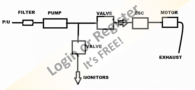
▲
⟩⟩
BOATSHED
Martin555
|
|
💬 Re: Fire Monitors Part 4
5 years ago by 🇩🇪 RNinMunich (
Fleet Admiral)✧ 64 Views · 2 Likes
Flag
Where did you sources the valves Graham?
Can you post a Web Link please? And what voltage are they? (Questions questions questions!!😁) I think there are several members who'd like to know that. Cheers, Doug 😎 ▲
⟩⟩
BOATSHED
Martin555
|
|
Login To
Remove Ads 💬 Re: Fire Monitors Part 4
5 years ago by 🇬🇧 Graham93 (
Vice Admiral)✧ 66 Views · 4 Likes
Flag
Hi Martin,
The cooling isn’t pumped. There is enough flow round the circuit just from the motion of the boat and the pressure from the prop. At least there was until I fitted the valve. Haven’t had chance to test it on the lake since I fitted that. If necessary, I could change the plumbing so that the pump is in the direct line from the water pickup and runs all the time. That would increase flow through the cooling circuit, and the valves could still be used to switch the flow between cooling and monitors. Graham93 ▲
⟩⟩
BOATSHED
MouldBuilder
Martin555
RNinMunich
|
|
💬 Re: Fire Monitors Part 4
5 years ago by 🇬🇧 Martin555 (
Fleet Admiral)✧ 64 Views · 1 Like
Flag
Hi Graham,
Is there any particular reason that you are only using one pump for cooling and monitors ? Martin555. ▲
⟩⟩
BOATSHED
|
📝 Exhaust Smoker
5 years ago by 🇬🇧 Graham93 ( Vice Admiral)
Vice Admiral)✧ 67 Views · 11 Likes · 14 Comments
Flag
💬 Add Comment
Following several weeks experimenting, and lots of discussion with jbkiwi, the exhaust smoker is now installed in the Crash Tender.
The heart of the device is an e-cig tank and coil. This was adapted with an acrylic end piece to allow connection of power and air. The 2ml capacity of the e-cig is a bit limiting so an expansion tank made from acrylic tube was added to give a fluid capacity of around 10ml. The smoker fluid is 75% vegetable glycerine.
The coil in the e-cig is designed to work from a single cell LiPo battery. A power converter drops the voltage from the boat's 2S battery down to 3.5V with a claimed efficiency of 98%. This voltage is adjustable which allows control of the amount of smoke produced.
Forced air is provided by a small diaphragm pump salvaged from a defunct blood pressure monitor. This pushes air through the e-cig. The resulting smoke is fed into the cooling water line between the ESC and the exhaust ports.
As the smoker is most effective simulating the engine 'ticking over' a water pump is used to create some water flow when the main propulsion motor isn't running. This adds more realism to the effect.
An electronic controller based on PIC microchips connects to the throttle channel and pulses the air pump at a rate determined by the throttle setting. It also runs the water pump at a slow speed, and controls the power to the smoke generator coil. If the throttle is held at maximum for a couple of seconds, the smoker pumps and coil are switched off to save on battery consumption. With the throttle at idle, a quick blip forward on the throttle will start the smoker again. Power consumption is around 0.7A on a 2S LiPo.
The two pumps are mounted below the footwell floor and the smoke generator is fixed to the bulkhead at the rear of the engine room.
My thanks go to jbkiwi for his encouragement and suggestions during the development of this feature.
Graham93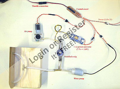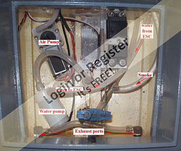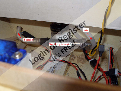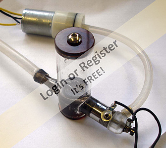
▲
⟩⟩
Black Shoe
GaryLC
Madwelshman
BOATSHED
MouldBuilder
jbkiwi
Rookysailor
mturpin013
Back in the Groove
robbob
Martin555
|
💬 Re: Exhaust Smoker
4 years ago by 🇳🇿 jbkiwi (
Fleet Admiral)✧ 64 Views · 2 Likes
Flag
Good chance this sort of thing is what's driving the sound in these modules I have. Wonder if it would be possible to download a new sound by using another SD card (if my units do have that type of system,- haven't pulled one apart so have no idea what's inside.) Too hard to contact the manufacturer,- they say if you send them a sound file they will email you a file to upload to the unit, but my last query was unanswered (no email back)
Not to worry, the sounds I have work ok, and there are probably 0 people in the country who know what a Napier Sea Lion engine sounds like, (in the HSL for eg). When it comes down to it, unless you are trying to score points in a scale competition, who would ever know (or care) what engine a boat had in it (except perhaps you). If it sounds close enough, it will still impress people. It was quite funny when I demo'd the diesel sounds I was first using in the HSL, to the present owner of the original 100% HSL, as he thought that it sounded just like the engine he had fitted to it (GM 8v-92- previously 2x GM 671). At least 1 person in NZ liked it! JB ▲
⟩⟩
dave976
BOATSHED
|
|
Login To
Remove Ads 💬 Re: Exhaust Smoker
4 years ago by 🇬🇧 Graham93 (
Vice Admiral)✧ 64 Views · 3 Likes
Flag
Hi JB,
I was thinking of a simple artificial sound generator as that isn’t too difficult to put together. I think it would just be a bit more software in the revised controller I’m putting together. However, I’ve just been browsing my favourite on-line store and found this. There also seem to be plenty of sound files available on the www to download. Would undoubtedly sound better, but unfortunately it will have to go on my ever increasing ‘to do’ list😉 Graham93 ▲
⟩⟩
dave976
BOATSHED
jbkiwi
|

|
💬 Re: Exhaust Smoker
5 years ago by 🇳🇿 jbkiwi (
Fleet Admiral)✧ 64 Views · 2 Likes
Flag
Hi Graham, I think the pumps I am waiting for are the the same as you've shown here (round micro air pump), saw a diapragm pump somewhere but can't remember what site (Ali Express I think) There are some very flash ones but they are above $50 for the basic one (might be a mini piston pump I think) American lab equipment co from memory.
Re sounds, the ones I use are car versions by GT Power which have around 50 car sounds loaded, and a few make good boat sounds. Unfortunately they don't have sounds for Napier Sea lions or Rover Meteorite V8 fireboat engines (but there is a V8 sound which I use in the ST and MTB and another sound in the HSL which are quite suitable. There are diesel sounds good for tugs etc and various others. The start up and shut down is a cool feature. They are about the only thing I've seen that's half decent, as they are actual sounds, not artificial. I think they run off an internal SD card and the sounds (from start up to full revs) are split into lots of small WAV files, and when the throttle stick is at a static position, the sound in that file keeps looping till you move the stick, (quite subtle on a lot of the sounds) You can hear them in the ST vids. I was thinking, if someone was clever they might be able to get the proper sounds and write a new file, (you can plug the unit into your computer and open the sound files as well as some adjustable features). probably have to figure out how the files are linked to the player in the unit and how the TX signals them to play ? JB ▲
⟩⟩
dave976
BOATSHED
|
|
💬 Re: Exhaust Smoker
5 years ago by 🇬🇧 Graham93 (
Vice Admiral)✧ 64 Views · 3 Likes
Flag
Hi JB,
I've tried a couple of air pumps and prefer the one salvaged from the blood pressure monitor as it is a diaphragm pump which seems to give it more grunt, despite running on a lower voltage. It is also smaller than the other one I tried so it was easier to fit under the footwell floor. Your original posts got me thinking about how to solve the challenge of making something that gives a realistic effect. I love a challenge like that 😀. Now you have suggested it needs sound to go with it. Just when I thought we were nearly there 🙄. Something else to think about... Graham93 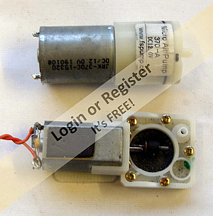
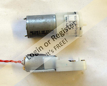
▲
⟩⟩
dave976
BOATSHED
jbkiwi
|
|
💬 Re: Exhaust Smoker
5 years ago by 🇳🇿 jbkiwi (
Fleet Admiral)✧ 64 Views · 2 Likes
Flag
Re- following several weeks experimenting,
I was going to ask what pump you had Graham but you have answered it here. Seems to work quite well, not sure how mine will go (if they ever arrive) but there are a number of air pumps on line to try. Need something with a bit of grunt to it. I think this little project has been a great example of Kiwi/Anglo cooperation as we have both swapped ideas back and forth to get this result. Graham has refined the electronics and done a great job and I'm pleased that he has taken an interest in my original simple idea, and with his electronics knowledge made it pretty flash. With the greater model boat interest in the UK, I'm sure it will be seen on more models yet and is a device which can be easily adapted to any model - tugs, PT boats, barges etc, - with or without water. The best thing is it can be made very cheaply as against the price of current marine smoke machines. JB ▲
⟩⟩
dave976
BOATSHED
|
|
💬 Re: Exhaust Smoker
5 years ago by 🇳🇿 jbkiwi (
Fleet Admiral)✧ 64 Views · 2 Likes
Flag
Re -A few short video clips of the smoking Crash Tender
Don't know how I missed these Graham, that looks excellent, really should get a few comments at a club meet! Pity I've got no one here to impress other than a few passers by. I'm still trying to make mine small enough to fit in the ST but as previously mentioned the low floor makes it difficult. You need some engine sounds to go with it now! JB ▲
⟩⟩
dave976
BOATSHED
|
|
💬 Re: Exhaust Smoker
5 years ago by 🇬🇧 Rookysailor (
Commodore)✧ 64 Views · 1 Like
Flag
What a fabulous effect for a boat, the mind boggles
how you and jb, managed to fulfill the idea, just pure talent👍 Cheers, Pete btw Video is excellent, even in the rain! ▲
⟩⟩
BOATSHED
|
|
💬 Re: Exhaust Smoker
5 years ago by 🇬🇧 Graham93 (
Vice Admiral)✧ 64 Views · 3 Likes
Flag
Hi Michael,
Thanks, glad you like it.👍 Re: Is the electronic controller based on PIC microchips a commercially available item? The controller is my design based on three baseline PIC microchips. Not the most elegant of designs, as this could all be implemented in one mid range PIC with a bit more effort, but it was quick to do this way, and I have a stock of the baseline parts. PIC1 acts as a simple RCswitch monitoring the throttle channel to turn the smoker on/off. PIC2 provides the smoke pulses by turning the air pump on/off at a rate determined by the throttle channel. PIC3 implements two motor speed controllers, one for the water pump, and one for the air pump. This latter speed controller is modulated by the on/off pulses from PIC2. The circuit board shows the three PICs. On the underside of the board there are three surface mount power FETs to drive the smoker coil and the two pumps. I'm happy to share more details on my current implementation of this, but it is not very configurable/transferrable unless you have experience with PICs and the necessary tools. For example, following the trial on the lake yesterday, I think it would work better if the water pump was running a bit faster. To make that happen I have to change some values in the software, and then reprogram the appropriate PIC. It was just easier to put together this way, but its not very practical on the lake.🙄 I have it in mind to redevelop the software on a better PIC and to add some buttons on the circuit board so that various parameters could be adjusted without having to reprogram the PICs. It will be an interesting challenge, but will take a little while as I'll have to fit it in around everything else 😉. Graham93 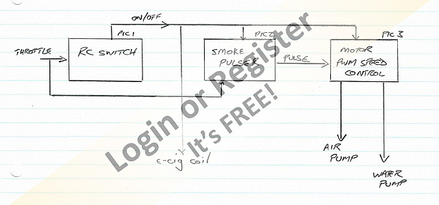
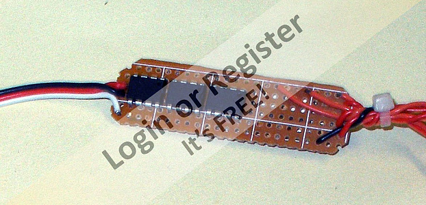
▲
⟩⟩
dave976
BOATSHED
mturpin013
|
|
💬 Re: Exhaust Smoker
5 years ago by 🇬🇧 Martin555 (
Fleet Admiral)✧ 64 Views · 1 Like
Flag
Spot on Graham.
Excellent and just as i pictured it. Well done. Martin555. ▲
⟩⟩
BOATSHED
|
|
💬 Re: Exhaust Smoker
5 years ago by 🇬🇧 marky (
Commodore)✧ 64 Views · 2 Likes
Flag
Looks great ,videos are great.
▲
⟩⟩
BOATSHED
Martin555
|
|
💬 Re: Exhaust Smoker
5 years ago by 🇬🇧 mturpin013 (
Admiral)✧ 65 Views · 3 Likes
Flag
Hi Graham what a wonderful result, congratulations.
Once again someone has set the bar at a really high standard, one which I have to try and reach as I'm just about to start on this part of my build. (some reasearch needed me thinks!) Is the electronic controller based on PIC microchips a commercially available item or as I think one of your own design? As mechanical engineer, any chance of a wiring diagram, happy to pay? ▲
⟩⟩
BOATSHED
Martin555
robbob
|
|
Login To
Remove Ads 💬 Re: Exhaust Smoker
5 years ago by 🇬🇧 Graham93 (
Vice Admiral)✧ 65 Views · 6 Likes
Flag
Rob, Martin,
Thanks for the positive comments. A few short video clips of the smoking Crash Tender on the lake this afternoon. Weather conditions were far from ideal. No on-lookers to ask questions 🤣. Weatherwise, it felt more like I should be sailing an icebreaker😁 Graham93 ▲
⟩⟩
dave976
BOATSHED
jbkiwi
Martin555
robbob
mturpin013
|
|
💬 Re: Exhaust Smoker
5 years ago by 🇬🇧 Martin555 (
Fleet Admiral)✧ 64 Views · 3 Likes
Flag
Hi Graham,
All of you'r experiments have really paid off. That is fantastic. I can already see the faces of the onlookers as she is just gently moves away from the jetty water spitting out and the exhaust smoke gently puffing. I wonder how many times you will get asked how did you manage to do that! Excellent work. Well done. Martin555. ▲
⟩⟩
BOATSHED
mturpin013
Graham93
|
|
💬 Re: Exhaust Smoker
5 years ago by 🇬🇧 robbob (
Admiral)✧ 64 Views · 4 Likes
Flag
Hi Graham.
Very nicely engineered👍 the video of the result of your efforts clearly shows that it works and is most realistic. Combined with the operational fire monitors the plumbing and electrical arrangements for these features are ingenious. Congratulations. Robbob. ▲
⟩⟩
BOATSHED
mturpin013
Graham93
Martin555
|


Login To
Remove Ads
Remove Ads