Join Us On Social Media!

|

|

|
Download The App!
Login To
Remove Ads
Remove Ads
Login To
Remove Ads
Remove Ads
Model Boats Website
SLEC Harbour Pilots Boat by Robbob
55 Posts · 29 Followers · 708 Photos · 678 Likes
Began 4 years ago by
 United Kingdom
Follow This Thread
Not currently following
> Click to follow
> Click to follow
Latest Post 3 years ago by
| Oldest posts shown first (Show Newest First) | (Print Booklet) |
📝 SLEC Harbour Pilots Boat by Robbob
4 years ago by 🇬🇧 robbob ( Admiral)
Admiral)✧ 94 Views · 12 Likes · 6 Comments
Flag
💬 Add Comment
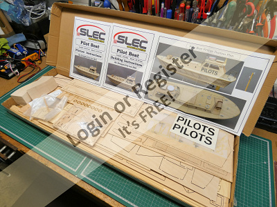
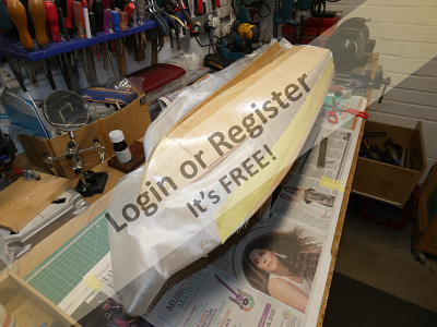
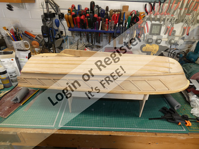
It’s been a while since I built my last model boat, a Thames River Police Launch and prior to that my RAF Crash Rescue Tender and I thought I’d better get something on the go pretty soon or I’ll have nothing new to show at the club exhibition in September.
While I was visiting the Warwick International Model Boat Show in November last year I spotted a new model by SLEC of a Harbour Pilots Boat, due for release in Spring 2020.
A quick ‘phone call to them confirmed that it was now available and so I decided to buy the kit and start building it to keep me occupied during the enforced isolation we all find ourselves in at the present.
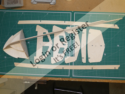
The kit arrived the following day, very safely packaged in a strong carton, and after opening the box and quickly checking the contents I took out the supplied Building Instruction and Picture Instruction manuals and studied them both at length to familiarise myself with the construction sequence.
Anyone that is familiar with the old Aerokits/Keil Kraft model boats will recognise their characteristic ‘egg crate’ method of construction and this model is a re-working of one such design by Ian Hull for SLEC.
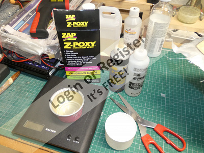
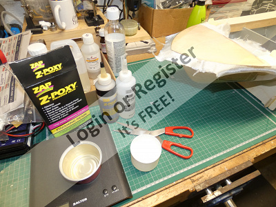
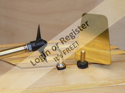
Fortunately I have all the required tools, adhesives and other materials in the workshop including a 10” propshaft and 40mm 2 blade prop that I bought in error for a previous model and so I can make an immediate start. I’ll still need to buy in a receiver, servo, rudder, brushless motor and speed controller and a couple of LiPo batteries at some point but I certainly have all I need to make a start on the build.
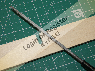
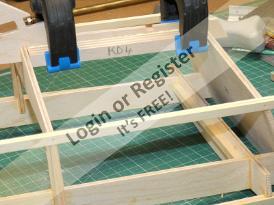
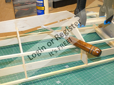
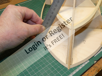
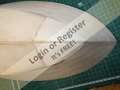
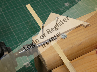
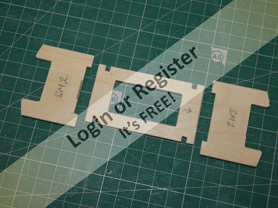
All of the plywood parts are CNC router or laser cut and many of the parts lock firmly together with tabs and slots that are already quite a good fit, but however fine the router bit is it can’t produce a sharp 90 degree cut so the first thing the instructions tell you is that you should use a small square file or a sharp knife to square all the internal corner cuts to ensure a proper snug fit.
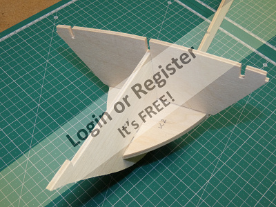
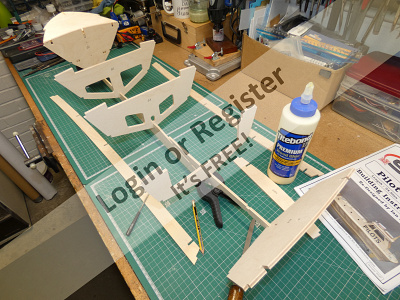
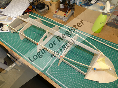
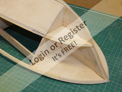
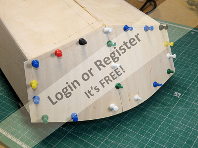
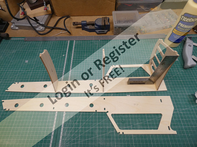
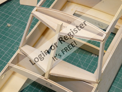
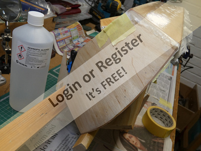
Construction starts with the assembly of the main keel, first bulkhead and the two small parts K2 that lock it together. At this point I’m dry-fitting the parts to ensure that it all slots together correctly. It’s here that a small improvement could be made by re-designing the two smaller parts so that the tabs that slot into the main keel K1 are staggered rather than meet at the same point as the existing slot is long enough. Easily fixed by amending the CNC files but for now it can be fixed by filing each tab to half its length, but I’ll pass on the suggestion to SLEC.
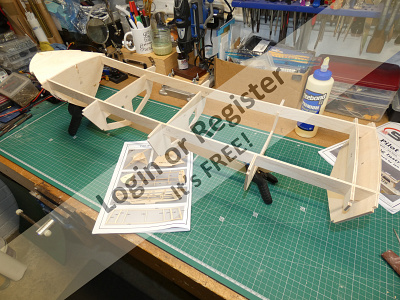
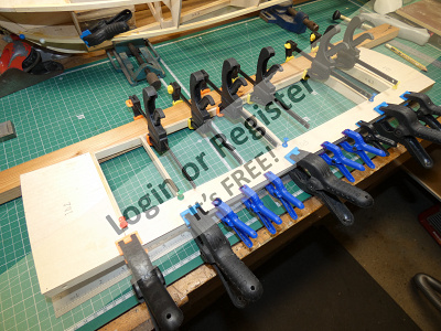
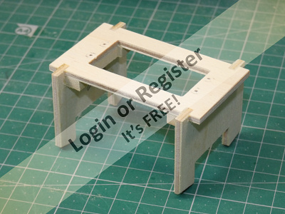
The remaining bulkheads are slotted onto the keel and the two long beams are slotted in at deck level to lock it all together.
When I was happy that all was well I took it apart and re-assembled it all using a waterproof aliphatic PVA glue and a few clamps to hold it all together while the glue sets. A try square was used to check the assembly for square.
In the next part I’ll be fitting the strakes and additional keel parts and constructing the base of the superstructure.

While I was visiting the Warwick International Model Boat Show in November last year I spotted a new model by SLEC of a Harbour Pilots Boat, due for release in Spring 2020.
A quick ‘phone call to them confirmed that it was now available and so I decided to buy the kit and start building it to keep me occupied during the enforced isolation we all find ourselves in at the present.
The kit arrived the following day, very safely packaged in a strong carton, and after opening the box and quickly checking the contents I took out the supplied Building Instruction and Picture Instruction manuals and studied them both at length to familiarise myself with the construction sequence.
Anyone that is familiar with the old Aerokits/Keil Kraft model boats will recognise their characteristic ‘egg crate’ method of construction and this model is a re-working of one such design by Ian Hull for SLEC.
Fortunately I have all the required tools, adhesives and other materials in the workshop including a 10” propshaft and 40mm 2 blade prop that I bought in error for a previous model and so I can make an immediate start. I’ll still need to buy in a receiver, servo, rudder, brushless motor and speed controller and a couple of LiPo batteries at some point but I certainly have all I need to make a start on the build.
All of the plywood parts are CNC router or laser cut and many of the parts lock firmly together with tabs and slots that are already quite a good fit, but however fine the router bit is it can’t produce a sharp 90 degree cut so the first thing the instructions tell you is that you should use a small square file or a sharp knife to square all the internal corner cuts to ensure a proper snug fit.
Construction starts with the assembly of the main keel, first bulkhead and the two small parts K2 that lock it together. At this point I’m dry-fitting the parts to ensure that it all slots together correctly. It’s here that a small improvement could be made by re-designing the two smaller parts so that the tabs that slot into the main keel K1 are staggered rather than meet at the same point as the existing slot is long enough. Easily fixed by amending the CNC files but for now it can be fixed by filing each tab to half its length, but I’ll pass on the suggestion to SLEC.
The remaining bulkheads are slotted onto the keel and the two long beams are slotted in at deck level to lock it all together.
When I was happy that all was well I took it apart and re-assembled it all using a waterproof aliphatic PVA glue and a few clamps to hold it all together while the glue sets. A try square was used to check the assembly for square.
In the next part I’ll be fitting the strakes and additional keel parts and constructing the base of the superstructure.
▲
⟩⟩
hmsnostalgia
Colin H
Missouri
mturpin013
Skydive130
Dibdawg
Rookysailor
RonH
ianed57
swanee
RNinMunich
Martin555
|
💬 Re: SLEC Harbour Pilots Boat by Robbob
4 years ago by 🇬🇧 robbob (
Admiral)✧ 90 Views · 3 Likes
Flag
Hi Mike.
Yes I'm glad to be back in the workshop with a new project to work on 😀 Rob. ▲
⟩⟩
hmsnostalgia
Missouri
Martin555
|
|
Login To
Remove Ads 💬 Re: SLEC Harbour Pilots Boat by Robbob
4 years ago by 🇬🇧 mturpin013 (
Admiral)✧ 90 Views · 2 Likes
Flag
Hi Rob, nice to see you building again
▲
⟩⟩
Missouri
Martin555
|
|
💬 Re: SLEC Harbour Pilots Boat by Robbob
4 years ago by 🇬🇧 Martin555 (
 Fleet Admiral) Fleet Admiral)✧ 91 Views · 2 Likes
Flag
"It will be good to run our builds along side each other and we can certainly bounce of each other with hints and tips ect."
Altho you are both building the same boat It will be interesting as everyone dose things differently. Martin555. ▲
⟩⟩
Missouri
RonH
|
|
💬 Re: SLEC Harbour Pilots Boat by Robbob
4 years ago by 🇬🇧 Skydive130 (
 Rear Admiral) Rear Admiral)✧ 91 Views · 4 Likes
Flag
Hi Rob, I really enjoy your builds especially the descriptions, you should write for that magazine we buy! It was your police launch build that had me buy the that kit, that was a joy to build too.
It will be good to run our builds along side each other and we can certainly bounce of each other with hints and tips ect. 👍 ▲
⟩⟩
hmsnostalgia
Missouri
RonH
Martin555
|
|
💬 Re: SLEC Harbour Pilots Boat by Robbob
4 years ago by 🇺🇸 RonH (
 Chief Petty Officer 1st Class) Chief Petty Officer 1st Class)✧ 96 Views · 3 Likes
Flag
Great looking kit.
▲
⟩⟩
Missouri
Skydive130
Martin555
|
|
💬 Re: SLEC Harbour Pilots Boat by Robbob
4 years ago by 🇩🇪 RNinMunich (
Fleet Admiral)✧ 92 Views · 5 Likes
Flag
Off to another good start Rob👍
And pics in the right order! 😊 Last pic modelled on a medieval torture rack?😮 😁😎 ▲
⟩⟩
grampian31
Missouri
Skydive130
RonH
Martin555
|
Login To
Remove Ads
Remove Ads
📝 Fitting the Chines & Rubbing Strakes
4 years ago by 🇬🇧 robbob ( Admiral)
Admiral)✧ 93 Views · 9 Likes · 7 Comments
Flag
💬 Add Comment
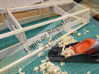
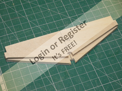
With the main framework of the keel and bulkheads assembled the next stage was to fit the stringers that run the length of the framework on each side.
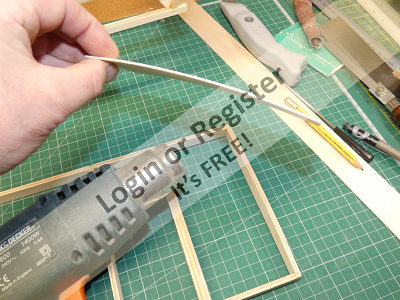
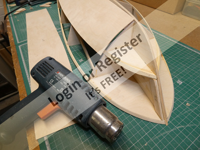
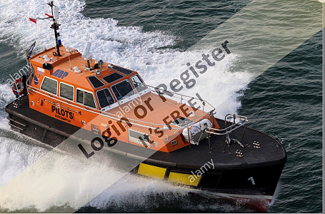
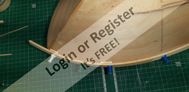
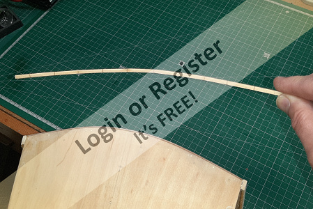
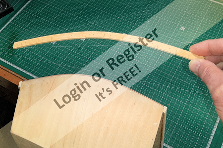
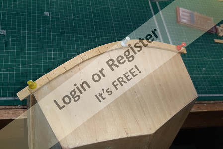
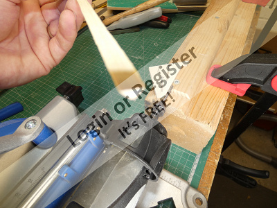
The hull design is a ‘Hard Chine Deep V’ type that gives the real boat its speed and stability characteristics. The lower one is the Hard Chine and the upper one is the Rubbing Strake and these are formed by laminated strips of Obeche hardwood which are shaped to the contours of the hull by planning and sanding at a later stage.
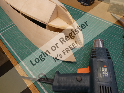
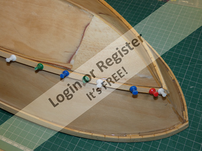
Starting with the lower stringers that form the Hard Chine the notches in all of the bulkheads were filed to the correct angle to ensure that the strips fit properly and the first strip was glued in place and secured with modelling pins. Fortunately the Obeche strip is pliable enough to accommodate the bend at the bow after a little wetting and heating with a heat gun (electric paint stripper). This was repeated for the lower chine on the other side, all the while still checking that the framework was still square.
Fitting the upper Rubbing Strake is a similar operation with the bow ends requiring a bit more bending, but assisted by some cuts made with a razor saw, all the while checking the assembly for true and square.
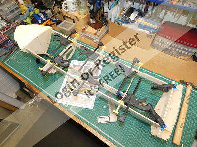
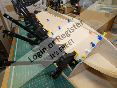
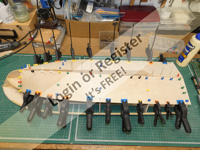
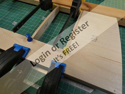
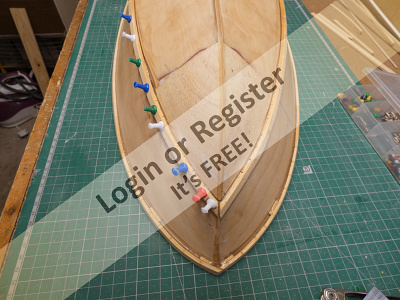
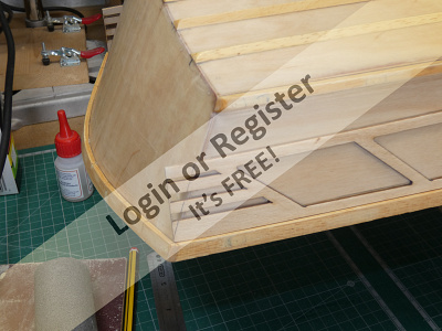
The second laminations were then added to both chines on each side, pinned and clamped all along their lengths and while they were setting the two small keel parts K4 were roughly chamfered to an angle and fitted about 3mm back from the main keel at the bow.
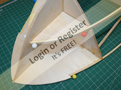
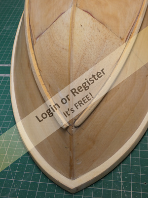
At this point it became evident that there’s another small design error, in that the keel parts K2 need to be re-designed to extend further out to the bow so that the hull skins fit properly where they meet the main keel K1 and the two K4 parts. We saw previously that this part was already in need of modification in the first part of this build blog. So that’s another thing to let SLEC know about but again easily rectified by adding a short third lamination over the Hard Chine back as far as bulkhead B1 that can be sanded back to the correct size and shape.
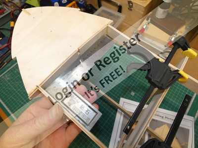
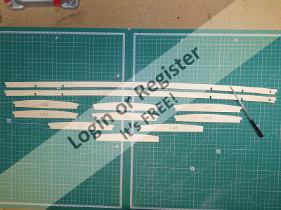
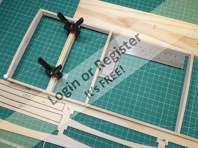
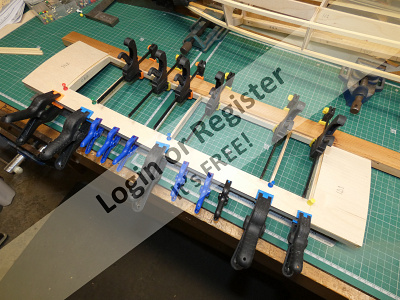
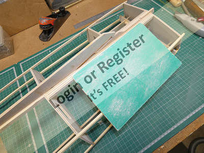
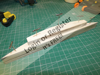
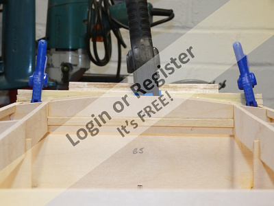
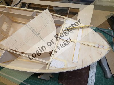
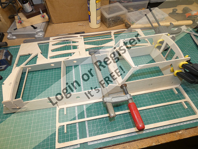
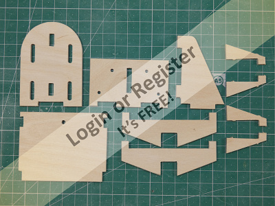
This assembly was then set aside and work was started on the Superstructure Base which has an upward curve along its length that follows the contour of the deck. All the parts for this are laid out in. This ladder type framework needs to be assembled absolutely square and to assist this I fixed down some battens and ply off-cuts and the bench to form a jig to hold all the parts in place during assembly. The upward curve of the Superstructure Base makes this a bit tricky but with all the parts glued, pinned and clamped the piece was carefully checked for true and square and left to set.
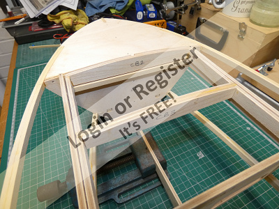
When dry the piece was removed from the jig and, as per instructions, placed in the main hull assembly so that the ends were flush with the bulkheads B1 and B5A so that two strips of Obeche can be added, these locate and support the Superstructure Base at the front and back.
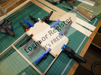
Some 1.5mm ply parts form the inner decking of the Superstructure Base and these are glued, pinned and clamped in place on the framework. At this point it’s vital to check that the assembly is still absolutely square or the base will not fit properly into the main structure.
I used my heat gun to set a slight curvature in the ply panels so that they sit on the frame correctly. The application of heat on the thin 1.5mm ply has the effect of temporarily softening the glue between the plies and relaxing the bond, and allowing the panel to cool while bent will set the bend into the ply. I’ve used this technique to shape the plywood skins on all of my model boats and it’s a much quicker and cleaner method than using steam.
The next part will cover the fitting of some additional keel parts, drilling the keel to take the propshaft and trimming the chines and strakes in preparation for fitting the hull skins.


The hull design is a ‘Hard Chine Deep V’ type that gives the real boat its speed and stability characteristics. The lower one is the Hard Chine and the upper one is the Rubbing Strake and these are formed by laminated strips of Obeche hardwood which are shaped to the contours of the hull by planning and sanding at a later stage.
Starting with the lower stringers that form the Hard Chine the notches in all of the bulkheads were filed to the correct angle to ensure that the strips fit properly and the first strip was glued in place and secured with modelling pins. Fortunately the Obeche strip is pliable enough to accommodate the bend at the bow after a little wetting and heating with a heat gun (electric paint stripper). This was repeated for the lower chine on the other side, all the while still checking that the framework was still square.
Fitting the upper Rubbing Strake is a similar operation with the bow ends requiring a bit more bending, but assisted by some cuts made with a razor saw, all the while checking the assembly for true and square.
The second laminations were then added to both chines on each side, pinned and clamped all along their lengths and while they were setting the two small keel parts K4 were roughly chamfered to an angle and fitted about 3mm back from the main keel at the bow.
At this point it became evident that there’s another small design error, in that the keel parts K2 need to be re-designed to extend further out to the bow so that the hull skins fit properly where they meet the main keel K1 and the two K4 parts. We saw previously that this part was already in need of modification in the first part of this build blog. So that’s another thing to let SLEC know about but again easily rectified by adding a short third lamination over the Hard Chine back as far as bulkhead B1 that can be sanded back to the correct size and shape.
This assembly was then set aside and work was started on the Superstructure Base which has an upward curve along its length that follows the contour of the deck. All the parts for this are laid out in. This ladder type framework needs to be assembled absolutely square and to assist this I fixed down some battens and ply off-cuts and the bench to form a jig to hold all the parts in place during assembly. The upward curve of the Superstructure Base makes this a bit tricky but with all the parts glued, pinned and clamped the piece was carefully checked for true and square and left to set.
When dry the piece was removed from the jig and, as per instructions, placed in the main hull assembly so that the ends were flush with the bulkheads B1 and B5A so that two strips of Obeche can be added, these locate and support the Superstructure Base at the front and back.
Some 1.5mm ply parts form the inner decking of the Superstructure Base and these are glued, pinned and clamped in place on the framework. At this point it’s vital to check that the assembly is still absolutely square or the base will not fit properly into the main structure.
I used my heat gun to set a slight curvature in the ply panels so that they sit on the frame correctly. The application of heat on the thin 1.5mm ply has the effect of temporarily softening the glue between the plies and relaxing the bond, and allowing the panel to cool while bent will set the bend into the ply. I’ve used this technique to shape the plywood skins on all of my model boats and it’s a much quicker and cleaner method than using steam.
The next part will cover the fitting of some additional keel parts, drilling the keel to take the propshaft and trimming the chines and strakes in preparation for fitting the hull skins.
▲
⟩⟩
hmsnostalgia
Colin H
ianed57
Joe727
Missouri
mturpin013
Skydive130
RNinMunich
Martin555
|
💬 Re: Fitting the Chines & Rubbing Strakes
4 years ago by 🇬🇧 robbob (
Admiral)✧ 91 Views · 4 Likes
Flag
Hi Mike.
You're quite right about attention to detail. I seldom,if ever, 'bodge' something to cover up an error of mine as it means I haven't given sufficient forethought to the process, and knowing where the 'bodies are buried' would haunt me (for a while) 🙄. The satisfaction that I know I've done the best that I can is worth the forward planning involved 😇. That's probably why I'm such a relatively slow builder, that's not to say that the fast builders don't do the same planning, it's all a matter of confidence in what you do that enables you to work faster. Self psychoanalysis over.....😉 Rob. ▲
⟩⟩
hmsnostalgia
Martin555
Missouri
Colin H
|
|
Login To
Remove Ads 💬 Re: Fitting the Chines & Rubbing Strakes
4 years ago by 🇬🇧 mturpin013 (
Admiral)✧ 91 Views · 3 Likes
Flag
Without question, attention to detail, not only the parts that show but also the parts that will never be seen, but will have no doubt given you immense satisfaction to know it was done correctly.
▲
⟩⟩
hmsnostalgia
Missouri
Martin555
|
|
💬 Re: Fitting the Chines & Rubbing Strakes
4 years ago by 🇬🇧 Skydive130 (
Rear Admiral)✧ 91 Views · 2 Likes
Flag
Cheers Rob and understood! 👍
▲
⟩⟩
Missouri
Martin555
|
|
💬 Re: Fitting the Chines & Rubbing Strakes
4 years ago by 🇬🇧 robbob (
Admiral)✧ 91 Views · 5 Likes
Flag
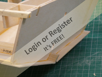
Hi Sy.
Here's a view of the modified stern arrangement of the bottom skins, I don't know why SLEC didn't do it this way 🤔. Rob. 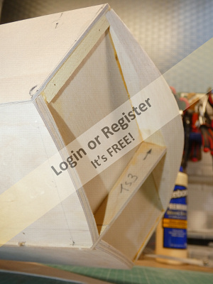
▲
⟩⟩
hmsnostalgia
Colin H
mturpin013
Missouri
Martin555
|
|
💬 Re: Fitting the Chines & Rubbing Strakes
4 years ago by 🇬🇧 robbob (
Admiral)✧ 91 Views · 5 Likes
Flag
Hi Martin.
I'm using Titebond 2 which is an Aliphatic glue for all wood to wood bonding, it dries to a good bond within a hour or so and cures to a very strong bond after that. All other bonding is with Z-Poxy 30 minute epoxy resin. Robbob. 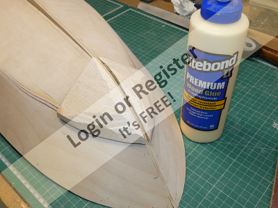
▲
⟩⟩
hmsnostalgia
Colin H
mturpin013
Missouri
Martin555
|
|
💬 Re: Fitting the Chines & Rubbing Strakes
4 years ago by 🇬🇧 Skydive130 (
Rear Admiral)✧ 91 Views · 2 Likes
Flag
I shall watch your transom build with interest Rob, but so far I’ve incorporated your recommendations on stringer extension and will do the same with the sheeting 👍
▲
⟩⟩
Missouri
Martin555
|
|
💬 Re: Fitting the Chines & Rubbing Strakes
4 years ago by 🇬🇧 Martin555 (
Fleet Admiral)✧ 91 Views · 1 Like
Flag
Nice work Robbob.
What glue are you using ? Martin555. ▲
⟩⟩
Missouri
|
📝 Keel Doublers & Bottom Skins
4 years ago by 🇬🇧 robbob ( Admiral)
Admiral)✧ 98 Views · 12 Likes · 5 Comments
Flag
💬 Add Comment
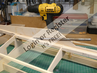
Now that the chine and rubbing strakes are fitted to the bow and bulkheads I have a fairly rigid skeleton on which the skins will be supported. However before the skins go on there are some extra keel parts to fit and these are in the form of laminations that are fitted on either side of the keel. In two places there are two laminations on either side of the main keel piece that thicken and strengthen it to take the propshaft and rudder tubes, and these parts were laminated on the bench and given a slight chamfer with a plane so that the bottom skins fit flush and this is much easier to do before fitting.
There are three spacing tabs in the main keel where the propshaft tube goes, one of which needs to be cut out before the keel laminations are applied and the remaining two are cut away after the doubled-up keel parts are fitted. The rest of the keel laminations are single pieces per side and were also chamfered before fitting.
The strakes and bulkheads now need to be shaped to be as flat as possible and this is easily achieved with my trusty block plane on the stringers and then a final finishing with a ‘sanding plate’ over the stringers and bulkheads. The sanding plate is no more than a piece of MDF about 9” x 6” with an 80 grit abrasive glued on one side and 60 grit on the other and because it is large enough to bridge at least two points on the framework will always remove wood while maintaining a flat ‘plane’ which is essential for the skins to fit properly. At the bow the use of the sanding plate quickly blends the deck part K3 and the chine stringers, including the extra lamination that was fitted to correct a design error. Throughout the planing and sanding process the entire framework was checked flatness using a straight edge to check for any high spots, and because of the use of the sanding plate it’s difficult to introduce any low spots with the plate supported over two or three places.
The keel was then drilled to take the 8mm propshaft tube, fortunately I have a suitably long 8mm bit for this. A final finishing with a long round file was needed to neaten it up and provide a loose friction fit for the tube. I won’t epoxy the tube in place until I have all the parts of the drive train to hand to ensure that the alignment is as accurate as possible. The rudder position is pre-marked on the keel by a notch in the main keel but I’ll be leaving the drilling of the rudder fixing hole until the all the skins are fitted.
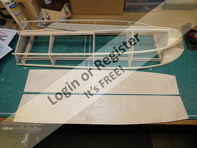
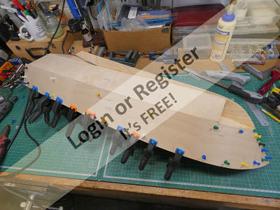
The bottom skins are fitted first and are quite accurately CNC cut and only require minimal trimming and chamfering where the skin meets the keel. I used my ‘heat Gun’ technique to put a permanent bend in the 1.5mm skins so that they conform quite closely to the curvatures at the bow and but some modelling pins and a few clamps are still needed to hold them in place when glued. The skins are fitted from bulkhead B1 to the stern with the bow section being formed from carved balsa blocks. When fitted correctly the bottom skins extend beyond the stern bulkhead B5 by a couple of centimetres and the instructions tell you to trim them back to B5 and then fit some extra parts to form the curved transom but I’m going to re-work this by taking advantage of the surplus bottom skin overlaps which I think is a much better solution.
It the time of writing (mid April) I’m still waiting for the rudder and motor coupling I have ordered from the UK supplier, and most frustratingly the motor, speed controller, battery and RC receiver are all out of stock with my usual supplier for these bits (HobbyKing’s UK warehouse is temporarily closed under the Covid-19 restrictions) with the hold-up most likely as a result of the shutdown of the Chinese factories that produce the majority of these items these days.
In the next part I’ll be fitting the side skins, shaping and fixing the balsa bow blocks and building the curved transom.
There are three spacing tabs in the main keel where the propshaft tube goes, one of which needs to be cut out before the keel laminations are applied and the remaining two are cut away after the doubled-up keel parts are fitted. The rest of the keel laminations are single pieces per side and were also chamfered before fitting.
The strakes and bulkheads now need to be shaped to be as flat as possible and this is easily achieved with my trusty block plane on the stringers and then a final finishing with a ‘sanding plate’ over the stringers and bulkheads. The sanding plate is no more than a piece of MDF about 9” x 6” with an 80 grit abrasive glued on one side and 60 grit on the other and because it is large enough to bridge at least two points on the framework will always remove wood while maintaining a flat ‘plane’ which is essential for the skins to fit properly. At the bow the use of the sanding plate quickly blends the deck part K3 and the chine stringers, including the extra lamination that was fitted to correct a design error. Throughout the planing and sanding process the entire framework was checked flatness using a straight edge to check for any high spots, and because of the use of the sanding plate it’s difficult to introduce any low spots with the plate supported over two or three places.
The keel was then drilled to take the 8mm propshaft tube, fortunately I have a suitably long 8mm bit for this. A final finishing with a long round file was needed to neaten it up and provide a loose friction fit for the tube. I won’t epoxy the tube in place until I have all the parts of the drive train to hand to ensure that the alignment is as accurate as possible. The rudder position is pre-marked on the keel by a notch in the main keel but I’ll be leaving the drilling of the rudder fixing hole until the all the skins are fitted.
The bottom skins are fitted first and are quite accurately CNC cut and only require minimal trimming and chamfering where the skin meets the keel. I used my ‘heat Gun’ technique to put a permanent bend in the 1.5mm skins so that they conform quite closely to the curvatures at the bow and but some modelling pins and a few clamps are still needed to hold them in place when glued. The skins are fitted from bulkhead B1 to the stern with the bow section being formed from carved balsa blocks. When fitted correctly the bottom skins extend beyond the stern bulkhead B5 by a couple of centimetres and the instructions tell you to trim them back to B5 and then fit some extra parts to form the curved transom but I’m going to re-work this by taking advantage of the surplus bottom skin overlaps which I think is a much better solution.
It the time of writing (mid April) I’m still waiting for the rudder and motor coupling I have ordered from the UK supplier, and most frustratingly the motor, speed controller, battery and RC receiver are all out of stock with my usual supplier for these bits (HobbyKing’s UK warehouse is temporarily closed under the Covid-19 restrictions) with the hold-up most likely as a result of the shutdown of the Chinese factories that produce the majority of these items these days.
In the next part I’ll be fitting the side skins, shaping and fixing the balsa bow blocks and building the curved transom.
▲
⟩⟩
hmsnostalgia
MouldBuilder
RNinMunich
Rookysailor
mturpin013
Missouri
Colin H
RonH
Martin555
Joe727
Skydive130
ianed57
|
💬 Re: Keel Doublers & Bottom Skins
4 years ago by 🇬🇧 mturpin013 (
Admiral)✧ 95 Views · 4 Likes
Flag
Nice work as usual, I like the use of the flat board with grades of abrasive on each side I have used this method for all sorts of woodwork projects not just models, Its value is immeasurable for creating that flat surface.
▲
⟩⟩
Missouri
RNinMunich
Joe727
Martin555
|
|
Login To
Remove Ads 💬 Re: Keel Doublers & Bottom Skins
4 years ago by 🇬🇧 robbob (
Admiral)✧ 94 Views · 2 Likes
Flag
Martin.
Not much chance of me writing anything for Model Boats Magazine from what I understand from their dormant state at the moment☹️. I really do hope they pull through 🤞 Interestingly they had a 'Fire Sale' on back issues a few days ago at 99p each so I picked up a few that had content that took my interest including a November 2012 edition with an article on a Harbour Pilots Boat kit review. Robbob. 
▲
⟩⟩
Missouri
Martin555
|
|
💬 Re: Keel Doublers & Bottom Skins
4 years ago by 🇺🇸 RonH (
Chief Petty Officer 1st Class)✧ 108 Views · 2 Likes
Flag
Great picture on your build. Looking great, cannot wait to see more.
▲
⟩⟩
Martin555
Missouri
|
|
💬 Re: Keel Doublers & Bottom Skins
4 years ago by 🇬🇧 Martin555 (
Fleet Admiral)✧ 94 Views · 2 Likes
Flag
Looking good Robbob.
You should definitely do articles for model boat magazines. Martin555. ▲
⟩⟩
hmsnostalgia
Missouri
|
|
💬 Re: Keel Doublers & Bottom Skins
4 years ago by 🇺🇸 Joe727 (
 Commander) Commander)✧ 94 Views · 1 Like
Flag
Great write up and photos, thsnks!
Joe👍 ▲
⟩⟩
Missouri
|
📝 Side Skins, Bow Blocks & Transom
4 years ago by 🇬🇧 robbob ( Admiral)
Admiral)✧ 104 Views · 13 Likes · 7 Comments
Flag
💬 Add Comment
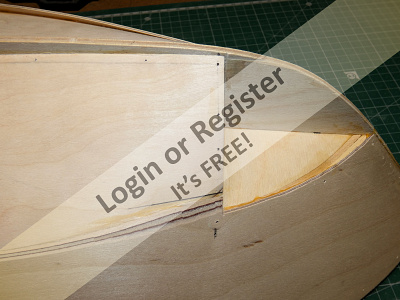
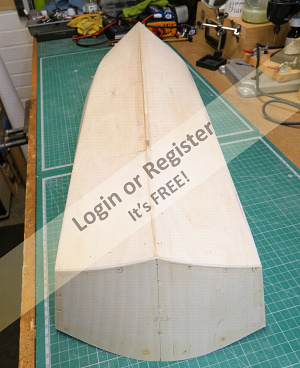
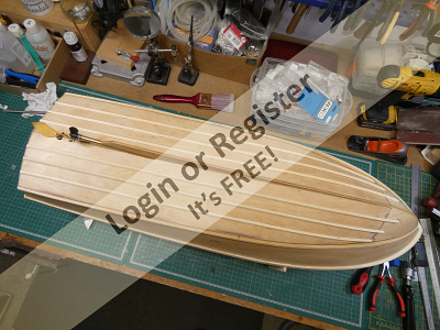
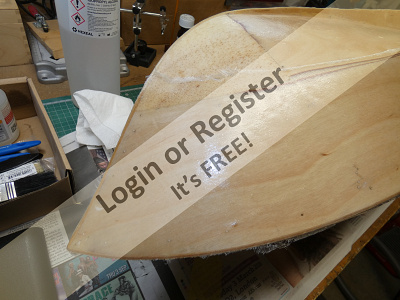
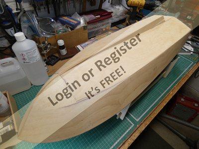
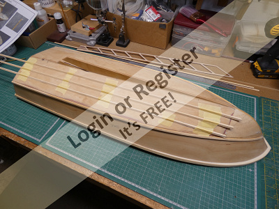
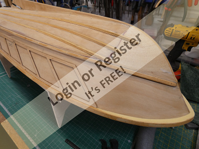
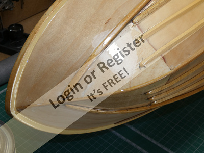
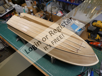
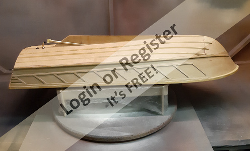
With the bottom skins firmly fixed in place and the glue set, all of the clamps and pins were removed and I was then able to trim them back to the lower chine using my small block plane and sanding plate paying particular attention to the area where the side skins overlap the bottom skins at bulkhead B1.
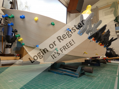
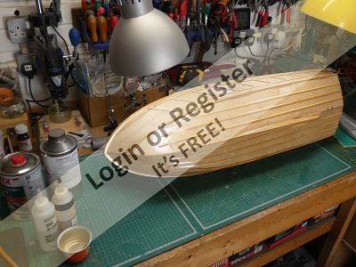
The application of the side skins is also quite straightforward and again I used my heat gun to pre-form the skins to the shape of the hull at the bow. It’s quite remarkable how well the heating a bending of the skins works and the process only takes a few minutes to achieve the correct curvatures. All of this means that the skins sit almost perfectly on the hull framework first time and really don’t need to be forced in place. Despite this advantage I still prefer to fix the skins down with pins and clamps as the aliphatic glue sets.
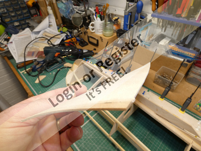
The side skins need to be trimmed back at the deck level and the chine and it’s very satisfying to see the hull taking shape. The side skins were blended into the bottom skins at bulkhead B1 and the excess overlaps of all skins carefully removed at B1 and K3 to allow for the fitting of the balsa blocks that form the lower part of the bow.
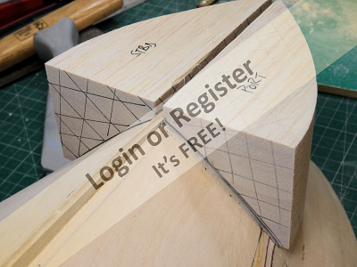
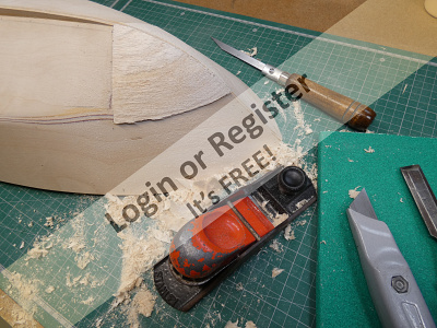
The supplied balsa blocks needed to be sanded back slightly on one face to fit properly into the recess formed by the main keel K1, bulkhead B1 and the formers K3 because those parts don’t form a true internal square but it’s easy to sand back one face of the blocks on my rotary sander. Before glueing in place the waste areas of the blocks were marked and removed with a razor saw. When set the medium hardness balsa blocks are very quickly and easily shaped with a block plane and sanding plate, and the whole of the bow area was then blended together into the bottom and side skins and the keel.
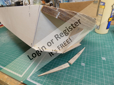
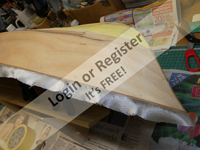
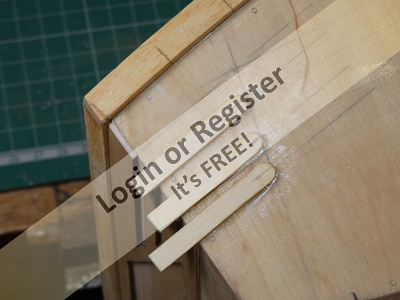
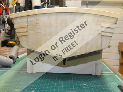
Moving to the other end of the hull, constructing the stern is the next stage described in the supplied instructions. This starts with the lamination of three balsa parts that form the upper part of the stern which are glued in place and then sanded back to the curvature of the rear deck. The transom former TS3 was then fitted between the keel and the balsa lamination.
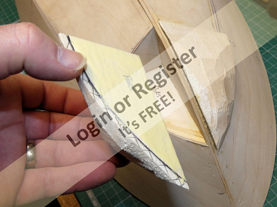
Because I have sufficient overlap of the bottom skins I decided to fit the lower transom formers TS4 inside the skins, this involved just re-shaping them slightly to fit against the bottom skins and the bulkhead part B5. After the addition of two outer strips of obeche the whole area was then sanded back to the correct curved profile of the stern. This deviation from the supplied instructions means that the bottom skins are continuous to the stern and I think make for a stronger and neater finish. This is another thing that I may suggest to SLEC as a possible modification.
The inside faces of the stern cavity and the internal exposed areas of the stern skin were given a couple of coats of sanding sealer (but not over the glueing areas) as a precaution against any ingress of water affecting the wood as later on I will be piercing the stern to fit the ESC water cooling outlet tube.
Finally the stern skin ST5 was glued and pinned in place, as before this skin was heated and pre-formed with a heat gun and when the glues had set the skin was trimmed and sanded back flush to the side and bottom skins.
As with my other models I will be using glassfibre cloth and epoxy resin over the whole hull to add strength and to provide a good surface for the paint finishes. The hull still needs the addition of some bottom and side rubbing strakes once the fibre and epoxy stage is done.
The application of the side skins is also quite straightforward and again I used my heat gun to pre-form the skins to the shape of the hull at the bow. It’s quite remarkable how well the heating a bending of the skins works and the process only takes a few minutes to achieve the correct curvatures. All of this means that the skins sit almost perfectly on the hull framework first time and really don’t need to be forced in place. Despite this advantage I still prefer to fix the skins down with pins and clamps as the aliphatic glue sets.
The side skins need to be trimmed back at the deck level and the chine and it’s very satisfying to see the hull taking shape. The side skins were blended into the bottom skins at bulkhead B1 and the excess overlaps of all skins carefully removed at B1 and K3 to allow for the fitting of the balsa blocks that form the lower part of the bow.
The supplied balsa blocks needed to be sanded back slightly on one face to fit properly into the recess formed by the main keel K1, bulkhead B1 and the formers K3 because those parts don’t form a true internal square but it’s easy to sand back one face of the blocks on my rotary sander. Before glueing in place the waste areas of the blocks were marked and removed with a razor saw. When set the medium hardness balsa blocks are very quickly and easily shaped with a block plane and sanding plate, and the whole of the bow area was then blended together into the bottom and side skins and the keel.
Moving to the other end of the hull, constructing the stern is the next stage described in the supplied instructions. This starts with the lamination of three balsa parts that form the upper part of the stern which are glued in place and then sanded back to the curvature of the rear deck. The transom former TS3 was then fitted between the keel and the balsa lamination.
Because I have sufficient overlap of the bottom skins I decided to fit the lower transom formers TS4 inside the skins, this involved just re-shaping them slightly to fit against the bottom skins and the bulkhead part B5. After the addition of two outer strips of obeche the whole area was then sanded back to the correct curved profile of the stern. This deviation from the supplied instructions means that the bottom skins are continuous to the stern and I think make for a stronger and neater finish. This is another thing that I may suggest to SLEC as a possible modification.
The inside faces of the stern cavity and the internal exposed areas of the stern skin were given a couple of coats of sanding sealer (but not over the glueing areas) as a precaution against any ingress of water affecting the wood as later on I will be piercing the stern to fit the ESC water cooling outlet tube.
Finally the stern skin ST5 was glued and pinned in place, as before this skin was heated and pre-formed with a heat gun and when the glues had set the skin was trimmed and sanded back flush to the side and bottom skins.
As with my other models I will be using glassfibre cloth and epoxy resin over the whole hull to add strength and to provide a good surface for the paint finishes. The hull still needs the addition of some bottom and side rubbing strakes once the fibre and epoxy stage is done.
▲
⟩⟩
Colin H
hmsnostalgia
nasraf
marky
Missouri
ianed57
RNinMunich
mturpin013
MouldBuilder
Graham93
Skydive130
RonH
Martin555
|
💬 Re: Side Skins, Bow Blocks & Transom
4 years ago by 🇬🇧 marky (
 Commodore) Commodore)✧ 97 Views · 2 Likes
Flag
Nice one Robb.
Cheers Marky👍 ▲
⟩⟩
Martin555
robbob
|
|
Login To
Remove Ads 💬 Re: Side Skins, Bow Blocks & Transom
4 years ago by 🇩🇪 RNinMunich (
Fleet Admiral)✧ 98 Views · 3 Likes
Flag
I can never resist a good 'feeder line' Rob.
Good work. Keep it up👍😉 Doug 😎 ▲
⟩⟩
Missouri
Martin555
robbob
|
|
💬 Re: Side Skins, Bow Blocks & Transom
4 years ago by 🇬🇧 robbob (
Admiral)✧ 98 Views · 3 Likes
Flag
Doug, you're a master of the 'double entendre'.
Thanks for your praise, I'll try to keep my end up 😆 Rob. ▲
⟩⟩
Missouri
Martin555
RNinMunich
|
|
💬 Re: Side Skins, Bow Blocks & Transom
4 years ago by 🇩🇪 RNinMunich (
Fleet Admiral)✧ 98 Views · 3 Likes
Flag
Always good to have your bottom skins firmly in place Rob😁😂🤣
Never mind the 'bottom rubbing' strakes 😮 Another Master Class in hull building 👍👍 Cheers, Doug 😎 ▲
⟩⟩
hmsnostalgia
Missouri
Martin555
|
|
💬 Re: Side Skins, Bow Blocks & Transom
4 years ago by 🇬🇧 robbob (
Admiral)✧ 98 Views · 2 Likes
Flag
Must seem like Déjà vu seeing my blog updates appearing Sy. 😉
The thing is I actually wrote them all while ago but I need to keep posting them and at your rate of productivity you'll still finish way before I do 😁 Rob. ▲
⟩⟩
Missouri
Martin555
|
|
💬 Re: Side Skins, Bow Blocks & Transom
4 years ago by 🇬🇧 Skydive130 (
Rear Admiral)✧ 99 Views · 4 Likes
Flag
It’s like watching my own build Rob ha ha!
▲
⟩⟩
marky
Missouri
RNinMunich
Martin555
|
|
💬 Re: Side Skins, Bow Blocks & Transom
4 years ago by 🇬🇧 Martin555 (
Fleet Admiral)✧ 100 Views · 4 Likes
Flag
Nice work Robbob,
Keep up the good work. Martin555. ▲
⟩⟩
hmsnostalgia
marky
Missouri
RonH
|
📝 Fitting the deck skins and building the superstructure.
4 years ago by 🇬🇧 robbob ( Admiral)
Admiral)✧ 105 Views · 14 Likes · 9 Comments
Flag
💬 Add Comment
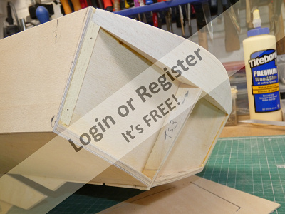
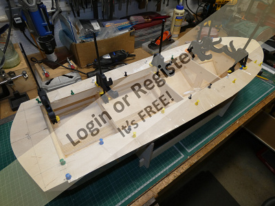
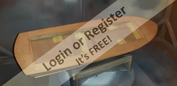
At this stage I can set the hull aside and continue work on the superstructure base which fits inside the deck aperture. If the base has been constructed properly it should fit inside the deck with a couple of millimetres clearance all round and be should be flush with the deck framework all around.
Two pieces of obeche strip were previously added to the insides of the deck aperture to support the framework at the front and rear making sure that the framework is still flush all round, if it’s not there might be a twist that needs to be corrected.
Fortunately my base was OK and so I just used my sanding plate on the base of the frame to take off any high spots.
The whole deck area was also sanded to remove any high spots too. Knowing that all was as it should be I glued and pinned the obeche strips in place. The 1.5mm ply inner deck skins were then glued and pinned to the framework all the while checking that the frame was still square. When the glue had set I trimmed the skins back to the frame leaving a very small overlap to allow for finer adjustment later after the deck skins have been added.
The deck skins were added next starting with the piece that covers the bow, but before fitting it I added some additional strips of obeche and balsa to add extra support to the bow skin, this is so that when I add deck fitting at a later stage they will be supported properly. Those extra bits were sanded to the correct curved profile of the deck using the sanding plate and the upper part of bulkhead B1 as a guide.
I fitted the skin at the bow first, followed by the rear deck. The deck side skins need some additional support strips of scrap obeche fitted in a couple of places before the skins were glued and pinned in place. After the glue had set I then trimmed all of the deck skins flush with the hull sides all round.
A small amount of trimming of all of the skins was required for the superstructure base to fit into the deck aperture and if all is well the skins should all be reasonably flush.
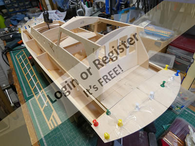
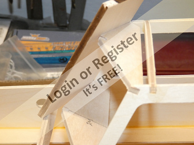
The cabin is assembled as a separate part that is fixed on top of the superstructure base. One of the cabin sides is laid flat and three cabin formers are fixed into it using the tabs and slots in all the parts and then the other side of the cabin former is attached.
This assembly was then glued and clamped together making sure that it was square and without any twist. Various additional formers were then added that form the engine room front face and other parts that form the cabin windscreen and rear door panel.
There appears to be another slight error in one of the windscreen formers that would prevent the windscreen panels sitting properly in the same plane so I re-made this part in new ply to make it to the correct angle, another item to bring SLEC’s attention to.
Two pieces of obeche strip were previously added to the insides of the deck aperture to support the framework at the front and rear making sure that the framework is still flush all round, if it’s not there might be a twist that needs to be corrected.
Fortunately my base was OK and so I just used my sanding plate on the base of the frame to take off any high spots.
The whole deck area was also sanded to remove any high spots too. Knowing that all was as it should be I glued and pinned the obeche strips in place. The 1.5mm ply inner deck skins were then glued and pinned to the framework all the while checking that the frame was still square. When the glue had set I trimmed the skins back to the frame leaving a very small overlap to allow for finer adjustment later after the deck skins have been added.
The deck skins were added next starting with the piece that covers the bow, but before fitting it I added some additional strips of obeche and balsa to add extra support to the bow skin, this is so that when I add deck fitting at a later stage they will be supported properly. Those extra bits were sanded to the correct curved profile of the deck using the sanding plate and the upper part of bulkhead B1 as a guide.
I fitted the skin at the bow first, followed by the rear deck. The deck side skins need some additional support strips of scrap obeche fitted in a couple of places before the skins were glued and pinned in place. After the glue had set I then trimmed all of the deck skins flush with the hull sides all round.
A small amount of trimming of all of the skins was required for the superstructure base to fit into the deck aperture and if all is well the skins should all be reasonably flush.
The cabin is assembled as a separate part that is fixed on top of the superstructure base. One of the cabin sides is laid flat and three cabin formers are fixed into it using the tabs and slots in all the parts and then the other side of the cabin former is attached.
This assembly was then glued and clamped together making sure that it was square and without any twist. Various additional formers were then added that form the engine room front face and other parts that form the cabin windscreen and rear door panel.
There appears to be another slight error in one of the windscreen formers that would prevent the windscreen panels sitting properly in the same plane so I re-made this part in new ply to make it to the correct angle, another item to bring SLEC’s attention to.
▲
⟩⟩
Colin H
hmsnostalgia
ianed57
Missouri
MouldBuilder
Joe727
RNinMunich
mturpin013
Hillro
Rookysailor
Scratchbuilder
RonH
marky
Martin555
|
💬 Re: Fitting the deck skins and building the superstructure.
4 years ago by 🇭🇺 MouldBuilder (
 Vice Admiral) Vice Admiral)✧ 98 Views · 4 Likes
Flag
Very nice work. Some of the blogs on this site are really good reference works for those, like me, who have a lot to learn. Yours are up there with the very best. It is a very useful feature of this site where you can print a full build booklet. Much better than the supplied instructions. Thanks for taking the trouble to do detailed logs and great pictures.👍👍👍
▲
⟩⟩
hmsnostalgia
Missouri
robbob
Martin555
|
|
Login To
Remove Ads 💬 Re: Fitting the deck skins and building the superstructure.
4 years ago by 🇺🇸 Joe727 (
Commander)✧ 98 Views · 3 Likes
Flag
Robbob,
Nice write-up and great photos, thanks for the detail. Joe ▲
⟩⟩
hmsnostalgia
Missouri
Martin555
|
|
💬 Re: Fitting the deck skins and building the superstructure.
4 years ago by 🇬🇧 robbob (
Admiral)✧ 98 Views · 3 Likes
Flag
Hi Mike.
It's one of three errors I found in the kit, perhaps these issues have been fixed in later production runs. I wonder if Skydive130 (Sy) found the same errors in his kit ?..particularly the cabin window frame error. Rob. ▲
⟩⟩
hmsnostalgia
Missouri
Martin555
|
|
💬 Re: Fitting the deck skins and building the superstructure.
4 years ago by 🇬🇧 mturpin013 (
Admiral)✧ 99 Views · 4 Likes
Flag
Coming on nicely Rob, Its a shame that a kit such as this has errors in it, I would have thought these would have been sort long ago. I can imagine many modelers have struggled with glue and pins trying to get the front frame to stay in place😠
▲
⟩⟩
RonH
Missouri
Martin555
robbob
|
|
💬 Re: Fitting the deck skins and building the superstructure.
4 years ago by 🇬🇧 robbob (
Admiral)✧ 100 Views · 8 Likes
Flag
Hi Sy.
It will be interesting to see how you re-model the cabin, I'm beginning to wish I'd thought about something different for the cabin now 🤔. Still, I'm too far down the line to change much now. The bottom strakes worked out well, nicely planed to the triangular section and all in place now. My rubber fenders arrived today..but they sent 13mm instead of 10mm ...Grrrr 😠 but the 6mm is just right for the side fender frames. Rob. 
▲
⟩⟩
Colin H
hmsnostalgia
Missouri
MouldBuilder
Joe727
Rookysailor
mturpin013
Martin555
|
|
💬 Re: Fitting the deck skins and building the superstructure.
4 years ago by 🇬🇧 Skydive130 (
Rear Admiral)✧ 98 Views · 3 Likes
Flag
Hi Rob, lovely well written post as usual. I’m not far from starting my cabin build and that’s were our builds will start to differ as I plan to change the cabin shape. Fist challenge will be to fill in the port holes as my planed version doesn’t have them!
▲
⟩⟩
Missouri
Martin555
robbob
|
|
💬 Re: Fitting the deck skins and building the superstructure.
4 years ago by 🇬🇧 Rookysailor (
Commodore)✧ 98 Views · 3 Likes
Flag
Excellent quality build Rob, I see what you mean about the windscreen former, don't recall having that problem on my lesro build, but I think you are correct to contact SLEC about it.😐
Cheers, Pete ▲
⟩⟩
Missouri
robbob
Martin555
|
|
💬 Re: Fitting the deck skins and building the superstructure.
4 years ago by 🇺🇸 RonH (
Chief Petty Officer 1st Class)✧ 114 Views · 2 Likes
Flag
You really do nice work, looking good.
▲
⟩⟩
Missouri
Martin555
|
|
💬 Re: Fitting the deck skins and building the superstructure.
4 years ago by 🇬🇧 Martin555 (
Fleet Admiral)✧ 98 Views · 1 Like
Flag
Good work robbob.
She is coming together nicely. Martin555. ▲
⟩⟩
Missouri
|
📝 Re-thinking the cabin and fibre-glassing the hull.
4 years ago by 🇬🇧 robbob ( Admiral)
Admiral)✧ 105 Views · 13 Likes · 5 Comments
Flag
💬 Add Comment
I have decided to hold off from completing the superstructure for a while I consider constructing an alternative design of cabin. There is a particularly good example of a more authentic cabin structure on a Harbour Pilots Boat that operates in Southampton Water and Skydive130 is making the same SLEC kit as me and is altering the cabin design on his to mimic the Southampton boat and making a very decent job of it👍, so much so that I think I will be altering mine in the same way. So although my cabin was actually completed weeks ago I'll be scrapping it and starting again.😮
Meanwhile I can continue with my build by applying the glassfibre cloth and epoxy resin to the hull.😁
On all the boats I have built before I have done this to reinforce the hull and to provide a good surface for the paint finishes. The first stage is to give the entire hull a good sanding with a 180 grit paper and then brushing off all the dust followed by a thorough clean with some panel wipe to remove any residue of oil, grease or silicones that would react with the epoxy resin.
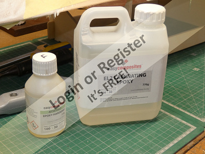
I used a 100gsm (grams per sq metre) woven twill cloth with a fast setting epoxy resin mix that has a 30 minute ‘pot life’ before the resin starts to become unworkable.
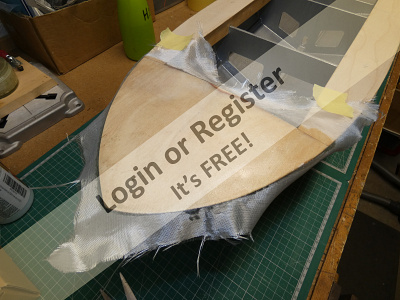
My preferred method is to apply a coat of resin over the hull and then gently lay the cloth into the resin and then lightly brushing from the centre of the cloth outwards without applying any additional resin, this ensures that the cloth settles into the resin and any creases or bumps are easily brushed out.
I applied the glassfibre cloth in five stages starting with one side of the bottom of the hull and when set continuing with the other four faces of the hull the last being the transom. This process usually takes a few days but the resulting cloth and resin surface is free from ripples and bubbles and I can then give the whole hull a light sanding to flatten the surfaces.
Previously I have used additional coats of the EasyComposites resin but on this occasion I used Z-Poxy Finishing Resin because the cure time is about four hours which means that I was able to apply a second coat of resin over the entire hull, again in five stages over the course of a single day. I have found the Z-Poxy finishing resin far less susceptible to producing streaks and ‘fish eye’ blemishes in the surface, but I still clean over the entire area with fast evaporating ‘panel wipe’ to remove any last traces of silicones or oils from my hands and fingers.
After leaving the resin to cure completely overnight I was able to sand the entire hull with a 480 grit ‘wet & dry’ abrasive paper used wet to flatten the epoxy to a fine finish.
The next stage will be to fit all of the rubbing, chine and lift strakes.


Meanwhile I can continue with my build by applying the glassfibre cloth and epoxy resin to the hull.😁
On all the boats I have built before I have done this to reinforce the hull and to provide a good surface for the paint finishes. The first stage is to give the entire hull a good sanding with a 180 grit paper and then brushing off all the dust followed by a thorough clean with some panel wipe to remove any residue of oil, grease or silicones that would react with the epoxy resin.
I used a 100gsm (grams per sq metre) woven twill cloth with a fast setting epoxy resin mix that has a 30 minute ‘pot life’ before the resin starts to become unworkable.
My preferred method is to apply a coat of resin over the hull and then gently lay the cloth into the resin and then lightly brushing from the centre of the cloth outwards without applying any additional resin, this ensures that the cloth settles into the resin and any creases or bumps are easily brushed out.
I applied the glassfibre cloth in five stages starting with one side of the bottom of the hull and when set continuing with the other four faces of the hull the last being the transom. This process usually takes a few days but the resulting cloth and resin surface is free from ripples and bubbles and I can then give the whole hull a light sanding to flatten the surfaces.
Previously I have used additional coats of the EasyComposites resin but on this occasion I used Z-Poxy Finishing Resin because the cure time is about four hours which means that I was able to apply a second coat of resin over the entire hull, again in five stages over the course of a single day. I have found the Z-Poxy finishing resin far less susceptible to producing streaks and ‘fish eye’ blemishes in the surface, but I still clean over the entire area with fast evaporating ‘panel wipe’ to remove any last traces of silicones or oils from my hands and fingers.
After leaving the resin to cure completely overnight I was able to sand the entire hull with a 480 grit ‘wet & dry’ abrasive paper used wet to flatten the epoxy to a fine finish.
The next stage will be to fit all of the rubbing, chine and lift strakes.
▲
⟩⟩
Ronald
Colin H
hmsnostalgia
mturpin013
RonH
Missouri
jbkiwi
Joe727
Rookysailor
MouldBuilder
ianed57
Martin555
Skydive130
|
💬 Re: Re-thinking the cabin and fibre-glassing the hull.
4 years ago by 🇬🇧 hmsnostalgia (
 Petty Officer 1st Class) Petty Officer 1st Class)✧ 99 Views · 1 Like
Flag
Hi Robbob, have you considered repurposing the original superstructure or offering it to other builders ??; good looking job so far, by the way!!. 👍👌
▲
⟩⟩
Martin555
|
|
Login To
Remove Ads 💬 Re: Re-thinking the cabin and fibre-glassing the hull.
4 years ago by 🇺🇸 Joe727 (
Commander)✧ 100 Views · 2 Likes
Flag
Rob,
Nice write-up and photos, good information on your fiberglassing method. Always good to have more information on techniques. Joe ▲
⟩⟩
Missouri
Martin555
|
|
💬 Re: Re-thinking the cabin and fibre-glassing the hull.
4 years ago by 🇬🇧 robbob (
Admiral)✧ 101 Views · 4 Likes
Flag
Hi Peter.I
Thanks for your comments. There will be a final epoxy coat to go on after all the strakes are fitted but at this stage it's a strong and watertight hull, or it would be if the propshaft and rudder were filling the holes 😀!. Rob. ▲
⟩⟩
hmsnostalgia
RonH
Missouri
Martin555
|
|
💬 Re: Re-thinking the cabin and fibre-glassing the hull.
4 years ago by 🇭🇺 MouldBuilder (
Vice Admiral)✧ 100 Views · 3 Likes
Flag
Nice job. The finish on the glass looks really good. I will give this a try when I get around to my 46" Crash Tender.👍
Peter. ▲
⟩⟩
Missouri
Martin555
robbob
|
|
💬 Re: Re-thinking the cabin and fibre-glassing the hull.
4 years ago by 🇬🇧 Skydive130 (
Rear Admiral)✧ 101 Views · 4 Likes
Flag
Hi Rob, many thanks for your compliments on my modified cabin superstructure and very much looking forward to seeing how yours shapes up! I’ll be sending the dimensions via PM shortly.
Kind regards Sy ▲
⟩⟩
RonH
Missouri
Martin555
robbob
|
📝 Fitting the Strakes and Chines.
4 years ago by 🇬🇧 robbob ( Admiral)
Admiral)✧ 107 Views · 14 Likes · 3 Comments
Flag
💬 Add Comment
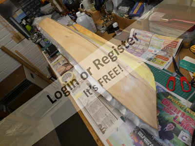
The final bit of the glassfibre and resin stage was to apply some 50 gsm cloth to the deck, again with the Z-Poxy Finishing Resin. The whole deck surface was covered and then rubbed down to receive a second coat of resin. This deck area will later be finished with a textured coating to simulate the anti-slip surface that is usually found on service boats such as this so it’s not essential for me to finish the epoxy to a fine surface.
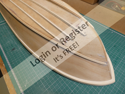
The rubbing strakes around the hull at deck level were tackled next and I chose to fit a 10mm wide strake rather than the one supplied in the kit. This is so that I can later fit a 10mm wide half round neoprene ‘D’ profile ‘bumper’ around the deck. The Obeche hardwood strip I used had to be ‘heat bent’ to roughly the correct curvature of the bow and I also put some relief cuts with a razor saw so that the strake could also be formed in a second plane, a somewhat torturous process for the wood to get it to conform to the bow shape particularly as I wanted the strake to be mostly vertical around the hull so that the ‘D’ profile rubber looked correct.
To achieve this I also had to fit some small spacer pieces at the bow to push the bottom edge of the strake away from the hull. The first strake was glued and pinned in place and when set the other side was fitted with an overlap at the tip of the bow which will be later ‘rounded’ so that the rubber strip goes around it smoothly. All the gaps at the bow were filled with a two part wood filler after the overlap was cut off.
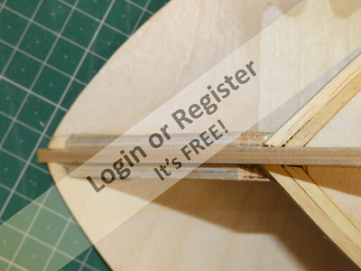
The chine strakes are also Obeche hardwood strips that needed some razor saw cuts at the bow and they were both fixed with epoxy resin glue and holding pins. The instructions are a bit vague on where they should finish on the bow keel so I had to judge this by eye with reference to the ‘photos in the instructions. I didn’t shape these strakes before fitting because it would be easier to put a small chamfer on the upper edge and shape the bow and stern ends after they were fitted.
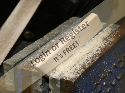
The strakes on the underside of the hull act as lifting strakes to help the hull rise when planning at speed, the instructions say that the supplied 5mm square Obeche strips should be sanded to a half round profile before fitting but I decided to make them to the true shape of a lift strake by machining them to a triangular profile. This proved more difficult to achieve than I thought, my first attempt being to try to mill them using a jig and my Dremel with a milling bit. This was not too successful and I found it far easier to just lay the Obeche strip in the long groove of an off-cut of decking timber and planning it down along its length.
I was clearly over-thinking something that was not really a problem, and the simple solution was the best.🤓
When all the strips were prepared I laid them on the hull bottom at the required spacing and pencil marked the hull with some guide lines. A small amount of bending and some relief cuts were required on each before they were all glued in place with epoxy and when set the ends were trimmed and shaped.
The side rubbing strake 'lattice' pieces will need to be added before the hull gets its final coat(s) of epoxy finishing resin. 😁


The rubbing strakes around the hull at deck level were tackled next and I chose to fit a 10mm wide strake rather than the one supplied in the kit. This is so that I can later fit a 10mm wide half round neoprene ‘D’ profile ‘bumper’ around the deck. The Obeche hardwood strip I used had to be ‘heat bent’ to roughly the correct curvature of the bow and I also put some relief cuts with a razor saw so that the strake could also be formed in a second plane, a somewhat torturous process for the wood to get it to conform to the bow shape particularly as I wanted the strake to be mostly vertical around the hull so that the ‘D’ profile rubber looked correct.
To achieve this I also had to fit some small spacer pieces at the bow to push the bottom edge of the strake away from the hull. The first strake was glued and pinned in place and when set the other side was fitted with an overlap at the tip of the bow which will be later ‘rounded’ so that the rubber strip goes around it smoothly. All the gaps at the bow were filled with a two part wood filler after the overlap was cut off.
The chine strakes are also Obeche hardwood strips that needed some razor saw cuts at the bow and they were both fixed with epoxy resin glue and holding pins. The instructions are a bit vague on where they should finish on the bow keel so I had to judge this by eye with reference to the ‘photos in the instructions. I didn’t shape these strakes before fitting because it would be easier to put a small chamfer on the upper edge and shape the bow and stern ends after they were fitted.
The strakes on the underside of the hull act as lifting strakes to help the hull rise when planning at speed, the instructions say that the supplied 5mm square Obeche strips should be sanded to a half round profile before fitting but I decided to make them to the true shape of a lift strake by machining them to a triangular profile. This proved more difficult to achieve than I thought, my first attempt being to try to mill them using a jig and my Dremel with a milling bit. This was not too successful and I found it far easier to just lay the Obeche strip in the long groove of an off-cut of decking timber and planning it down along its length.
I was clearly over-thinking something that was not really a problem, and the simple solution was the best.🤓
When all the strips were prepared I laid them on the hull bottom at the required spacing and pencil marked the hull with some guide lines. A small amount of bending and some relief cuts were required on each before they were all glued in place with epoxy and when set the ends were trimmed and shaped.
The side rubbing strake 'lattice' pieces will need to be added before the hull gets its final coat(s) of epoxy finishing resin. 😁
▲
⟩⟩
Colin H
ianed57
Rookysailor
Missouri
nasraf
hmsnostalgia
RNinMunich
Graham93
Skydive130
jbkiwi
Martin555
MouldBuilder
marky
RonH
|
💬 Re: Fitting the Strakes and Chines.
4 years ago by 🇳🇿 jbkiwi (
Fleet Admiral)✧ 100 Views · 2 Likes
Flag
Very nice job! always a tricky bit of the construction to achieve without breaking bits..
JB ▲
⟩⟩
Missouri
Martin555
|
|
Login To
Remove Ads 💬 Re: Fitting the Strakes and Chines.
4 years ago by 🇬🇧 Martin555 (
Fleet Admiral)✧ 100 Views · 1 Like
Flag
Nice work Robbob.
You have done a great job and made a tricky job look easy. Well done. Martin555. ▲
⟩⟩
Missouri
|
|
💬 Re: Fitting the Strakes and Chines.
4 years ago by 🇭🇺 MouldBuilder (
Vice Admiral)✧ 100 Views · 2 Likes
Flag
Very impressive methods.👍
▲
⟩⟩
Missouri
Martin555
|
📝 Finishing the Hull.
4 years ago by 🇬🇧 robbob ( Admiral)
Admiral)✧ 107 Views · 15 Likes · 12 Comments
Flag
💬 Add Comment
The SLEC kit comes with two 1.5mm ply ‘lattice’ parts that simulate the rubber bumper strakes on the hull sides and I will be augmenting these with some real rubber bumpers for added realism.
They both needed a bit of light trimming to conform to the top rubbing strake and before fixing them to the hull I gave them both a couple of coats of Z-Poxy finishing resin on the exposed faces with a rub down in between.
Using them as a template, the outline of these pieces was drawn on the hull sides because I decided to fix them to the hull using dots of superglue applied progressively to the marked areas of the hull from stern to bow rather than using epoxy glue which would tend to ooze out and need cleaning off to restore the sharp outlines of the parts. This process worked really well and the lattices went on perfectly flat with no gaps.
There are some additional small pieces that are applied to the stern and these were fixed with a light smear of epoxy resin after carefully measuring and marking their positions, the epoxy allowed for some minor adjustment of these small parts so that they all spaced and lined up correctly and when set the surplus overlap was trimmed off.
The whole hull was then given a good rub down with a fine abrasive and then thoroughly cleaned with panel wipe to remove all dust and residue before the another coat of finishing resin was applied. This was done in five successive stages so that each ‘face’ could be kept as horizontal as possible to ensure that the resin didn’t produce any runs, the quick curing time of the resin allowed this to be done in one day.
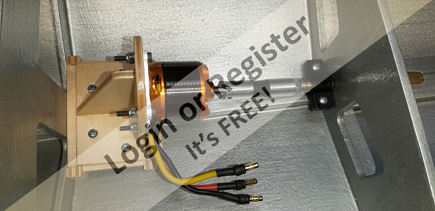
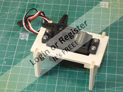
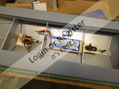
Now that I have the brushless motor I can assemble the motor mount that is supplied with the kit, the parts for this all slot together nicely and make quite a sturdy mount that has some adjustability for motor height and axial position. Using the alignment tool that I bought from ModelBoatBits along with the heavy duty flexible coupling I was able to fix the motor mount to the inner keel and bulkhead and line up the motor shaft and propshaft perfectly.
Before epoxying the propshaft tube in place the tube was drilled for the propshaft oiler which is a simple plastic ‘clamp’ type. The adjustment provided by the motor mount makes the final alignment of the shaft really quick and simple and this was left in place until the epoxy glue had set. The alignment piece will later be removed and replaced with the heavy duty flexible coupling which is dimensionally identical. The propshaft oiler will have a neoprene tube connected to it for easy access.
The hull was then given its final coat of finishing resin and then given a very thorough rub down with a 400 grit wet & dry paper used wet to polish the epoxy to a very fine finish ready for the primer coat.


They both needed a bit of light trimming to conform to the top rubbing strake and before fixing them to the hull I gave them both a couple of coats of Z-Poxy finishing resin on the exposed faces with a rub down in between.
Using them as a template, the outline of these pieces was drawn on the hull sides because I decided to fix them to the hull using dots of superglue applied progressively to the marked areas of the hull from stern to bow rather than using epoxy glue which would tend to ooze out and need cleaning off to restore the sharp outlines of the parts. This process worked really well and the lattices went on perfectly flat with no gaps.
There are some additional small pieces that are applied to the stern and these were fixed with a light smear of epoxy resin after carefully measuring and marking their positions, the epoxy allowed for some minor adjustment of these small parts so that they all spaced and lined up correctly and when set the surplus overlap was trimmed off.
The whole hull was then given a good rub down with a fine abrasive and then thoroughly cleaned with panel wipe to remove all dust and residue before the another coat of finishing resin was applied. This was done in five successive stages so that each ‘face’ could be kept as horizontal as possible to ensure that the resin didn’t produce any runs, the quick curing time of the resin allowed this to be done in one day.
Now that I have the brushless motor I can assemble the motor mount that is supplied with the kit, the parts for this all slot together nicely and make quite a sturdy mount that has some adjustability for motor height and axial position. Using the alignment tool that I bought from ModelBoatBits along with the heavy duty flexible coupling I was able to fix the motor mount to the inner keel and bulkhead and line up the motor shaft and propshaft perfectly.
Before epoxying the propshaft tube in place the tube was drilled for the propshaft oiler which is a simple plastic ‘clamp’ type. The adjustment provided by the motor mount makes the final alignment of the shaft really quick and simple and this was left in place until the epoxy glue had set. The alignment piece will later be removed and replaced with the heavy duty flexible coupling which is dimensionally identical. The propshaft oiler will have a neoprene tube connected to it for easy access.
The hull was then given its final coat of finishing resin and then given a very thorough rub down with a 400 grit wet & dry paper used wet to polish the epoxy to a very fine finish ready for the primer coat.
▲
⟩⟩
Scratchbuilder
Colin H
nasraf
Missouri
marky
hmsnostalgia
ianed57
Rookysailor
Joe727
MouldBuilder
mturpin013
RonH
RNinMunich
Skydive130
Martin555
|
💬 Re: Finishing the Hull.
4 years ago by 🇬🇧 hmsnostalgia (
Petty Officer 1st Class)✧ 99 Views · 1 Like
Flag
Petfectionist/ masochist ..... either way admiration & respect !!. 👍😀
▲
⟩⟩
robbob
|
|
Login To
Remove Ads 💬 Re: Finishing the Hull.
4 years ago by 🇬🇧 marky (
Commodore)✧ 100 Views · 2 Likes
Flag
Great job Rob .
Cheers Marky👍 ▲
⟩⟩
Missouri
Martin555
|
|
💬 Re: Finishing the Hull.
4 years ago by 🇬🇧 robbob (
Admiral)✧ 100 Views · 2 Likes
Flag
Hi hmsnostalgia.
Thanks for your kind words 👍😊 The problem is that being as meticulous as possible means that simple things take so much longer and complex things take forever!😉 Robbob. ▲
⟩⟩
hmsnostalgia
Missouri
|
|
💬 Re: Finishing the Hull.
4 years ago by 🇬🇧 hmsnostalgia (
Petty Officer 1st Class)✧ 100 Views · 2 Likes
Flag
I echo that sentiment, I am continually amazed at Robs attention to detail and painstaking effort to achieve the best possible finish to each part of the build process, this DEFINATELY shows in the final result !!. 👍😍👏👌
▲
⟩⟩
robbob
Missouri
|
|
💬 Re: Finishing the Hull.
4 years ago by 🇬🇧 robbob (
Admiral)✧ 100 Views · 3 Likes
Flag
Hi Pete.
Yes, the hull interior is painted with silver Hammerite, it gives an easy to clean hard wearing finish. The oiler is plastic and yes, it is the right way up 😀 Robbob. ▲
⟩⟩
Rookysailor
Missouri
Martin555
|
|
💬 Re: Finishing the Hull.
4 years ago by 🇬🇧 Rookysailor (
Commodore)✧ 100 Views · 3 Likes
Flag
Great build yet again Rob, is the interior painted with Hammerite? lovely finish👍
Cheers, Pete btw, Is the oiler fitted upside down? looks different to mine, but both black plastic I presume.🙄 ▲
⟩⟩
Missouri
Martin555
robbob
|
|
💬 Re: Finishing the Hull.
4 years ago by 🇬🇧 robbob (
Admiral)✧ 100 Views · 3 Likes
Flag
Hi Sy.
The oiler is quite a nice little thing, thanks for the heads up on that 👍, it fits my 8mm tube quite firmly but i'll probably add some ptfe tape to the tube before final fitting to ensure a good seal. Not expensive at all but second class delivery was about 10 days from the supplier 😮 I nearly gave up waiting and was about to order one from my usual source. Rob. ▲
⟩⟩
Colin H
Missouri
Martin555
|
|
💬 Re: Finishing the Hull.
4 years ago by 🇬🇧 robbob (
Admiral)✧ 100 Views · 4 Likes
Flag
Hi Mike.
Thanks for your praise. The rubber fenders are a neoprene foam 'D' profile, 10mm for the one that goes around the hull at deck level and 6mm over all of the area of the 'lattice' side frames. I've done a little test piece and it looks really effective. The foam has a hard(ish) outer skin and a closed cell interior so it's ideal for a wet environment. At the moment I'm working on the new cabin structure and it's coming along quite well, here's a sneak preview 😉. Credit due to Skydive130 for the inspiration 👍. Rob. 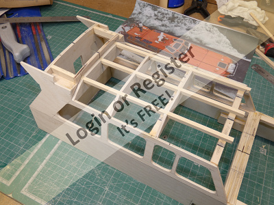
▲
⟩⟩
Colin H
Missouri
hmsnostalgia
Martin555
|
|
💬 Re: Finishing the Hull.
4 years ago by 🇬🇧 mturpin013 (
Admiral)✧ 100 Views · 3 Likes
Flag
Thats looking really nice Rob, up to your usual high standard. What are you using for the rubber?
▲
⟩⟩
Missouri
Martin555
robbob
|
|
💬 Re: Finishing the Hull.
4 years ago by 🇺🇸 RonH (
Chief Petty Officer 1st Class)✧ 116 Views · 3 Likes
Flag
What a great job, boat looks great and the silver interior looks great!
▲
⟩⟩
Missouri
hmsnostalgia
Martin555
|
|
💬 Re: Finishing the Hull.
4 years ago by 🇬🇧 Skydive130 (
Rear Admiral)✧ 100 Views · 2 Likes
Flag
Very nice oiler tube Rob 👍😂👍😂
▲
⟩⟩
Missouri
robbob
|
|
💬 Re: Finishing the Hull.
4 years ago by 🇬🇧 Martin555 (
Fleet Admiral)✧ 100 Views · 1 Like
Flag
Nice work Rob,
The silver painted interior certainly makes it look nice and neat. super work keep it up. Martin555. ▲
⟩⟩
Missouri
|
📝 Water Cooling and Rudder.
4 years ago by 🇬🇧 robbob ( Admiral)
Admiral)✧ 106 Views · 9 Likes · 7 Comments
Flag
💬 Add Comment
The hull is in pretty good shape now and almost ready for painting but before I start that I need to fit a water cooling pickup and outlet and the rudder tube.
I did buy a cheap two piece plastic set that I’ve used before but I chose again to call upon the expertise of my brother and his lathe to turn a brass base for a water pickup tube similar to one that he made for me when I did my Crash Tender model;
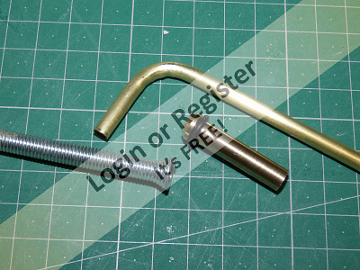
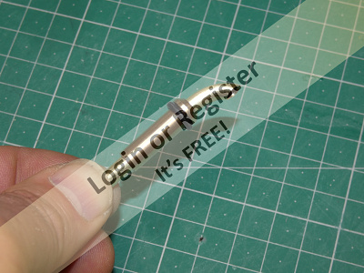
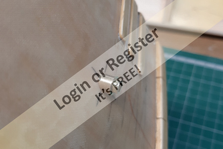

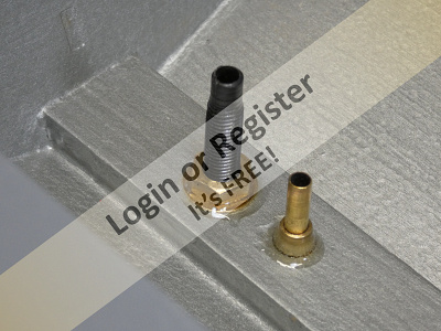
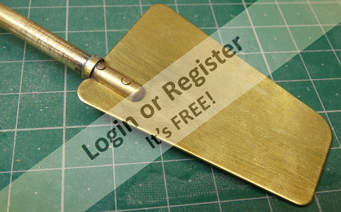
I did buy a cheap two piece plastic set that I’ve used before but I chose again to call upon the expertise of my brother and his lathe to turn a brass base for a water pickup tube similar to one that he made for me when I did my Crash Tender model;
▲
⟩⟩
Joe727
Missouri
Rookysailor
MouldBuilder
Colin H
ianed57
marky
Graham93
RonH
|
💬 Re: Water Cooling and Rudder.
4 years ago by 🇬🇧 robbob (
Admiral)✧ 100 Views · 2 Likes
Flag
Hi Sy.
All good tips deserve mention! BTW. The new cabin is just about finished now so I'll be blogging it soon. 😁 Rob. ▲
⟩⟩
Missouri
Martin555
|
|
Login To
Remove Ads 💬 Re: Water Cooling and Rudder.
4 years ago by 🇬🇧 Skydive130 (
Rear Admiral)✧ 100 Views · 4 Likes
Flag
Very nice cooling pipe work Rob, your Brother could make a little extra cash if he was to sell his superb services. Oh, and many thanks for mentioning my tip on the rudder, very decent of you 👍👍👍
▲
⟩⟩
alan50
Missouri
robbob
Martin555
|
|
💬 Re: Water Cooling and Rudder.
4 years ago by 🇬🇧 robbob (
Admiral)✧ 100 Views · 1 Like
Flag
Hi Bill.
Thanks for your kind words. The new cabin will be 'scratchbuilt' so that should be of interest to you 👍😆 Rob. ▲
⟩⟩
Missouri
|
|
💬 Re: Water Cooling and Rudder.
4 years ago by 🇬🇧 Scratchbuilder (
Vice Admiral)✧ 100 Views · 3 Likes
Flag
Hi Rob.
Excellent and precise work on all counts. Well done Bill 👍 ▲
⟩⟩
Missouri
robbob
Martin555
|
|
💬 Re: Water Cooling and Rudder.
4 years ago by 🇬🇧 Martin555 (
Fleet Admiral)✧ 100 Views · 2 Likes
Flag
Hi Robbob,
It is good to post the boring bit's as well as the good bits, As it helps the new guys and girls to this hobby to see what making a model boat is all about. Keep up the good work. Martin555. ▲
⟩⟩
MouldBuilder
Colin H
|
|
💬 Re: Water Cooling and Rudder.
4 years ago by 🇬🇧 robbob (
Admiral)✧ 100 Views · 3 Likes
Flag
Hi Martin.
The next instalment won't be too exciting I'm afraid, just the painting of the hull and deck and making up the servo mount and battery tray. After that it's the new cabin.......hooray I hear you say 🎉💥😆. Worth doing but a right pain in the !#*e 😉 but so much better than the kit version. Rob. ▲
⟩⟩
Missouri
Colin H
Martin555
|
|
💬 Re: Water Cooling and Rudder.
4 years ago by 🇬🇧 Martin555 (
Fleet Admiral)✧ 101 Views · 3 Likes
Flag
Hi Robob,
It is very handy having a brother that has a lathe. I still cannot get over how nice and neat that silver paint makes the inside look. Good work. I am looking forward to the next instalment. Martin555. ▲
⟩⟩
Missouri
Colin H
marky
|
📝 Priming the Hull and assembling the battery tray & servo mount.
4 years ago by 🇬🇧 robbob ( Admiral)
Admiral)✧ 106 Views · 10 Likes · 13 Comments
Flag
💬 Add Comment
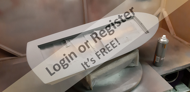
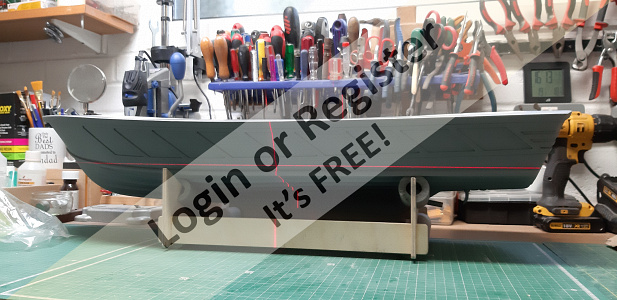
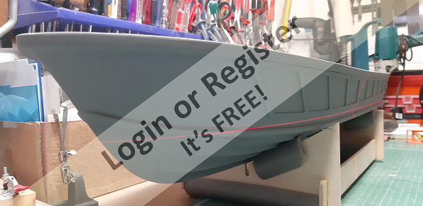
The hull is now ready for its primer coats so I masked off the deck opening, plugged the prop tube and water connections and then gave the whole thing a last rub down with some very fine abrasive paper and then really good clean with some panel wipe and a tack cloth.
It’s surprising how much residual dust a tack cloth will pick up!! 😮
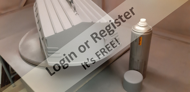
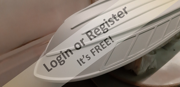
Starting with the deck I sprayed a first coat of Halfords grey primer and when that had flashed off I inverted the hull and sprayed the rest, this is where the turntable in the spray booth proves its worth!😁
After about 30 minutes the hull got a second coat of primer and when that had flashed off the deck got a second coat too.
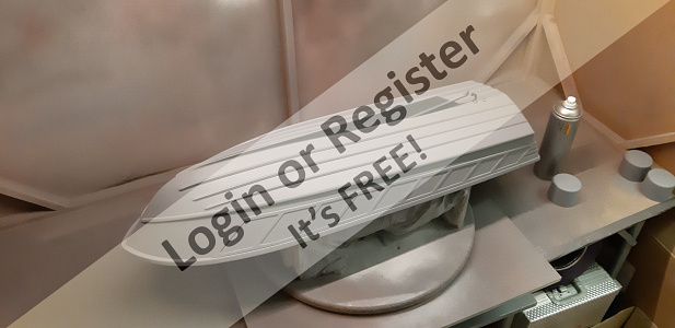
Pretty soon I’ll need to determine the waterline so that I can paint the red oxide ‘ anti fouling’ and the rest of the hull black but I don’t really want to do that yet until I have all of the heavy stuff like the batteries and all running gear on board, and most importantly, the new cabin which will be a little bit heavier than the standard kit version .
But just for now I decided to get out my self-levelling laser to get a rough idea where the waterline might cross the chines.
When I am able to do so I’ll do a float test in the bath and mark the hull at the waterline and decide if I need to allow for some ballast. I might cheat the waterline by ballasting so that it crosses the chine where I want it to for the shortest 'crossover' 😜
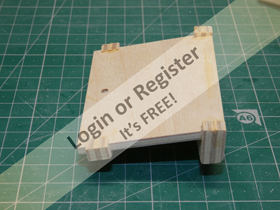
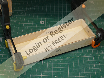
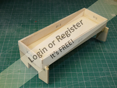
Meanwhile I can crack on and put together the battery tray and servo mount.
These two items are supplied in the kit and like the motor mount simply slot together with a bit of aliphatic glue to hold it all together.
A couple of coats of sanding sealer finishes them off nicely and I think I might leave them unpainted.
Now on to the new cabin.....👍😀
It’s surprising how much residual dust a tack cloth will pick up!! 😮
Starting with the deck I sprayed a first coat of Halfords grey primer and when that had flashed off I inverted the hull and sprayed the rest, this is where the turntable in the spray booth proves its worth!😁
After about 30 minutes the hull got a second coat of primer and when that had flashed off the deck got a second coat too.
Pretty soon I’ll need to determine the waterline so that I can paint the red oxide ‘ anti fouling’ and the rest of the hull black but I don’t really want to do that yet until I have all of the heavy stuff like the batteries and all running gear on board, and most importantly, the new cabin which will be a little bit heavier than the standard kit version .
But just for now I decided to get out my self-levelling laser to get a rough idea where the waterline might cross the chines.
When I am able to do so I’ll do a float test in the bath and mark the hull at the waterline and decide if I need to allow for some ballast. I might cheat the waterline by ballasting so that it crosses the chine where I want it to for the shortest 'crossover' 😜
Meanwhile I can crack on and put together the battery tray and servo mount.
These two items are supplied in the kit and like the motor mount simply slot together with a bit of aliphatic glue to hold it all together.
A couple of coats of sanding sealer finishes them off nicely and I think I might leave them unpainted.
Now on to the new cabin.....👍😀
▲
⟩⟩
ChrisB
MouldBuilder
Missouri
Rookysailor
RonH
ianed57
Joe727
marky
Martin555
Skydive130
|
💬 Re: Priming the Hull and assembling the battery tray & servo mount.
4 years ago by 🇬🇧 octman (
 Chief Petty Officer 2nd Class) Chief Petty Officer 2nd Class)✧ 105 Views · 1 Like
Flag
or even a "should have" moment!
▲
⟩⟩
Martin555
|
|
Login To
Remove Ads 💬 Re: Priming the Hull and assembling the battery tray & servo mount.
4 years ago by 🇬🇧 Rookysailor (
Commodore)✧ 101 Views · 3 Likes
Flag
At £9.99 Rob, the answer is possibly, might be, maybe...........NO!👎
Cheers, Pete ▲
⟩⟩
marky
Missouri
Martin555
|
|
💬 Re: Priming the Hull and assembling the battery tray & servo mount.
4 years ago by 🇬🇧 robbob (
Admiral)✧ 100 Views · 2 Likes
Flag
Ahh.....but is it self-levelling? 🤔
Rob. ▲
⟩⟩
Missouri
Martin555
|
|
💬 Re: Priming the Hull and assembling the battery tray & servo mount.
4 years ago by 🇬🇧 Rookysailor (
Commodore)✧ 100 Views · 3 Likes
Flag
Lovely laser level Rob, but of course Bosch one of the best, photo of a laser level I bought from one of the boat shows last year, nowhere near the quality of yours, but at a cost of £9.99, and it works.👍
Cheers, Pete 

▲
⟩⟩
Missouri
Martin555
robbob
|
|
💬 Re: Priming the Hull and assembling the battery tray & servo mount.
4 years ago by 🇬🇧 robbob (
Admiral)✧ 100 Views · 2 Likes
Flag
Hi Neil.
To the best of my knowledge all modern servos operate on the same principle and are universally interchangeable regardless or brand or make. A digital transmitter is usually a 2.4 GHz unit with a computer 'brain' that allows the user to programme various functions and even old servos are compatible with them. Rob. ▲
⟩⟩
Missouri
Martin555
|
|
💬 Re: Priming the Hull and assembling the battery tray & servo mount.
4 years ago by 🇬🇧 neilmc (
 Warrant Officer) Warrant Officer)✧ 100 Views · 2 Likes
Flag
Well thats another couple of photos for my 'how to do it' album another excellent update on fantastic build blog.
Can the futaba servo be used with a digital transmitter? ▲
⟩⟩
Missouri
Martin555
|
|
💬 Re: Priming the Hull and assembling the battery tray & servo mount.
4 years ago by 🇬🇧 Rookysailor (
Commodore)✧ 100 Views · 2 Likes
Flag
Beautiful finish on the hull Rob, have to agree with
Martin, servo mount and battery tray, would look much better painted with the same paint as the hull interior👍 but as you say, can always update it😊 Cheers, Pete ▲
⟩⟩
Missouri
Martin555
|
|
💬 Re: Priming the Hull and assembling the battery tray & servo mount.
4 years ago by 🇬🇧 robbob (
Admiral)✧ 101 Views · 4 Likes
Flag
Hi Joe.
If I remember correctly my kids clubbed together and got it for me for Fathers Day after they asked what I'd like. There are cheaper alternatives though. Lidl in the UK have their own 'Parkside' brand and were selling one almost identical in UK stores late last year, at about half the price of the Bosch one. Problem is you never know when they will put them out for sale 😠 Rob. 
▲
⟩⟩
Rookysailor
Missouri
MouldBuilder
Martin555
|
|
💬 Re: Priming the Hull and assembling the battery tray & servo mount.
4 years ago by 🇺🇸 Joe727 (
Commander)✧ 100 Views · 3 Likes
Flag
Rob,
I have been considering buying a laser level but haven't pulled the trigger yet. Have not known what to buy so I looked up the Bosch in your photo and see that it is NOT sold in the US yet. Will have to keep looking for one that suits my needs. Thank for the interesting posts and as usual the great photos! 👍 Joe ▲
⟩⟩
Missouri
robbob
Martin555
|
|
💬 Re: Priming the Hull and assembling the battery tray & servo mount.
4 years ago by 🇬🇧 robbob (
Admiral)✧ 100 Views · 2 Likes
Flag
Hi Martin.
None of them are permanently fixed into the boat so if I have a change of heart it's not a problem to take them out and paint them 😎 Rob. ▲
⟩⟩
Missouri
Martin555
|
|
💬 Re: Priming the Hull and assembling the battery tray & servo mount.
4 years ago by 🇬🇧 Martin555 (
Fleet Admiral)✧ 100 Views · 1 Like
Flag
Hi Robbob,
You are doing a great job. I personally think the Battery, servo and motor mounts should be painted. It would save that " I should of " moment. Martin555. ▲
⟩⟩
Missouri
|
|
Login To
Remove Ads 💬 Re: Priming the Hull and assembling the battery tray & servo mount.
4 years ago by 🇬🇧 robbob (
Admiral)✧ 101 Views · 3 Likes
Flag
Hi Sy.
It's made by Bosch and was not cheap but it's proved to be so useful, not just for my model making but for general DIY, great for marking out levels when tiling a bathroom for instance. Rob. 
▲
⟩⟩
MouldBuilder
Joe727
Martin555
|
|
💬 Re: Priming the Hull and assembling the battery tray & servo mount.
4 years ago by 🇬🇧 Skydive130 (
Rear Admiral)✧ 101 Views · 5 Likes
Flag
Rob, that laser level seems like the “muts nuts”, saves gluing a pencil to a scrap piece of wood and trying to scribe a waterline. Can you give me some more details on it as it looks like a great investment 👌cheers, Sy
▲
⟩⟩
CalebS-L
Missouri
Joe727
Martin555
robbob
|


Login To
Remove Ads
Remove Ads