Join Us On Social Media!

|

|

|
Download The App!
Login To
Remove Ads
Remove Ads
Login To
Remove Ads
Remove Ads
Model Boats Website
USS Fletcher DD-445
12 Posts · 10 Followers · 120 Photos · 74 Likes
Began 3 years ago by
 United States
Follow This Thread
Not currently following
> Click to follow
> Click to follow
Latest Post 2 years ago by
| Oldest posts shown first (Show Newest First) | (Print Booklet) |
📝 USS Fletcher DD-445
3 years ago by 🇺🇸 ToraDog ( Captain)
Captain)✧ 115 Views · 7 Likes · 3 Comments
Flag
💬 Add Comment
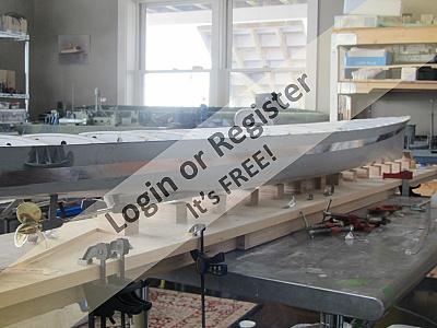
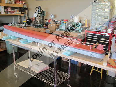
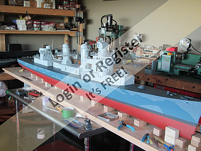
Well, while I have been laying low since finishing the USCGC Eastwind, I have not been idle. I actually started this build about a year and a half ago. Like the Eastwind and the majority of my fleet, she is in 1/48th scale so she is a little over seven feet.
Quite a few years back I bought a second hand 1/48th Fletcher hull which I built into the USS Halford, DD-480, one of three Fletchers which mounted catapults and OS2U Kingfisher float planes. She came out pretty well. Later I was offered 3 1/48 USN destroyer hulls, another Fletcher, a Sumner, and a Gearing. I gave the Sumner and the Gearing to friends and kept the Fletcher. I had decided that I wanted to try to build the name ship of the class, as she was commissioned. I need to point out that, as commissioned, lasted only until she had completed her shakedown trials, after which she entered the New York Navy Yard and her appearance began to change. As such, she is modeled to represent a period of about a month of her life, which ran from 1942 to 1972 when she was sold and broken up for scrap. I will not go into her history, except to say that she was in the thick of the Southwest Pacific campaign from Guadalcanal right thru to Vietnam. She was the first of 175 ships in her class. The fastest recorded build of one of her class was 90 days, from keel laying to commissioning, built by Bath Iron Works, Bath, Maine. Her functions, to date, are independent motors, rudder, smoke from both stacks, independent search lights, independent control of turrets and gun director with the ability to mix as needed, torpedo tubes, and some sound systems as well as radar and sonar.
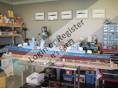
To date she has passed her trials and is awaiting the placement of stanchions and wire ropes, which I hope to finish this year.
Her radio system uses telemetry so I can read her running voltage and amperage. I know her lat/long( like I need that!), and her speed in knots. She does not quite make the true 39+ knots that she did on trials, rather about 36, which is quite fast in her scale as it is. When I compared trial photos of the original to my model, they had almost the exact same bow waves and wake patterns. I was happy.
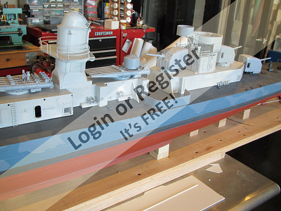
Here is the Fletcher on trials. This is the image that I am aiming to achieve. I will start the build blog in a day or so. Enjoy and I will entertain all queries.


Quite a few years back I bought a second hand 1/48th Fletcher hull which I built into the USS Halford, DD-480, one of three Fletchers which mounted catapults and OS2U Kingfisher float planes. She came out pretty well. Later I was offered 3 1/48 USN destroyer hulls, another Fletcher, a Sumner, and a Gearing. I gave the Sumner and the Gearing to friends and kept the Fletcher. I had decided that I wanted to try to build the name ship of the class, as she was commissioned. I need to point out that, as commissioned, lasted only until she had completed her shakedown trials, after which she entered the New York Navy Yard and her appearance began to change. As such, she is modeled to represent a period of about a month of her life, which ran from 1942 to 1972 when she was sold and broken up for scrap. I will not go into her history, except to say that she was in the thick of the Southwest Pacific campaign from Guadalcanal right thru to Vietnam. She was the first of 175 ships in her class. The fastest recorded build of one of her class was 90 days, from keel laying to commissioning, built by Bath Iron Works, Bath, Maine. Her functions, to date, are independent motors, rudder, smoke from both stacks, independent search lights, independent control of turrets and gun director with the ability to mix as needed, torpedo tubes, and some sound systems as well as radar and sonar.
To date she has passed her trials and is awaiting the placement of stanchions and wire ropes, which I hope to finish this year.
Her radio system uses telemetry so I can read her running voltage and amperage. I know her lat/long( like I need that!), and her speed in knots. She does not quite make the true 39+ knots that she did on trials, rather about 36, which is quite fast in her scale as it is. When I compared trial photos of the original to my model, they had almost the exact same bow waves and wake patterns. I was happy.
Here is the Fletcher on trials. This is the image that I am aiming to achieve. I will start the build blog in a day or so. Enjoy and I will entertain all queries.
▲
⟩⟩
hermank
RNinMunich
Colin H
stevedownunder
Rookysailor
Nerys
Newby7
|
💬 Re: USS Fletcher DD-445
3 years ago by 🇬🇧 camyaj (
 Petty Officer 2nd Class) Petty Officer 2nd Class)✧ 116 Views · 2 Likes
Flag
My Favourite Fletcher story
▲
⟩⟩
RNinMunich
Rookysailor
|

|
Login To
Remove Ads 💬 Re: USS Fletcher DD-445
3 years ago by 🇬🇧 Nerys (
 Fleet Admiral) Fleet Admiral)✧ 121 Views · 0 Likes
Flag
If nothing else, your dedication to the Fletcher class is to be admired but I think you have built a remarkable model. Very well done.
Nerys ▲
⟩⟩
No likes yet
This member will receive 1 point for every like received |
|
💬 Re: USS Fletcher DD-445
3 years ago by 🇨🇦 Newby7 (
Fleet Admiral)✧ 115 Views · 0 Likes
Flag
I look forward to see this build blog.
Rick ▲
⟩⟩
No likes yet
This member will receive 1 point for every like received |
Login To
Remove Ads
Remove Ads
📝 Fletcher
3 years ago by 🇺🇸 ToraDog ( Captain)
Captain)✧ 119 Views · 7 Likes · 3 Comments
Flag
💬 Add Comment
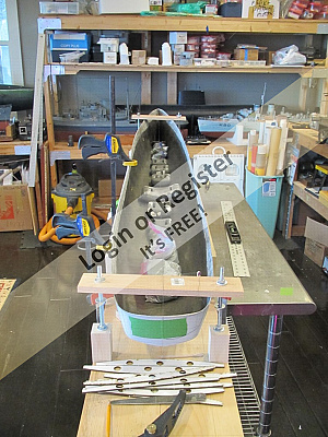
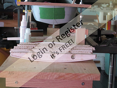
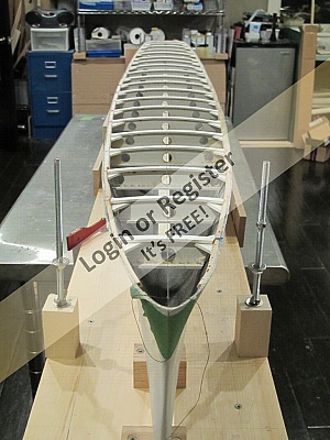
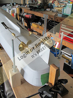
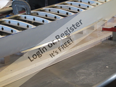
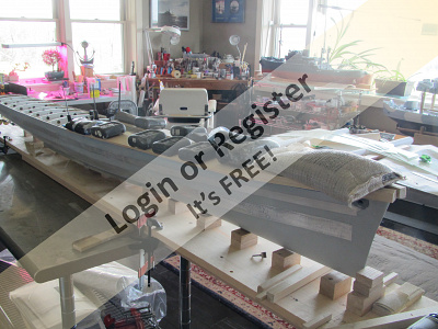
My builds start with a build board long enough to accommodate the hull with plenty of room off the ends for supports and "stuff". I add runners to the bottom of the board for stiffness and draw a center line and station lines on the top of the board. These help me to align the hull and check it for trueness. I add a few vertical braces to the sides of the hull to hold it upright and centered on the board. These also help me to define and maintain a level deck line. I was taught that the hull needs to be braced with deck beams, which define and hold the the shape of the hull deck line and much of the sides of the hull. They provide great stiffness to the hull. After they have been installed, I was taught, one can install the shaft logs, rudder tube/s, and bilge keels without worrying that flexing of the hull will interfere with any of the afore mentioned.
So.. I mounted my hull, all 94.416 inches of her, onto my board and leveled her side to side amidships and at the bow. Here I ran into my first problem. The stern was twisted by almost an inch. On carefully examine I found that the turn of one bilge was not anywhere near the tun of the opposite bilge. And, the skeg was off center. I bought this hull many years back and stored it with it's other two mates. I don't know if the hull was poorly manufactured, or if in storage over the years it took a set, or a combination of both. I had built the same hull before and not had this issue,, so I tend to lean towards time and storage as the issue. Anyhow... It took me a while to figure out how to proceed. Ultimately I added strong back sides to my build board. These defined the beam of the hull. I then came up with a clamp system to hold the hull in place while slowly forcing the twist out of the hull. I also added cleat to the skeg to hold it in alignment with the keel centerline on the build board. I knew, at this point, that if I simply added deck beams they would be put under severe tension when I released my clamps. Also, they would not address the issue of the turn of the Starboard bilge being so flat. I remembered that somewhere I had heard or read that heat will cause polyester hulls to re-shape. I did not think I had anything to lose because this hull was not usable in its current condition. I got out my heat gun! Before I hit the hull with heat I added as much lead to the keel line as I could muster, about 100 lbs. Then cam the heat. Gradually I could hear and see the hull relax and settle into place. A few adjustments of my screw clamps and more heat and she was there. I let her cool completely and checked her measurements and her levels REALLY carefully. She looked good. This whole affair took about two weeks. Her skeg was even settled on center line, but it proved to be a bit asymetrical. Nothing to worry about, because that could be addressed later. Next up was to add beams just below the deck edges and then add he deck beams. She remained clamped to the the build board throughout both of these build sections so as to maintain he shape. It seems to work well, because when all was said and done, beams in place and clamps removed, her measurements were spot on, twist was gone, she was straight and rigid.
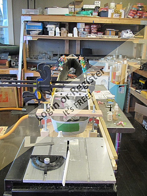
So.. I mounted my hull, all 94.416 inches of her, onto my board and leveled her side to side amidships and at the bow. Here I ran into my first problem. The stern was twisted by almost an inch. On carefully examine I found that the turn of one bilge was not anywhere near the tun of the opposite bilge. And, the skeg was off center. I bought this hull many years back and stored it with it's other two mates. I don't know if the hull was poorly manufactured, or if in storage over the years it took a set, or a combination of both. I had built the same hull before and not had this issue,, so I tend to lean towards time and storage as the issue. Anyhow... It took me a while to figure out how to proceed. Ultimately I added strong back sides to my build board. These defined the beam of the hull. I then came up with a clamp system to hold the hull in place while slowly forcing the twist out of the hull. I also added cleat to the skeg to hold it in alignment with the keel centerline on the build board. I knew, at this point, that if I simply added deck beams they would be put under severe tension when I released my clamps. Also, they would not address the issue of the turn of the Starboard bilge being so flat. I remembered that somewhere I had heard or read that heat will cause polyester hulls to re-shape. I did not think I had anything to lose because this hull was not usable in its current condition. I got out my heat gun! Before I hit the hull with heat I added as much lead to the keel line as I could muster, about 100 lbs. Then cam the heat. Gradually I could hear and see the hull relax and settle into place. A few adjustments of my screw clamps and more heat and she was there. I let her cool completely and checked her measurements and her levels REALLY carefully. She looked good. This whole affair took about two weeks. Her skeg was even settled on center line, but it proved to be a bit asymetrical. Nothing to worry about, because that could be addressed later. Next up was to add beams just below the deck edges and then add he deck beams. She remained clamped to the the build board throughout both of these build sections so as to maintain he shape. It seems to work well, because when all was said and done, beams in place and clamps removed, her measurements were spot on, twist was gone, she was straight and rigid.
▲
⟩⟩
hermank
RNinMunich
Colin H
stevedownunder
jbkiwi
Black Shoe
Newby7
|
💬 Re: Fletcher
3 years ago by 🇦🇺 stevedownunder (
Captain)✧ 114 Views · 0 Likes
Flag
Hi ToraDog,
That is one big model, that cannot have been a happy moment when you discovered the warp. Great solution for straitening the hull. Cheers, Stephen. ▲
⟩⟩
No likes yet
This member will receive 1 point for every like received |
|
Login To
Remove Ads 💬 Re: Fletcher
3 years ago by 🇺🇸 ToraDog (
Captain)✧ 119 Views · 1 Like
Flag
Rick,
Fortunately she does not tip the scales quite THAT badly. The weight you see in my posts were there to help re-mould the hull to shape. In actuality my ballast consists of two 12 amp SLA batteries and about 4 lbs of lead for trim. I'll expound upon that later. I launch her by clamping a set of frame mounted bicycle tires to the build board and roll her into the lake. I will add photos as well later. ▲
⟩⟩
stevedownunder
|
|
💬 Re: Fletcher
3 years ago by 🇨🇦 Newby7 (
Fleet Admiral)✧ 119 Views · 1 Like
Flag
The write up for how you went about fixing the hull was well done. I do look to follow your build. Must ask how you get your finished boats to the water. From your post you have a 100 lb of lead in the keel do you have an idea on how much ballast or where to place the weight. What might the finished weight be.
Rick ▲
⟩⟩
stevedownunder
|
📝 Fletcher
3 years ago by 🇺🇸 ToraDog ( Captain)
Captain)✧ 133 Views · 6 Likes · 7 Comments
Flag
💬 Add Comment
I am going to detour a bit today and talk about materials and "new" stuff......
First materials, most, if not all, of my superstructures and houses I now build from PVC Sheet. Called "sign board" over here, it is an expanded PVC sheet material that has two finished faces. It is available from any number of sources in any number of thicknesses and sheet sizes. Mostly I use 1/8th inch(.125). Many folk use thinner, but I like the thickness for the added rigidity. It can be thermo-formed with a heat gun. The finished surfaces are paint ready. They do not need to be sanded, not primed, although I do to cover up the putty I use to hide my "perfect" gaps, on occasion🙄. This material LOVES CA. No accelerator needed. And It is light. Even though I build in 1/48th scale, top weight can be an issue and this material make life much easier. It cuts easily with an Xacto knife and drills like butter. Care should be taken because high speeds will melt it! I also used this material for my deck beams. I assembled them with CA, tacked them into place in the hull with CA, and then bonded them into place with thickened epoxy. When the deck was attached to them, epoxy was used again. More on that later.
New Stuff: On each successive build I try to incorporate something new. Some technique or mechanical system that I have never tried, or dared to try before. With the Fletcher I have done several things which will be highlighted in turn during the build, such as functional caged house lights. I also made the great leap. I know, why did it take so long....Well mostly because I had so many great Robbe 75 mhz radios, actually I am kinda' old school and my other half refers to me a stubborn. If she only knew... BUT, I bought my first 2.4ghz radio for the Fletcher. In doing so I entered the realm of true computer radios(way over my head) and took the bait, hook, line and sinker. Fletcher will benefit from enhanced scale functions, ie gun movement, mixing of functions, speed adjustments ect. I will benefit from telemetry( as soon as I figure out what it is, what it does, and why I bothered)😂 At this point I will jump ahead and tell you that after consulting the scale speed conversion charts and completing the maiden test voyage of the Fletcher, she did not measure up. Sadly she made only 36 knots rather that her true 39.4 knots. She has a GPS on board and it reported her speed. As it was, I and everyone else thought that she was going far over scale speed, when in fact she did not. After comparing photographs of her sister, the Nicholas, on trials off Rockland, Maine, to photographs of the Fletcher on the pond, I confirmed that her wave patterns VERY closely matched those of the Nicholas. OK, enough spoilers for now.
Next installment will continue with the deck beams install, shafts, bilge keels and rudder.
▲
⟩⟩
hermank
RNinMunich
Colin H
stevedownunder
Rookysailor
Newby7
|
💬 Re: Fletcher
3 years ago by 🇺🇸 ToraDog (
Captain)✧ 110 Views · 1 Like
Flag
Stephen,
Thank you for the link. Yes, I am running Open TX and YES it is a whole new world. I will get to it later in my build, but WOW, between OTX and GoBilda servos....the animation that one can perform is just wonderful. Thanks for the very kind comments Jonathan ▲
⟩⟩
stevedownunder
|
|
Login To
Remove Ads 💬 Re: Fletcher
3 years ago by 🇦🇺 stevedownunder (
Captain)✧ 109 Views · 1 Like
Flag
Hi ToraDog,
Nice radio, I have the Taranis 9X plus. Have you checked out Open TX, this is an open source program that allows you to program your radio using a pc or laptop it is an incredible bit of software and it is free. Here is a link if you are interested. https://www.open-tx.org Cheers, Stephen. ▲
⟩⟩
RNinMunich
|

|
💬 Re: Fletcher
3 years ago by 🇺🇸 ToraDog (
Captain)✧ 129 Views · 3 Likes
Flag
Steve,
I opted for the FrSky X9E tray radio. I am use to the Robbe F-14, so this was an easy move. What I found to be most attractive, is that, in addition to the 4 proportional channels on the two gimbals, there are 6 more proportional channels and up to 16 switches which can be assigned to channels or to activate mixing ect. It come with 8 switches( i believe) including an on/off momentary one that is assigned to the training (buddy box) circuit. It too can be reassigned. I will post some photos of it as well as my build board launch system, coming up. Pictures of her trials will be forth coming as well. 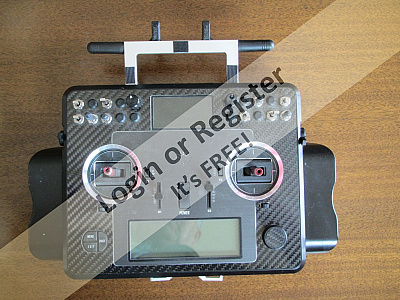
▲
⟩⟩
stevedownunder
sirscapa
Colin H
|
|
💬 Re: Fletcher
3 years ago by 🇦🇺 stevedownunder (
Captain)✧ 129 Views · 0 Likes
Flag
Hi ToraDog,
Love to see some on the water shots if possible. Which 2.4 ghz system did you go for? Cheers, Stephen. ▲
⟩⟩
No likes yet
This member will receive 1 point for every like received |
|
💬 Re: Fletcher
3 years ago by 🇺🇸 ToraDog (
Captain)✧ 131 Views · 2 Likes
Flag
Absolutely correct! That said I have found that the closer the scale moves toward 1:1, the easier it is to get the appearance of scale acting water. Of course... Fletchers did not run in fresh water either! 😂 I moved from 1/96th to 1/48 just for that reason. Ii could not stand my battleships bobbing like toy ducks in the pond. All my opinion, which frankly counts for zip.
▲
⟩⟩
Homdadream67
stevedownunder
|
|
💬 Re: Fletcher
3 years ago by 🇬🇧 mturpin013 (
 Admiral) Admiral)✧ 135 Views · 1 Like
Flag
Unfortunately scale speed will never be accomplished as long as your sailing in water.
You can't scale water! It will always unfortunately only be scale for real boats ▲
⟩⟩
stevedownunder
|
|
💬 Re: Fletcher
3 years ago by 🇨🇦 Newby7 (
Fleet Admiral)✧ 133 Views · 2 Likes
Flag
Stubborn you say can't believe that. I don't say stubborn I say determined. Wife may say something different. LOL
Rick ▲
⟩⟩
RNinMunich
stevedownunder
|
📝 Fletcher
3 years ago by 🇺🇸 ToraDog ( Captain)
Captain)✧ 130 Views · 7 Likes · 2 Comments
Flag
💬 Add Comment
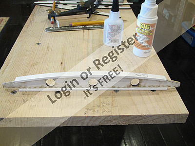
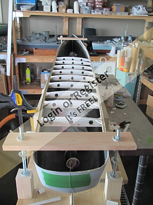
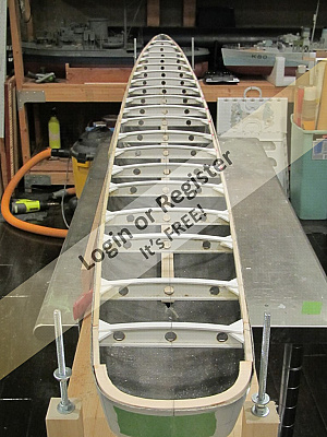
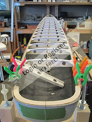
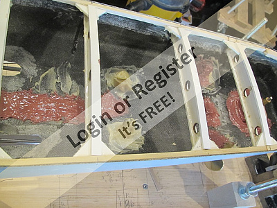
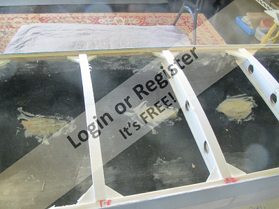
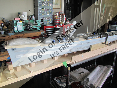
A couple of things that I failed to mention in my previous posts. 1) The expanded PVC board mills and cuts wonderfully by laser. In fact I had my deck beams lasered out by BlueJacket Shipfitters, which happens to be a few miles down the road from me. This accounts for the burn marks on my deck beams. I had lightening holes add which doubled for cable runs. As flat beams, they are not too rigid, but but CAing a cap and and a bottom them, they became curved top I beams and are very strong. The caps and bottoms I ripped out on my table saw.
My deck edge beams are 1/4" square basswood planed to correct angles where the bow flair kick in. I notched the bow and stern of the hull with a razor saw and taped a thread into the notches for my center line. This way I kept my beams centered, more or less. I cut out the stern deck edge and sanded it to fit.
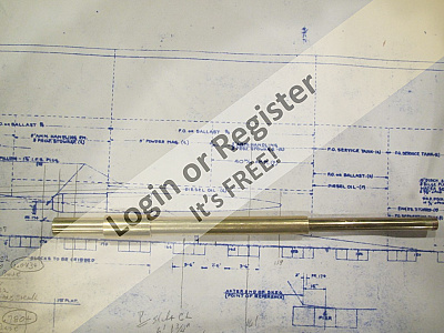
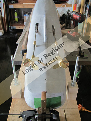
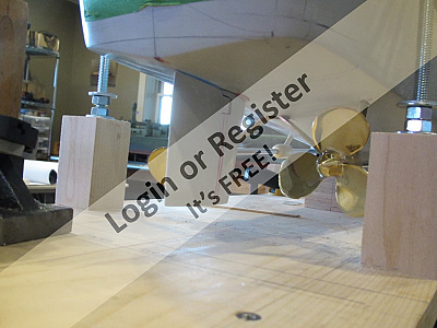
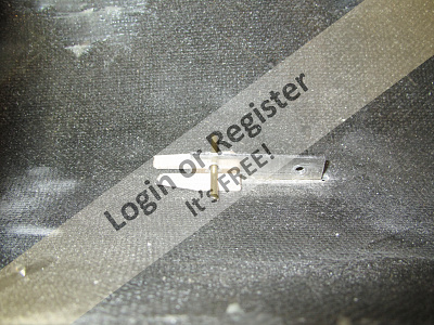
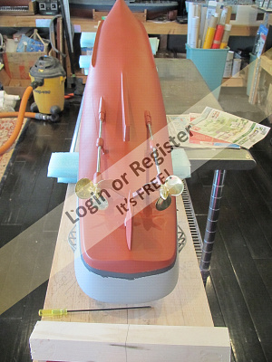
Next up were shafts and the rudder. The shafts, stuffing boxes, struts and props were made for me by George Sitek and I can not give him enough praise. George made my props special for me and they are just that, special. The shafts, when installed, run parallel to the keel, but do not share the same angle relative to the keel vertically. This is because USN alternated boiler and engine rooms. This put the two engine rooms significantly fore and aft of each other which in turn caused the differing shaft angles. I screwed this up on my first Fletcher build and was not going to do it again!
Because of the run of the shafts, I extended George's stuffing boxes with brass turning.
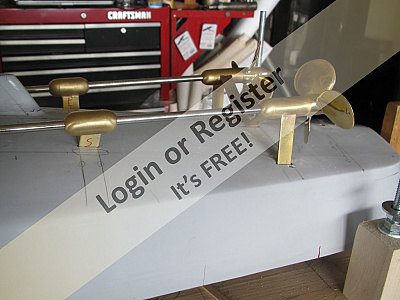
The struts installed in the normal way but I add some beef to them. Inboard of the hull I mark the struts and drilled holes thru them. One aligned and tacked into place, ready for thickened epoxy, I inserted brass rods thru the hole I had drilled and them epoxied the strut into place. They are not coming out easily and if I hit an object, ie, if my draft exceeds the depth of the water, I expect either no damage, or really serious damage.
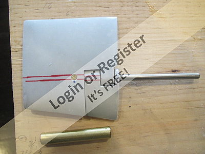
The rudder is a Scale Shipyard resin casting. Because of the way the USN mounts their rudders, it can be a bear to remove. I developed a system, probably done way before me, where by I drilled the rudder for the shaft, then cross drilled the rudder and shaft. I then tapped the shaft and one side of the rudder for a flat head machine screw. When put into place, only the slot of the machine screw is detectable.
Shafts, struts, and rudder were all bounded into the hull with thickened epoxy. My better half will not allow me to use polyester resin in the house.😭
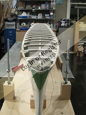
Next up I made some hawser pies from brass rod, annealed, bent and soldered. Epoxied into place. I then move to the propeller guards... I hate making these. Soldered up from square brass tube stock. While this was being done, my bilge keels were being cut for me by a blacksmith in town. They are aluminum, I believe 1/16" stock. I believe I am correct saying that bilge keels should run parallel to the ship's keel. As such plotting their location was done by measuring a set distance from the hull center line using a seamstress measuring tape. Fore and aft points of the BKs were plotted from the plans. Then it is a matter of connecting dots. My keels have tags built into them. The tangs extend into the hull and each had several hole drilled thru them. One the keel was taped into place, I inserted short sections of rod into each hole in the tangs. Then I made small wooden wedges that slid between the hull and the rods. When the wedges tightened, the tangs were drawn in and the keel snugged up firm to the hull. A liberal application of thickened epoxy and time and the keels were set. Like the strut, they are not going anywhere and all is very H2O tight.
The hull was now shaped, rigid, all thru hulls were in and she was watertight.


My deck edge beams are 1/4" square basswood planed to correct angles where the bow flair kick in. I notched the bow and stern of the hull with a razor saw and taped a thread into the notches for my center line. This way I kept my beams centered, more or less. I cut out the stern deck edge and sanded it to fit.
Next up were shafts and the rudder. The shafts, stuffing boxes, struts and props were made for me by George Sitek and I can not give him enough praise. George made my props special for me and they are just that, special. The shafts, when installed, run parallel to the keel, but do not share the same angle relative to the keel vertically. This is because USN alternated boiler and engine rooms. This put the two engine rooms significantly fore and aft of each other which in turn caused the differing shaft angles. I screwed this up on my first Fletcher build and was not going to do it again!
Because of the run of the shafts, I extended George's stuffing boxes with brass turning.
The struts installed in the normal way but I add some beef to them. Inboard of the hull I mark the struts and drilled holes thru them. One aligned and tacked into place, ready for thickened epoxy, I inserted brass rods thru the hole I had drilled and them epoxied the strut into place. They are not coming out easily and if I hit an object, ie, if my draft exceeds the depth of the water, I expect either no damage, or really serious damage.
The rudder is a Scale Shipyard resin casting. Because of the way the USN mounts their rudders, it can be a bear to remove. I developed a system, probably done way before me, where by I drilled the rudder for the shaft, then cross drilled the rudder and shaft. I then tapped the shaft and one side of the rudder for a flat head machine screw. When put into place, only the slot of the machine screw is detectable.
Shafts, struts, and rudder were all bounded into the hull with thickened epoxy. My better half will not allow me to use polyester resin in the house.😭
Next up I made some hawser pies from brass rod, annealed, bent and soldered. Epoxied into place. I then move to the propeller guards... I hate making these. Soldered up from square brass tube stock. While this was being done, my bilge keels were being cut for me by a blacksmith in town. They are aluminum, I believe 1/16" stock. I believe I am correct saying that bilge keels should run parallel to the ship's keel. As such plotting their location was done by measuring a set distance from the hull center line using a seamstress measuring tape. Fore and aft points of the BKs were plotted from the plans. Then it is a matter of connecting dots. My keels have tags built into them. The tangs extend into the hull and each had several hole drilled thru them. One the keel was taped into place, I inserted short sections of rod into each hole in the tangs. Then I made small wooden wedges that slid between the hull and the rods. When the wedges tightened, the tangs were drawn in and the keel snugged up firm to the hull. A liberal application of thickened epoxy and time and the keels were set. Like the strut, they are not going anywhere and all is very H2O tight.
The hull was now shaped, rigid, all thru hulls were in and she was watertight.
▲
⟩⟩
Rookysailor
RNinMunich
jbkiwi
stevedownunder
Colin H
mturpin013
Graham93
|
💬 Re: Fletcher
3 years ago by 🇩🇪 RNinMunich (
Fleet Admiral)✧ 117 Views · 1 Like
Flag
Veery interestink TD! (But don't forget to tell Lucy!😉)
I shall have to check that on my 144 scale kit! Cheers, Doug 😎 ▲
⟩⟩
Rookysailor
|
|
💬 Re: Fletcher
3 years ago by 🇦🇺 stevedownunder (
Captain)✧ 127 Views · 0 Likes
Flag
Lovely work ToraDog,
Interesting point well researched, I wonder how many Fletchers are out there with the shaft positions wrong quite a few I would think. Cheers, Stephen. ▲
⟩⟩
No likes yet
This member will receive 1 point for every like received |
📝 Fletcher
3 years ago by 🇺🇸 ToraDog ( Captain)
Captain)✧ 128 Views · 4 Likes
Flag
💬 Add Comment
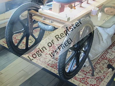
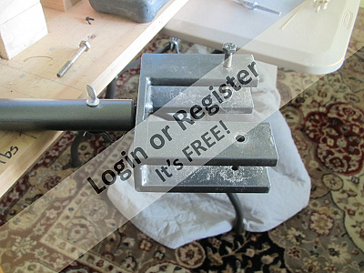
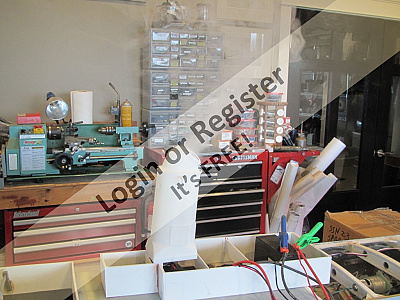
A quick post in reply to how I launch my beasts. As I had mentioned, I had a frame, made of steel C channel, made for me. On each leg are drill a series of holes for my axles.
The holes allow me to change the angle of the hull as is enters the water. More importantly, it allows for adjustment of the slope of the banking. I hate sinking my boats stern first...
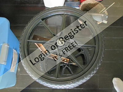
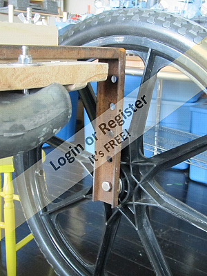
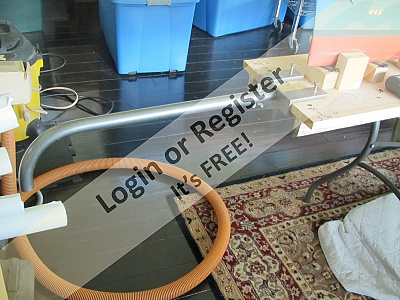
The C channel can either bolt to the underside of the build board, or, when engaging a cleat on the top of the board, be clamped into place. I have to add weight, in the form of dive weights, to the build board to compensate for the board and the wheels buoyancy. Again, they simply bolt to the board where needed. The wheels came from Amazon and the axles are 5/8" bolts.
Rather than kill my back anymore I had a handle made for the forward end of the board and it bolts to the board as the pictures show.
Putting it all together is easy. I get to the pond and slide the aft end of the board out of my van about 1-2 ft. After checking the pond slope, I adjust my wheel height and clamp/bolt my wheels into place. The board can now slide out and the wheels support the aft end on the ground. I grab the front, ease it out and bolt on the handle. That is it. Sounds much worse than it is.
The wheel frame and handle fit onto all of my build boards of nay size. My Corvette doesn't need it.😂


The holes allow me to change the angle of the hull as is enters the water. More importantly, it allows for adjustment of the slope of the banking. I hate sinking my boats stern first...
The C channel can either bolt to the underside of the build board, or, when engaging a cleat on the top of the board, be clamped into place. I have to add weight, in the form of dive weights, to the build board to compensate for the board and the wheels buoyancy. Again, they simply bolt to the board where needed. The wheels came from Amazon and the axles are 5/8" bolts.
Rather than kill my back anymore I had a handle made for the forward end of the board and it bolts to the board as the pictures show.
Putting it all together is easy. I get to the pond and slide the aft end of the board out of my van about 1-2 ft. After checking the pond slope, I adjust my wheel height and clamp/bolt my wheels into place. The board can now slide out and the wheels support the aft end on the ground. I grab the front, ease it out and bolt on the handle. That is it. Sounds much worse than it is.
The wheel frame and handle fit onto all of my build boards of nay size. My Corvette doesn't need it.😂
▲
⟩⟩
RNinMunich
jbkiwi
Colin H
stevedownunder
📝 Fletcher
3 years ago by 🇺🇸 ToraDog ( Captain)
Captain)✧ 114 Views · 4 Likes
Flag
💬 Add Comment
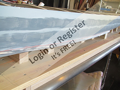
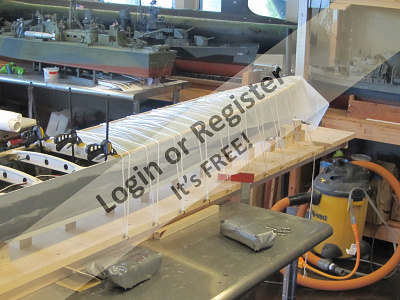
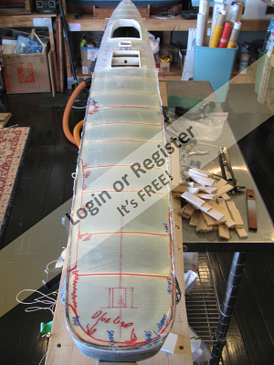
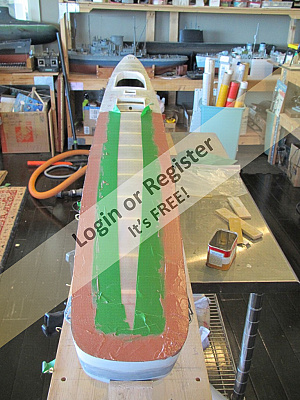
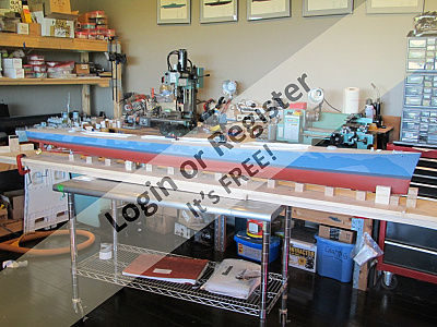
Well, continuing on...I learned this technique from Alan who lives in New Hampshire and builds exquisite models. Far nicer than mine. He taught me to use aluminum tape to simulate hull strakes. It worked pretty well, but not as nicely as his. I used a 3M product that was about .015" in thickness. It should have been thicker, but the thickness is largely made up by the adhesive medium and it can open your model up to dents and dings. I cut strips with a razor knife and applied them to lines I had drawn upon the hull. Once in place where I wanted them, I burnished them down with a stick and sealed the edges with a lacquer primer.
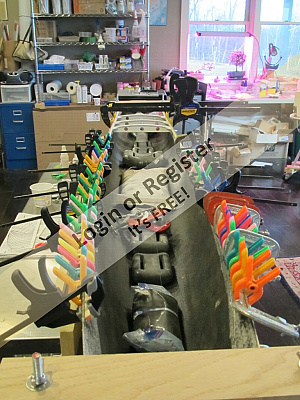
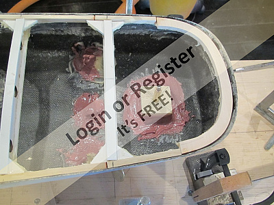
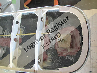
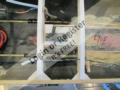
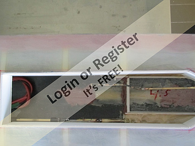
From there I moved to installing the engines, form Component Shop. I wanted an easy way to be able to remove them, if need arose, because there is very little room thru the deck access to unscrew bolts, ect. I chose to use a cleat and cam system. I built the frame, which is epoxied into the hull and the motor mount board then slides into the mount whit one end slipping under the cleat at the stern end. The forward end is then held down with two screen door latches. Goofy sounding but it works well. I know because I have had to since replace a motor that was drawing way too much amperage and it was quite easy to accomplish. I next moved on to installing cleats to hold the two 15 amp hour SLA batteries. They can simply drop into place and be securely held. That done I moved to the very bow deck of the ship. Once the deck is down, my access is really limited so I wanted to get as much done before gluing down the deck a s possible. I glued the first three inches into place to allow me to fit and seal the hawse pipes. I really dislike taking on water thru the hawse pipes to I make an effort to seal them. This can really only be done from inside the hull, so...
My plan for the deck was to use 1/16th inch fiberglass sheet. It will be cut to size and sanded to fit as closely to the hull sides as possible. Thickened West System Epoxy will hold it down. That is for the next installment.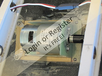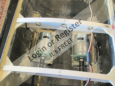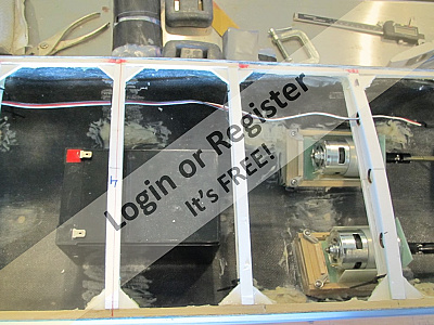
▲
⟩⟩
RNinMunich
Colin H
jbkiwi
stevedownunder
📝 Fletcher
3 years ago by 🇺🇸 ToraDog ( Captain)
Captain)✧ 110 Views · 6 Likes · 3 Comments
Flag
💬 Add Comment
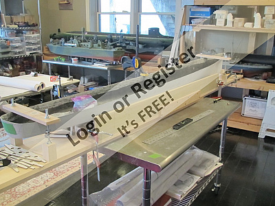
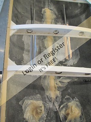
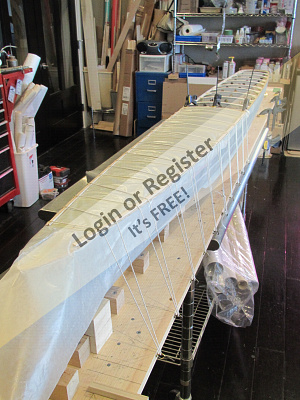
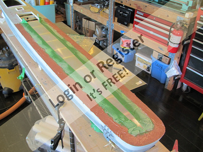
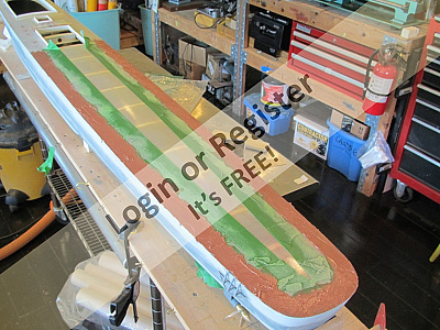
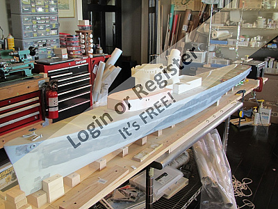
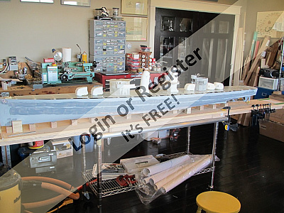
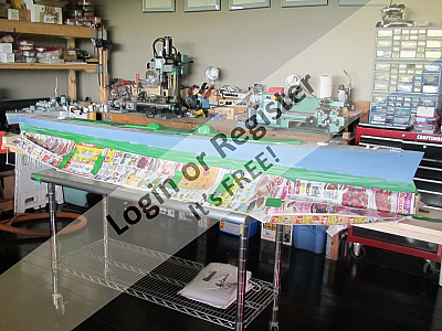
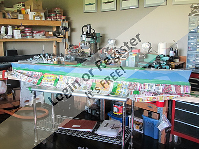
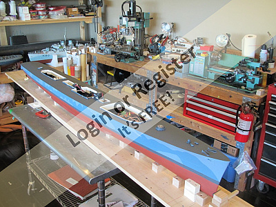
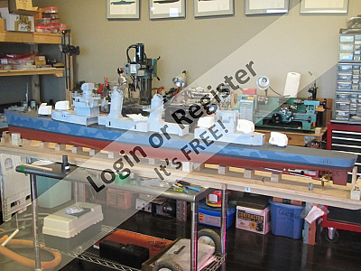
As I mentioned in my last post, the deck material is 1/16th inch fiber glass sheet. I can purchase this thru McMaster Carr here in the States. I think they will ship over seas, but I imagine the cost would skyrocket. Here it is quite reasonable. I test fit the deck and used weights to ensure the camber and shear were accounted for.I glued the deck in place with thickened epoxy and tied the deck down down to account for the shear, which is rather pronounced, and the camber. Wax paper on top of the deck provided a release from oozing epoxy. Unlike plywood sheet, the F/G sheet has not grain and will bend in two directions at once. It is also completely H2O proof and provided a hard surface that take quite a bit of abuse. With the forward half of the deck in place I addressed the rudder servo install, pretty straight forward and plotted out various features such as my smoke generators and house placements. I added remote grease tube hoses for both shaft logs and added a few cleats for added weights near the transom. When all was said and done and I was confident( yeah, right) that I would not need to access the aft have of the hull more than just thru the deck houses, I added the aft half of the deck. This has always caused me great trepidation because it seems that no matter how well I plan thing out, I forget something and the Dremel tool makes an appearance. This time it seems that I got it right(sigh). The stern half of the deck went down as the forward half did. Some sanding to clean up excess epoxy and I was happy, so of. I think the camber is too much, but at least she will shed water. I had marked out the deck house locations and adding a bit of leeway I cut the access holes in the deck and added coamings. Fletchers had a large removable plate on deck over the rudder shaft, I added this and made a removable hatch plate that will allow me to service the rudder if the need arises. My next step was to paint the hull. Pretty standard stuff so I won't go into it.
Next up is deck houses and my impatience......

Next up is deck houses and my impatience......
▲
⟩⟩
Rookysailor
RNinMunich
Ronald
Colin H
jbkiwi
stevedownunder
|
💬 Re: Fletcher
3 years ago by 🇬🇧 mturpin013 (
Admiral)✧ 110 Views · 1 Like
Flag
Thanks Doug I will investigate, I did do some research myself but most companies are only interested in large quantities. How hard can it be to do small quantities I may just have a go
PS this looks a possible ▲
⟩⟩
stevedownunder
|

|
Login To
Remove Ads 💬 Re: Fletcher
3 years ago by 🇩🇪 RNinMunich (
Fleet Admiral)✧ 117 Views · 2 Likes
Flag
Evening Mike,
Try here- ▲
⟩⟩
Rookysailor
stevedownunder
|


|
💬 Re: Fletcher
3 years ago by 🇬🇧 mturpin013 (
Admiral)✧ 114 Views · 2 Likes
Flag
I like the sound of this fibre glass sheet, I've googled it but there doesn't seem to be a UK supplier, I will have to experiment myself.
▲
⟩⟩
stevedownunder
RNinMunich
|
📝 Fletcher
3 years ago by 🇺🇸 ToraDog ( Captain)
Captain)✧ 106 Views · 5 Likes · 3 Comments
Flag
💬 Add Comment
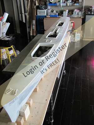
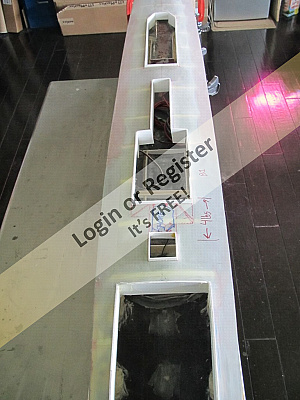
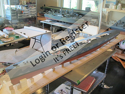
With the deck epoxied down the side gaps were filled with thickened epoxy and sanded smooth. I ran the epoxy inboard a bit to adjust for some of my over generous camber. Putty and Paint make you see what ain't. One of the nice things about working with the thin F/G decking was that I could see through it and the deck beams were visible. Next step was to lay out the placement of the superstructure deck house. There were basically three, but as the pictures show I planned for four access areas that would receive coamings. The deck house were made from the ever present expanded PCV sheet. so I tried to figure the thickness of the sheet, allow for it times 2 and then marked the access opening. The opening were very quickly cut with a Dremel tool and a fiber disc. Eye protection and a respirator were a must. The last thing I needed was F/G inhalation and in my eyes with COVID on top of all of it. Anyhow, the panels cut beautifully and I made the coaming with strips of PVC . Nothing fancy, it extends above the deck about 1/2 inch. If I take more water than that, I'll be in trouble. Can you say Halsey's Typhoon? Fortunately my fuel tanks will always be full.
Moving on the house are just box structures of varying shapes. While making them I did plan for operating features and took those into account where applicable.
I had been spending lots of $ building up my stash of #D printed parts for this hull, so of course once the houses were more or less done I had to see how it looked. Sasa Dobac (diStefan on Shapeways) is a master and was/is a primary source of parts and components. Other than the first house level, the entire bridge structure is his work. Once the house were made to fit I added deck details that would be fixed, ie the fore and aft 5"/38 mount bases and a few details near the bow.
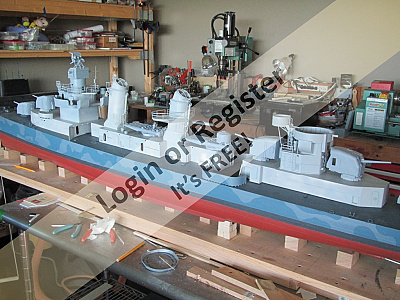
It was now time to paint. The entire hull received multiple coats of a high build filling primer which was sanded between coats. Any divets, dings or ther imperfections were addressed between coats as well. The Fletcher wore Measure 12 Modified camouflage. This consisted all over Deck Blue on all horizontal surfaces, ie, decks and turrets tops. The hull was painted in a unique pattern for each ship, done at the discretion of the painter. Each ship wore a different pattern, even ships built in the same yard. The colors were Sea Blue over Ocean Grey or visa versa. The super structure continued the patterns vertically with colors of Ocean Grey and Haze Grey. Most ships had their patterns sprayed on, but I masked and painted, or free handed. The Bottom was the usual green...got ya, Red with a Weathered Black boot top. Before I forget, I should mention that like many patterns port and starboard were different.

Moving on the house are just box structures of varying shapes. While making them I did plan for operating features and took those into account where applicable.
I had been spending lots of $ building up my stash of #D printed parts for this hull, so of course once the houses were more or less done I had to see how it looked. Sasa Dobac (diStefan on Shapeways) is a master and was/is a primary source of parts and components. Other than the first house level, the entire bridge structure is his work. Once the house were made to fit I added deck details that would be fixed, ie the fore and aft 5"/38 mount bases and a few details near the bow.
It was now time to paint. The entire hull received multiple coats of a high build filling primer which was sanded between coats. Any divets, dings or ther imperfections were addressed between coats as well. The Fletcher wore Measure 12 Modified camouflage. This consisted all over Deck Blue on all horizontal surfaces, ie, decks and turrets tops. The hull was painted in a unique pattern for each ship, done at the discretion of the painter. Each ship wore a different pattern, even ships built in the same yard. The colors were Sea Blue over Ocean Grey or visa versa. The super structure continued the patterns vertically with colors of Ocean Grey and Haze Grey. Most ships had their patterns sprayed on, but I masked and painted, or free handed. The Bottom was the usual green...got ya, Red with a Weathered Black boot top. Before I forget, I should mention that like many patterns port and starboard were different.
▲
⟩⟩
RNinMunich
jbkiwi
stevedownunder
Black Shoe
Colin H
|
💬 Re: Fletcher
3 years ago by 🇦🇺 stevedownunder (
Captain)✧ 105 Views · 0 Likes
Flag
Hi Jonathan,
Looking great, all that 3D printed stuff makes the build progress a lot faster. And with smoke!! Cheers, Stephen. ▲
⟩⟩
No likes yet
This member will receive 1 point for every like received |
|
Login To
Remove Ads 💬 Re: Fletcher
3 years ago by 🇺🇸 ToraDog (
Captain)✧ 106 Views · 1 Like
Flag
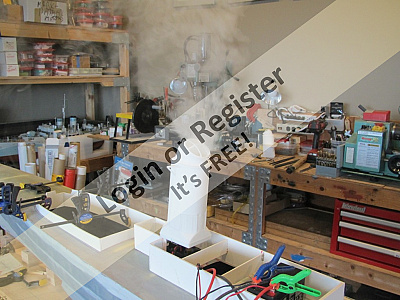
Oh that was nothin'. Both the Halford and the Gear set of the smke alarm systems. The dogs vacated the premises and the alarm company called. All in a days work....
▲
⟩⟩
RNinMunich
|
|
💬 Re: Fletcher
3 years ago by 🇺🇸 Black Shoe (
 Sub-Lieutenant) Sub-Lieutenant)✧ 117 Views · 0 Likes
Flag
I'm betting Mrs Tora Dog was thrilled with that smoke in her house!😀
▲
⟩⟩
No likes yet
This member will receive 1 point for every like received |
📝 Fletcher
3 years ago by 🇺🇸 ToraDog ( Captain)
Captain)✧ 102 Views · 2 Likes
Flag
💬 Add Comment
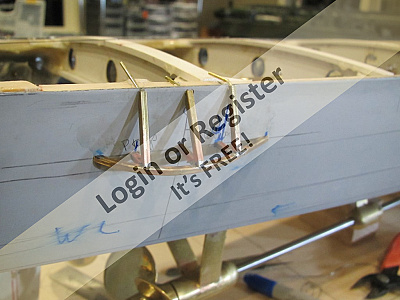
A very brief addition of a couple of points I did not touch on. First is my shaft alignment method. I have become quite partial to the tubing over shaft method. This uses tubing, it can be brass, aluminum, or any other metal. A snug sliding fit works fine. Tubing fitting over the prop shaft and extending forward to fit over the motor shaft is the goal. If there is tension on the alignment tool causing it to bind if slid fore and aft as well as rotated, then there is a significant misalignment. Bearing in mind that it is possible to flex the prop shaft, especially if there is a fair amount of it extending forward from the stuffing box, I align my motor and shaft by shifting and shimming my motor mount until my "tool" slide effortlessly. I then tack the motor mount into place with CA, let it harden, I use a thick slow version, and check my alignment again. If I am happy I then bed the mount into place with thickened epoxy. This seems to be more successful than the MK1 eyeball method.
The other thing I do involves my u-joint between the motor and the shaft. I use double knuckle Delrin joints with metal spiders. I like these for several reasons. 1) They will break if torqued beyond their limits, which is not really that much, but that said it is well within the limits I impose upon the props and shafts. 2) they can be relatively easily adapted to different input and output shaft sizes, 3) they work exceeding well when true alignment can not be achieved. 4) they are readily available. They do have a drawback which is that they can be noisy, especially at low speeds and this is where I found a solution. They are not precision joints and the spiders do have slack which causes chatter. What I have done it to slide some heat shrink tubing over the entire u-joint. I do not shrink it into place. Just the tight sliding fit holds it fine. This appears to keep the cages of the joint in alignment and in doing so the chatter disappeared. Feel free to try it, I do not intend to patent my idea. LOL
That's it. Next post , on with the build.
▲
⟩⟩
Colin H
stevedownunder
📝 Fletcher
3 years ago by 🇺🇸 ToraDog ( Captain)
Captain)✧ 91 Views · 4 Likes · 2 Comments
Flag
💬 Add Comment
It was around this time that I started to really look at electronics and motion requirements. One of he vendors I regularly visit is ServoCity. They do a lot with robotics, especially combat robots. I few years ago they started to carry a line of servos by GoBilda. The line has since expanded and it fit my needs perfectly. GoBilda will also sell direct retail I have since found out. The servos I bought, to animate my turrets and torpedo tubes, rotae 180 degrees, out of the box, and with a servo expander, also available fro GoBilda, they will give 300 degree rotation. An added plus is that they are programable servos that can be made to give 360 degree continuous/reversible rotation with proportional control. I know this sound like an advertisement, but they work. They have expanded their line to include a Torque version of their servo which, while slower is much more powerful. I originally ordered Speed versions of their servos, but have changed them out to the Torque version when I found that some of my turrets dragged and loaded the servos down.
So with my "drives" purchased, I set about making mounts for the servos which drive the five turrets, the MK 37 gun director and the torpedo tubes. It was somewhere around this time that I also discovered the FrSky X9E tray radio. I have talked about these before, but it was a leap for me because I had always used 75mhz analog radios. The learning curve was very steep, even with numerous videos and threads on different forums discussing these units. The is an Englishman who has posted wonderful videos about FrSky and I owe him my understanding.
Going back to my servos and drives for a moment; the hardware for connecting the servos, to the shafts of all the items I wanted to animate, are also available fro the two vendors I have mentioned. Especially nice is a servo adapter that screws into place of the servo arm. It has a clap like shape that tightens around a 1/4" shaft. perfect for my needs and very simple to adjust, not the mention allowing easy removal of the turret, ect.
General planning now entailed smoker placement that would clear the deck houses. On my last destroyer I used one large smoker and piped it to two stacks. It worked very well, but is cumbersome. I also tried to plan out my electronics bay to be neat and accessible, but as usual, neat did not work and accessible is a matter of interpretation. In the end a stacked two level electronics bay fit everything in, so far. I do not have pictures of this part of the build so I'll move on the detailing the houses.
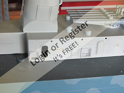
For fittings I used two primary sources, Distefan on Shapeways and Robert Thomas who makes Quartermaster fittings. Robert makes perhaps the finest resin fittings I have come across. I decided to show a number of house doors open and to make functional the house vents.I did this to supply air to the smokers and allow heat from the motors to vent out.
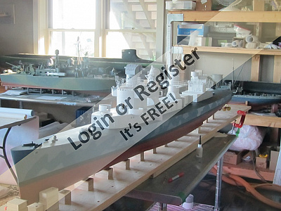
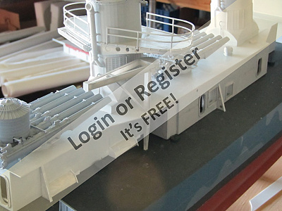
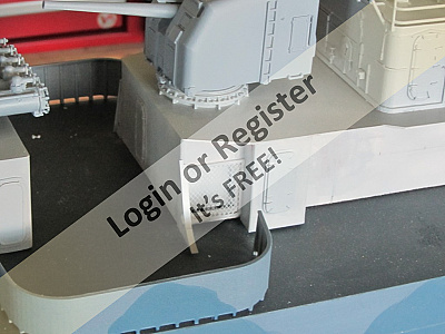
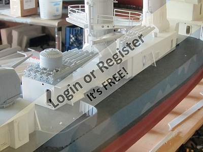
In the first photo, the entire bridge above the 01 level is 3D printed, including the gun director and it's base. Moving aft, the stacks, torpedo tubes, all turrets, the side 20mm shields,and the aft superstructure, again above the 01 level are also all 3D. The time and effort this saves is amazing. All doors are Quartermaster.
I made the house events and started to add hand rails. Many were later removed when I found that I had neglected equipment that interfered with them. Deck access hatches were added, house braces and quarter round house extensions were started. I lined the house portholes with brass tubing and drilled the holes for the future house lights and lined them with brass tubing as well. Valve wheels went in and various reels mounted. The objects alongside the after house are spart K-gun arbors.
Till next time


So with my "drives" purchased, I set about making mounts for the servos which drive the five turrets, the MK 37 gun director and the torpedo tubes. It was somewhere around this time that I also discovered the FrSky X9E tray radio. I have talked about these before, but it was a leap for me because I had always used 75mhz analog radios. The learning curve was very steep, even with numerous videos and threads on different forums discussing these units. The is an Englishman who has posted wonderful videos about FrSky and I owe him my understanding.
Going back to my servos and drives for a moment; the hardware for connecting the servos, to the shafts of all the items I wanted to animate, are also available fro the two vendors I have mentioned. Especially nice is a servo adapter that screws into place of the servo arm. It has a clap like shape that tightens around a 1/4" shaft. perfect for my needs and very simple to adjust, not the mention allowing easy removal of the turret, ect.
General planning now entailed smoker placement that would clear the deck houses. On my last destroyer I used one large smoker and piped it to two stacks. It worked very well, but is cumbersome. I also tried to plan out my electronics bay to be neat and accessible, but as usual, neat did not work and accessible is a matter of interpretation. In the end a stacked two level electronics bay fit everything in, so far. I do not have pictures of this part of the build so I'll move on the detailing the houses.
For fittings I used two primary sources, Distefan on Shapeways and Robert Thomas who makes Quartermaster fittings. Robert makes perhaps the finest resin fittings I have come across. I decided to show a number of house doors open and to make functional the house vents.I did this to supply air to the smokers and allow heat from the motors to vent out.
In the first photo, the entire bridge above the 01 level is 3D printed, including the gun director and it's base. Moving aft, the stacks, torpedo tubes, all turrets, the side 20mm shields,and the aft superstructure, again above the 01 level are also all 3D. The time and effort this saves is amazing. All doors are Quartermaster.
I made the house events and started to add hand rails. Many were later removed when I found that I had neglected equipment that interfered with them. Deck access hatches were added, house braces and quarter round house extensions were started. I lined the house portholes with brass tubing and drilled the holes for the future house lights and lined them with brass tubing as well. Valve wheels went in and various reels mounted. The objects alongside the after house are spart K-gun arbors.
Till next time
▲
⟩⟩
jbkiwi
stevedownunder
Commodore-H
Colin H
|
💬 Re: Fletcher
3 years ago by 🇺🇸 ToraDog (
Captain)✧ 88 Views · 2 Likes
Flag
Steve,
Yes some of the parts were very expensive. Nothing 3D printed is cheap anymore. Shapeways has quadrupled their prices since I started buying thru them, plus they have added a "handling fee" which is a percentage of the order total cost. It happens when a company feels that they have cornered the market and consumers have no choice. Fortunately many of the designers on Shapeways have found other sources to print their designs which make the cost very reasonable. In some cases the finished products were far superior in finish as well, compared to the Shapeways items. I will not name names here, but if you PM me I will share some of my sources. ▲
⟩⟩
Rookysailor
stevedownunder
|
|
💬 Re: Fletcher
3 years ago by 🇦🇺 stevedownunder (
Captain)✧ 84 Views · 0 Likes
Flag
Hi Jonathan,
That's quick progress with the 3D printed stuff, it must be costing a bit? Cheers, Stephen. ▲
⟩⟩
No likes yet
This member will receive 1 point for every like received |


Login To
Remove Ads
Remove Ads