|||
|
|
🗝 Login
🤖 Create Account
Main Menu
🚤 Model Boats
• Forum
• Build Blogs
• Media Gallery
• Boat Clubs & Lakes
• Events
• Boat Harbour
• How-To Articles
• Plans & Docs
• Useful Links
This Website
🔍 Search
📝 Guestbook
👨👩👧👦 Members (7,843)
📖 Quick Site Guide
📣 Support
👥 Membership
Hobby Supplies
🛍️ Online Shop
Not Registered
Go AD FREE & get your membership medal
BRONZE
Less Ads
SILVER
GOLD
Ad Free
Cancel
Anytime
Anytime
£2.50
£4.50
£6.50
Subscribe
Go AD FREE & get your membership medal
BRONZE
Less Ads
SILVER
GOLD
Ad Free
For A Whole Year!
£25
£45
£65
Donate
You Will Be Helping Towards:
Domain Fees
Security Certificates
iOS & Android App Fees
Website Hosting
Fast Servers
Data Backups
Upkeep & Maintenance
Administration Costs
Without your support the website wouldn't be what it is today.
Please consider donating towards these fees to help keep us afloat.
Read more
All donations are securely managed through PayPal.
Many thanks for your kind support
Without your support the website wouldn't be what it is today.
Please consider donating towards these fees to help keep us afloat.
Read more
All donations are securely managed through PayPal.
Many thanks for your kind support
Join Us On Social Media!

|

|

|
Download The App!
Login To
Remove Ads
Remove Ads
Login To
Remove Ads
Remove Ads
🏝️ About This Website
☝️ Terms of Service
🔏 Privacy Policy
Model Boats Website
Model Boats Website
Home
Forum
Build Blogs
Media Gallery
Boat Clubs & Lakes
Events
Boat Harbour
How-To Articles
Plans & Docs
Useful Links
Welcome to the Model Boats Website! A place for all model boaters!
Feel free to browse through the website, ask your questions, upload your photos or even start your own blog!
Feel free to browse through the website, ask your questions, upload your photos or even start your own blog!
Login To
Remove Ads
Remove Ads
Today's Question
What is the term for the curved shape of a boat's hull?
ANSWER >>
>
Today's Wordle
6 LETTERS
>
Trending Now
Forum
Question of the Day?
Sheer?
No comment.
Michel-C.
🇨🇭 Mike Stoney

11 minutes ago
Forum
LCM3 landing a Sherman M4A3(105) howitzer
Google, was on some LCM5s back in the 70's. (The LCM5 was larger and able to load a military semi with a trailer.) Had some interesting things happen on board including a guy breaking his arm when the boat hit the shore while going fast. They stop pretty quickly with that wide bow.
Lew
Florida ️, USA
🇺🇸 LewZ

12 minutes ago
Forum
I miss Graupner!!! And Robbe too.
Hi all,
Unfortunately, the demise of model shops is unstoppable.
Here in Switzerland, you can only count these good model shops on one hand . .
Apart from the Internet.
The new technologies are in the hands of our successor hobbyists and young people. Tiktok and everything else is now their world. What a pity . . .
So what???
Michel-C.
🇨🇭 Mike Stoney
30 minutes ago
Forum
Wordle of the Day?
Needed the clue in 4, must remember to eat more bananas
🇬🇧 Doogle

1 hour ago
Forum
Cheddar Electronic gas control valve instructions
Hi Denes
If you would be so kind, I would appreciated it.
Thank You
Mike W
🇬🇧 Steam-mad

2 hours ago
Forum
Useful Battery ???
Colin, your are going through some pretty rough times. I hope all will turn around and time will help heal some of the pain and recovery. Prayers to you and you family. Most sincerely, Lew
🇺🇸 LewZ
8 hours ago
Harbour
Re: Lulonga River Tug
Yes you are correct, well spotted. The drive cog is slightly larger than the one on the shaft. This is due to the space allowed. The speed is controlled by an electronic speed controller . The geared motor draws little current so on 12 volt will run for hours on a 3 amphour battery. To much throttle just whisks the water. The paddle wheels are quite wide with a lot of paddle in the water providing power. The mist steam unit output is linked to the throttle as is the sound generator.
🇬🇧 wmbc40

10 hours ago
Harbour
Re: 3. Old Commodore / Graupner
Let's wait for April 28th.
Nice things to put the names of family members.
🇮🇹 AlessandroSPQR
12 hours ago
Harbour
Re: 4. Fishing boat "Aline"
Hi all,
On 28 April this year we have our baptisms at the club.
"Aline" will be baptised on this Sunday. We are hoping for great weather.
Keep your fingers crossed!
By the way, my granddaughter Aline is the godmother. I named this boat after her, this is her favourite boat.
Greetings Michel-C.
🇨🇭 Mike Stoney
13 hours ago
Forum
International Associations
Hi Model Boaters
Please help me out. I am looking for an International Association / Federation that represents RC Boating. I have all the Model Power Boat / Radio Sailing Associations and Naviga. I'm looking for something similar to the latter but with an actual contact person / number to contact for collaboration in Africa.
🇿🇦 Rudy-M

16 hours ago
Harbour
Re: 5. Old Stern wheel steamer
The Wheel of time.
That’s a nice name
Isaac
🇺🇸 Isaac
16 hours ago
Forum
Modello RC scala 1/60, di piroscafo armato a goletta, liberamente ispirato alle cannoniere classe US
Glad to see that Colin is posting again.
🇺🇸 Len1

17 hours ago
Forum
Blast from my past
River Rat! With a wonderful engine detail! Simply...
🇺🇸 jumpugly

19 hours ago
Blog
Re: April 13 2024
Really enjoyed seeing your photos. Keep up the good work !
🇬🇧 flaxbybuck
19 hours ago
Blog
Re: Scratchbuilt Esso Deutschland 1:150
You've got some pretty sturdy frames in there Jock. I enjoyed looking at your progress photos. Good luck with the rest of the build very impressive so far.
🇬🇧 flaxbybuck
20 hours ago
Blog
Re: MLB Begin
Good luck with your project Kevin. Enjoy the build. That's what it's all about !
🇬🇧 flaxbybuck
20 hours ago
|

New Promotion
Leading Seaman
wmbc4012 hours ago
New Member
United Kingdom
 TommyT1
14 hours ago
New Member
United Kingdom
KenC117 hours ago
New Member
United Kingdom
KenV20 hours ago
New Member
Australia
Pdjones21 hours ago
New Member
United Kingdom
malcolmr11 day ago
New Member
Australia
PhillipH2 days ago
New Member
United Kingdom
JaneA2 days ago
New Member
Turkey
MehmetAliB2 days ago
New Member
Australia
GeoffA12 days ago
Birthday This Week
Turns 70
RossM2 days ago
Birthday This Week
Turns 46
 Schmango
2 days ago
New Member
United States
CJ2 days ago
New Member
Slovakia
RomanS3 days ago
New Member
United Kingdom
TonyF13 days ago
New Member
United States
Colin B Waitt3 days ago
New Member
United States
fbcmhall3 days ago
Birthday This Week
Turns 77
 Lauriem
3 days ago
New Member
United Kingdom
JollyRoger3 days ago
New Member
United Kingdom
PhilipP3 days ago
New Member
United Kingdom
michaeld13 days ago
New Member
Switzerland
maran494 days ago
New Member
United Kingdom
jacks4 days ago
New Member
United Kingdom
georgeC26 days ago
New Member
United Kingdom
JohnJ17 days ago
New Member
United Kingdom
Geoffreym17 days ago
New Member
Spain
JosLuisB7 days ago
New Promotion
Midshipman
 EdW
EdW7 days ago
New Member
Argentina
MatiasO8 days ago
New Member
United Kingdom
BridgetH8 days ago
New Member
United Kingdom
Jim18 days ago
New Member
United States
DanO8 days ago
New Promotion
Able Seaman
Steves-s8 days ago
New Promotion
Captain
Brightwork8 days ago
Birthday This Week
Turns 67
Stephen T9 days ago
Birthday This Week
Turns 79
Robert 879 days ago
New Member
United Kingdom
DougW10 days ago
New Member
Germany
UlfF10 days ago
New Promotion
Leading Seaman
impartit10 days ago
New Member
Norway
ToreL10 days ago
New Member
United Kingdom
GregG110 days ago
New Member
Turkey
hakank10 days ago
New Member
Brazil
OlimpioA11 days ago
New Promotion
Leading Seaman
whittonm11 days ago
New Member
Australia
JimP11 days ago
New Promotion
Captain
flaxbybuck12 days ago
New Member
Hong Kong
tufub12 days ago
New Promotion
Commodore
AlessandroSPQR12 days ago
See More
Forum Topics
Question of the Day?
Sheer?
No comment.
Michel-C.
11 minutes ago by 🇨🇭 Mike Stoney ( Commander)
Commander)
Website Related
2375 Posts
6078 Likes
6078 Likes
Started
1 year ago
by fireboat
1 year ago
by fireboat
Latest
11 minutes ago
by Mike Stoney
11 minutes ago
by Mike Stoney
LCM3 landing a Sherman M4A3(105) howitzer
Google, was on some LCM5s back in the 70's. (The LCM5 was larger and able to load a military semi with a trailer.) Had some interesting things happen on board including a guy breaking his arm when the boat hit the shore while going fast. They stop pretty quickly with that wide bow.
Lew
Florida ⛱️, USA 🇺🇸
12 minutes ago by 🇺🇸 LewZ ( Captain)
Captain)
Website Related
6 Posts
5 Likes
5 Likes
Started
8 hours ago
by LewZ
8 hours ago
by LewZ
Latest
12 minutes ago
by LewZ
12 minutes ago
by LewZ
I miss Graupner!!! And Robbe too.
Michel mon ami, Michael my friend how can such à Young lad Tell so much wisdom?!?!
Your wife Must have had à terrible job to educate you. Otherwise it is impossible 😂😂😂😂
I have à modelshop( for Not saying a Model Supermarkt 10 minutes Walk from my home and i ALWAYS but things there as i don‘t want that hé disappears.
Name of the Shop modelbouw Baillien
21 seconds ago by 🇧🇪 hermank ( Captain)
Captain)
Hobby Chit Chat
4 Posts
12 Likes
12 Likes
Started
5 hours ago
by Cashrc
5 hours ago
by Cashrc
Latest
21 seconds ago
by hermank
21 seconds ago
by hermank
Wordle of the Day?
Needed the clue in 4, must remember to eat more bananas 🍌 😋
1 hour ago by 🇬🇧 Doogle ( Commodore)
Commodore)
Website Related
1286 Posts
2640 Likes
2640 Likes
Started
10 months ago
by fireboat
10 months ago
by fireboat
Latest
1 hour ago
by Doogle
1 hour ago
by Doogle
Cheddar Electronic gas control valve instructions
Hi Denes
If you would be so kind, I would appreciated it.
Thank You
Mike W
2 hours ago by 🇬🇧 Steam-mad ( Able Seaman)
Able Seaman)
General Resources
3 Posts
1 Like
1 Like
Started
13 hours ago
by Steam-mad
13 hours ago
by Steam-mad
Latest
2 hours ago
by Steam-mad
2 hours ago
by Steam-mad
|
|
Login To
Remove Ads
Remove Ads
Build Blogs
2 Posts
3 Followers
14 Likes
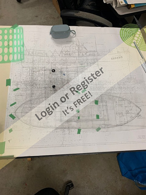
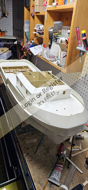
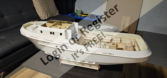
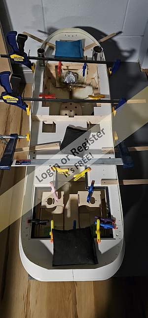
52' Motor Lifeboat Victory
One of my nine-year projects is coming to an end. I am sad to see it completed in some ways, overjoyed in others. Many projects have been begun and shelved over those nine years; some are in the trash now.
What is known is the 213' WMEC-168 Yocona is hit or miss whether my attempts to waterproof a static hull will be successful. So on hold or a side project.
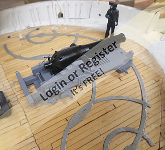
The Gunboat Philadelphia is on-going at work between shifts.
PBY that doesn't Fly I will place on hold, pending possible actual flight. (That will put three aircraft inline to be completed.)
The battleship North Carolina....Big. Not so complex as physically large undertaking.
SO, begin at the beginning as I tell my students. I pondered purchasing the laser-cut kit from Canada, but it is just frames, deck, and pilothouse. Yes, it is 1" to one foot scale, and would match my 44' MLB perfectly, but $286 plus shipping? For me too much, I will build at 1/24th scale for now. Small enough to store, big enough to detail and outfit with running gear.
My 44 MLB, is a leaky, but I am installing an automatic bilge pump. I get so much joy out of running it, and I will have the tri-fecta of MLB's 36', 44', and 52'. The 213 should be complete around the time I finish, so four CG projects in a years time, plus the Philly is a quick build. So, it is a year, year and a half plan.
This will be a slow one.
Non Boat picture is project that is almost complete.
Kevin
🇺🇸 KevinH

2 days ago


2 Posts
7 Followers
26 Likes
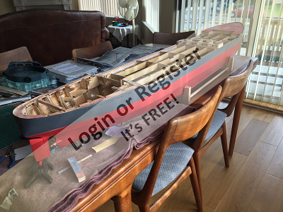
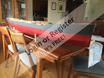
Scratchbuilt Esso Deutschland 1:150
When I first posted a thread under ... a dreamproject.. I didn't realize it was the wrong forum category. So here is my built blog. I will spare you the original introduction as I have made progress which and most of you are already familiar with my project.
The hull was built merging 2 methods on a simple keel plate from plywood, bow and stern structure bread and butter and hull in between 3mm planks on frame.
The entire main deck is intended to be removable with a drainage irrigation system of plastic corner moulding (from a building supplier) along top of hull and flush at poop and back deck structure. The deck is made of 1/4" plywood skeletal structure incorporating midship deckhouse. Hull glassed with lightest cloth available after 2 coats 2-epoxy sealer and paint primer followed by final coat except top (above waterline) grey will be applied once I have finished doing any necessary adjustments. There have been a lot of them since I realized many inaccuracies in dims etc. I wasn't happy with.
Here are photos in the progress (some may have already been posted in the original post.
More a bit later next week.
🇨🇦 JockScott

3 days ago


53 Posts
16 Followers
258 Likes
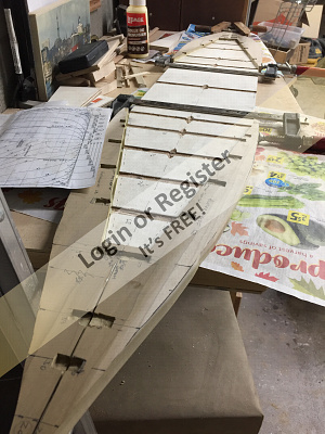
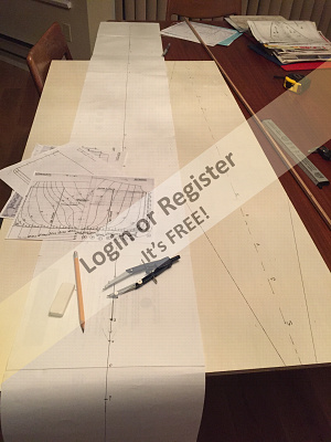
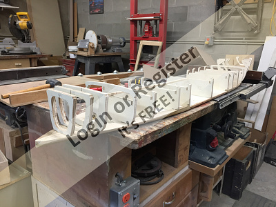
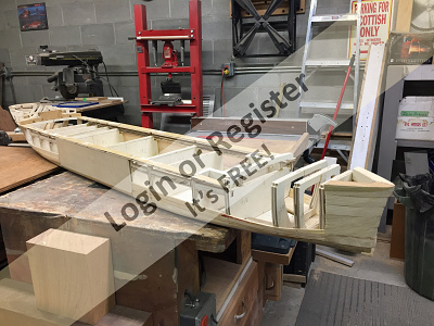
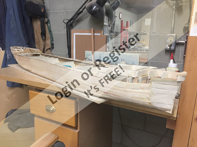
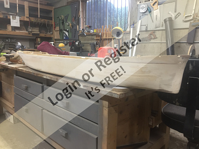
BLUENOSE
Started 2020 with plans by P F Eisnor from Nova Scotia
34 pairs of ribs
🇨🇦 RossM
3 days ago


4 Posts
11 Followers
39 Likes
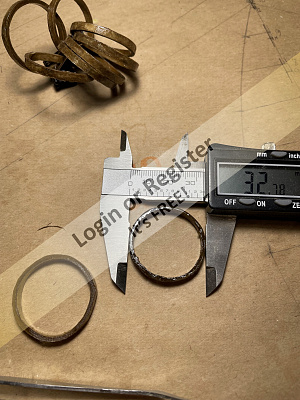
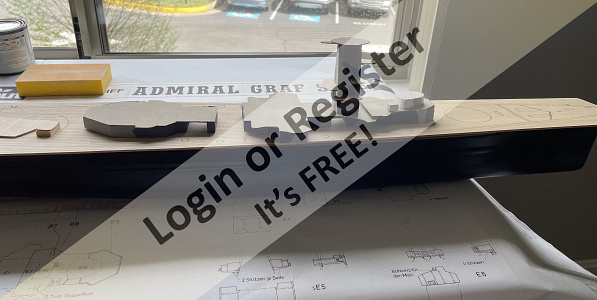
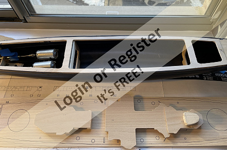
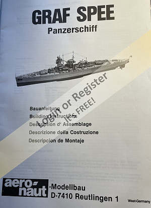
Aeronaut Graf Spee
I bought this kit about 10 years ago from a German model shop. It is definitely old-school, with great detailed plans, detailed stock list, but no instructions beyond a couple of paragraphs. I have not built a model in 20 years but was very active in my youth 50 years ago. I find that my skills have deteriorated and this will not be a great build, but it is enjoyable solving the problems and figuring out how to build this thing.
It has a plastic hull, a very nice plastic fitting set, but the rest of the kit is wood, with many pieces which have to be cut from printed sheets. Luckily, I have access to a wood shop with jigsaw and sanders.
I have fitted out the hull, added the motors, and started the superstructure. Stay tuned for further progress, I hope.
🇨🇦 whittonm
3 days ago

25 Posts
19 Followers
185 Likes
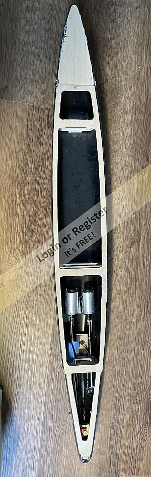
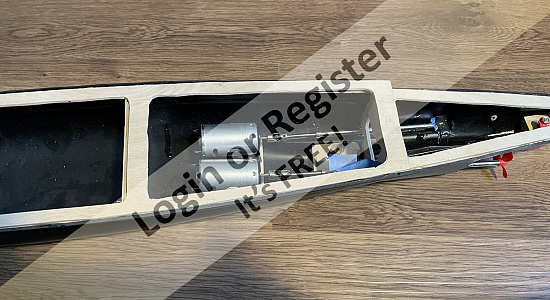
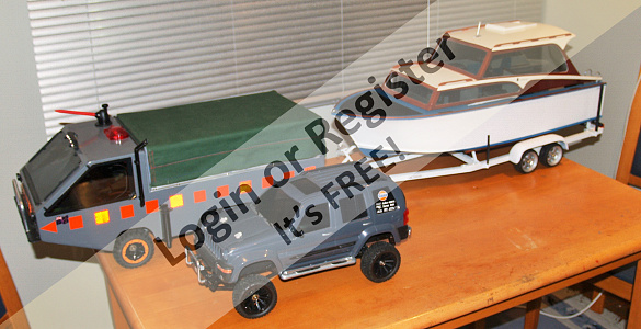
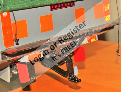
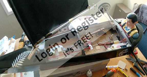
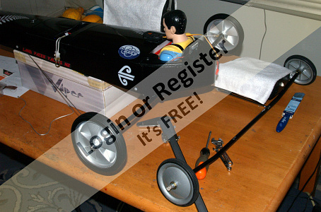
THE AMPHITRUCK
Decided to do something other than a boat this time, but still with a nautical purpose,- a 6 wheel twin diff twin prop swimming truck. Been done before, but I thought I'd have a go at one of my own design. Drew up some side and end templates and made a start, Purchased all the mechanical bits, (diffs, front axle, prop shafts, props, ESC, wheels,) over a few months from uncle ALI and added them to stuff I had in my collection.
Using cheap 3mm packing ply, I made the floor base ( to suit the diff and front axle widths) and strengthened it with 10x10 ally angle. Next,-cut out the sides and front and back panels. The floor was scored at the front and back to allow it to be bent up to the sides for gluing. Holes were cut in the floor to allow the diff heads to protrude through.
I had to modify the front axle to suit the width of the diffs by adding in an ally angle center section. Also had a play with setting the diffs and drive-shafts up with universals. Drive motor is a 380 1500 RPM @ 12v geared reduction drive, which is the one I first used in my Jeep tow wagon for my Hartley, (replaced it with a 1000 RPM version for more torque) and uses a 3s LiPo and Quicrun 40A ESC.
🇳🇿 jbkiwi

4 days ago


3 Posts
8 Followers
45 Likes
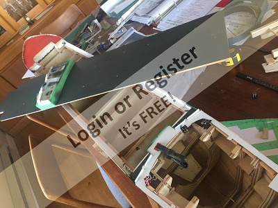
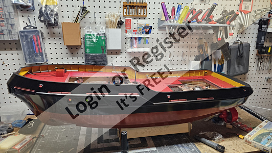
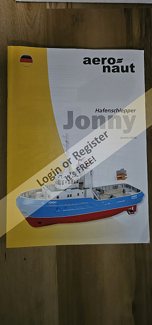
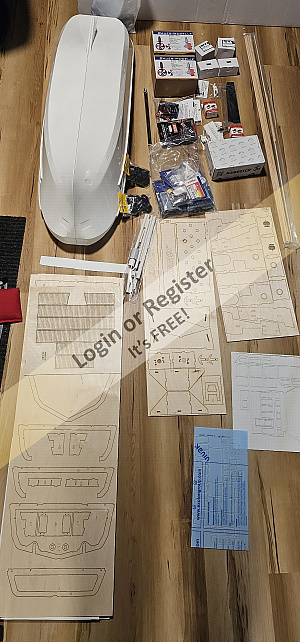
Aeronaut Jonny
Hi all, I started a new build during Christmas and I'm just about ready to start painting the haul so I figured its a good time to get the build log going.
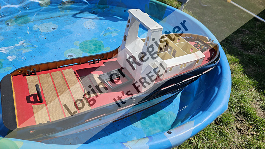
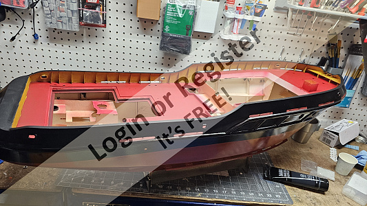
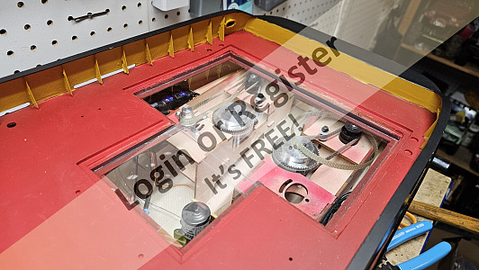
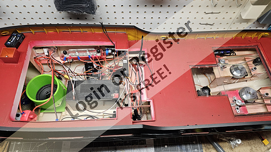
I've had this kit for about a year now, purchased from Bauer in Germany along with with the recommended equipment including their Schottel Drive system. The plan is to have the two Schottel drives, a bow thruster, one working Anchor (possibly two in the future of off the same winch), a sound system, two working radars, working spot light with pivot in pitch and yaw, always on nav lights and interior lights, RC working main winch and manually operated bow and side winches, tow separate working fire monitors able to rotate individually, possibly a smoke generator and final an auto bilge system This comes to a total of 18 RC, unfortunately I only have 16 available so we will have to see what ends up in the ship.
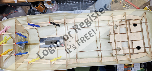
So far I have the drives and bow thruster all fit and ready for assembly. I then built up the frame work and made the holes for the fire pumps and bilge. then had to build the lower deck house so I could fit the deck in the right place on the ship. Once the deck was dry fit I cut the scuppers then glued the deck down. I then set to work making the deck splash proof by installing and extending the kits coaming. I also add a drop floor under the aft hatch that I'm hoping will allow me to keep the water that gets on the deck from leaking down into the haul. Now I've got the Bulwark stanchions and handrails just about complete. I also started work on some of the deck items as I need the locations to work out some of the modifications I'm working through.
I hope to start painting the haul soon, I'm going to try brush painting this ship as I was able to find some nice paints at an Art supply store and I don't have much access to a place to spray paint in the winter. I do think I will spray on the primer first and hope it helps absorbed some of the brush marks.
🇨🇦 Westwind
4 days ago


56 Posts
16 Followers
344 Likes
Constellation
Made the framed glass portion of the skylight. They're hinged so I can get a finger inside to flip the power switch on or off.
They're made from clear plastic from some packaging, basswood, and brass wire.
🇺🇸 Jerry Todd
8 days ago


9 Posts
19 Followers
120 Likes
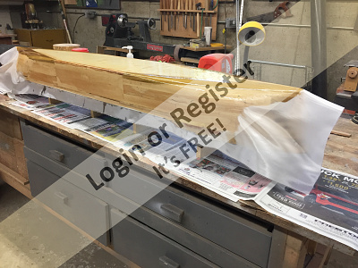
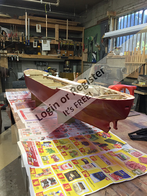
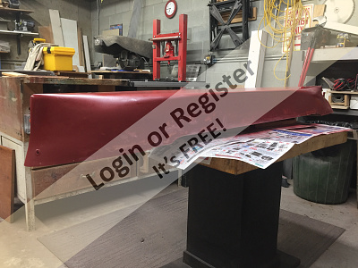
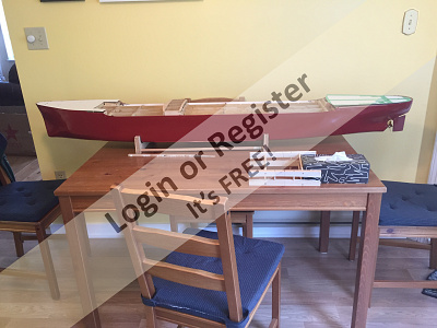
1949 40' Chris Craft Challenger
Hello all.... I have started a new project!! progress so far... she will be 32 " LOA and twin screw.
🇨🇦 Brightwork
8 days ago


29 Posts
19 Followers
370 Likes
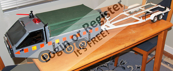
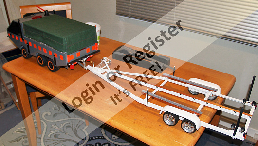
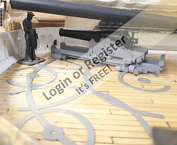
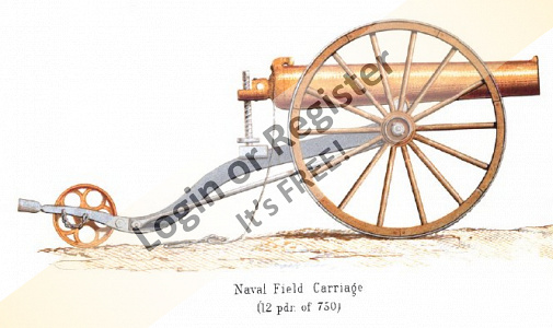
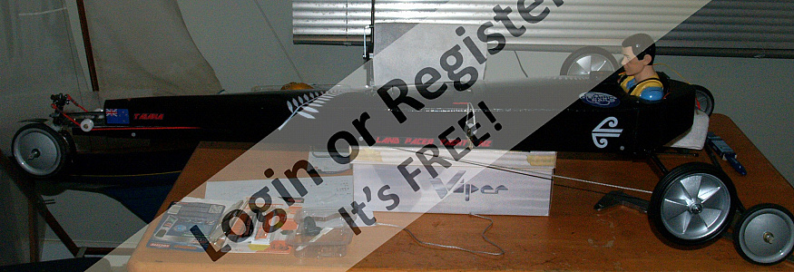
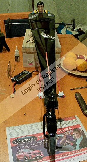
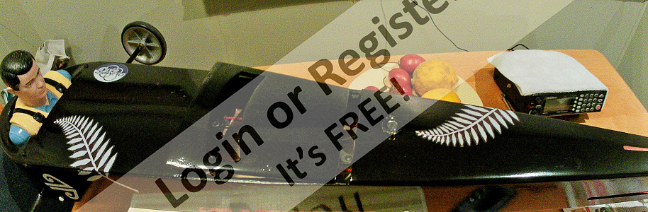
Ship of the desert ? new project
Started the latest project. Spotted these nice 105mm rubber tyred wheels in the big hardware store, and thought they deserved having something to be attached to,- hence the new project.
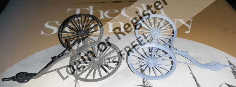
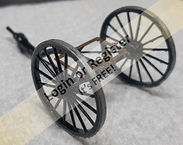
Scratch building using my 'cut it and see' method Started with a 20x20mm ally angle frame (main V from one piece angle cut and bent with bent and bolted rear cross bar) Rear axle is 10x1mm ally tube, with stub axles (from 10mm bright steel) turned down to fit inside and turned down for a 6mm securing Nyloc nut, and a rear shoulder for the wheels.
Stub axles and tube are drilled through 3mm and secured with 3mm machine screws.
Front axle is 6mm rod from an old sponge mop, and is bent and angled for a bit of reverse castor. 50x3mm ally strip added to the front of the frame for reinforcing and to mount 'stuff' to. The front steering head bush is 10mm bright steel drilled 6mm to be attached to?
Tune in next time for another thrilling instalment
JB
🇳🇿 jbkiwi
8 days ago


1 Post
5 Followers
3 Likes
To switch or not to switch ?
I wrongly entered my last post in the 'how to' section where, it seems, you are unable to respond. So here is my query for which I am seeking your guidance.
I have a motor circuit that comprises : 5S 5000mAh 30C Lipo; 40A fuse; 90A marine ESC; 3 x 20A fuses; 46 x 50 870KV brushless motor. There are no switches in the circuit yet.
1.Should I have a switch serving the battery ?
2. If yes, what rating ?
3. Should I have a switch between the ESC and the receiver ?
Any advice or guidance gratefully received.
🇬🇧 flaxbybuck
9 days ago

37 Posts
21 Followers
249 Likes
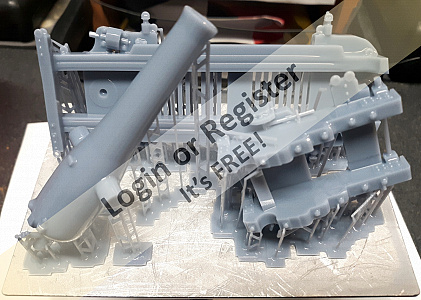
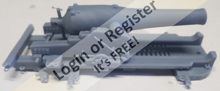
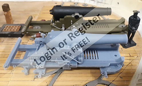
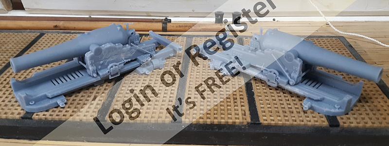
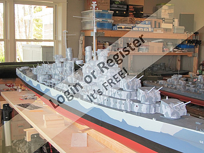
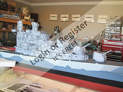
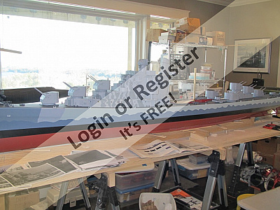
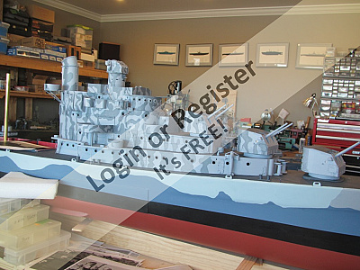
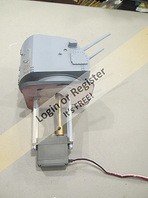
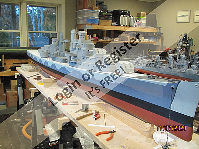
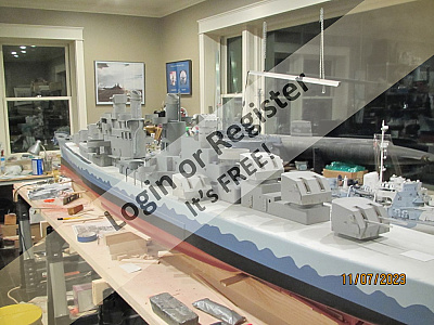
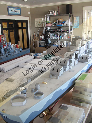
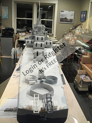
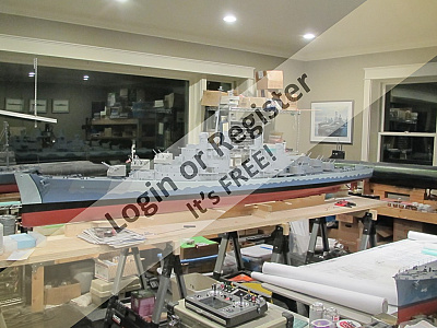
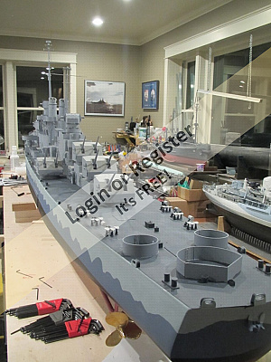
A new build
I will, most likely, have to rename this Blog, at some point.
In the mean time...please do not expect much for a while as she is in her very early stages.
First a disclosure: This hull was built for me by another gentleman. It was delivered in a not quite completed state. Therefore I have spent the last two month working on it to get to it's present state.
So.. what is it? She is one of four ships in a class that was later enlarged to around eight maybe ten members of the class. Her main armament was eight 5"/38 caliber twin turrets. She and her class namesake sister were both lost during the Naval Battle of Guadalcanal. This ship is most noted due to the loss of an entire generation of one family, five brothers.
This should be enough for identification.
She is being built in my preferred scale, 1/48th or 1/4"=1'.
This ship was used for numerous camouflage scheme experiments and, sadly, there is little definitive documentation to pinpoint her second to last and last schemes carried. That said, my plan, subject to change without notice or reason, is to present her as she appeared following her New York Navy Yard overhaul, or perhaps as she may have appeared after repainting in Placentia Bay NewFoundland, 1942.
She measures out to 11' 3" and her power plant is to be two 24 volt Buehler motors.
Pictures of her and the build to follow.
Wish me luck please, she will not fit in my van....
🇺🇸 ToraDog
9 days ago


1 Post
6 Followers
11 Likes
Kathryn - a Thames Bawley - 10
About the mainsail, topsail and large staysail.
The gaff is lifted by the uphaul (Pic 1) with the halyard being tied off on a mast cleat (Pic 2) Note this is not how the real thing would be done, but is my method that works on a model.
There are a number of cleats attached to the foot of the mast. These are glued and attached using long screw eyes ( see earlier blog)
Pic 3 shows the gaff 'spreader' (my term) the halyard passing through various pulleys before travelling down the mast to a cleat (Pic4) More about pulleys in the next Blog.
The following photos show the principle sails and how they are attached. I have made a number of other sails not shown here, including a smaller main sail and topsail, a smaller staysail, a jib and a flying jib. These can be set to suit different wind strengths.
The mainsail (pic 5 ) is an old cotton sheet stained with tea. I have sewn reinforcement patches into the places that will come under stress or tension, and bias binding onto all edges. Metal eyes or hooks are then sewn into the clew (Pic 6), the tack (Pic 7), the throat (Pics 8 and 9), and the peak (Pic 10 ). Pic 11 just shows how the bias binding is used to finish the sail edges.
Attachment points are shown in the next few pictures. Pic 12 the tack eye, Pic 13 the throat eye, Pic 14 the peak uphaul and Pic 15 the clew outhaul. Pic 16 shows the main sheet emerging onto the deck, passing through an eye on the travel horse and heading for the main boom.
The topsail is shown in Pic 17, already stained with Colron dye, corners reinforced and bias binding sewn on. The following five pictures show the topsail foot, clew and peak in detail.
Pic 23 is the large staysail, with the tack, clew and head shown in the final pictures.
None of the methods used for attaching these sails is authentic. My aim is to be able to sail the boat and enjoy seeing it on the water. I therefore need to be able to attach or detach the sails quickly at the pondside. I use a variety of attachments, principally eyes and hooks. I try to make these as neat as possible, and not detract from the appearance.
We often talk about 'passing the ten foot test', meaning if it looks OK when ten feet away, then it is OK. However, viewing these photos I can see just how poorly I have finished off sewing in the sail corners. There are too many ragged edges and untidy hand sewing. In future I must remind myself of this and do better. (Sounds like my school reports - 'must do better !')
🇬🇧 flaxbybuck
12 days ago


|
|

Media Gallery
INGA IV
4 days ago by philcaretaker
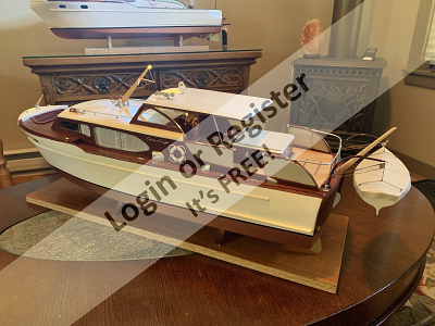
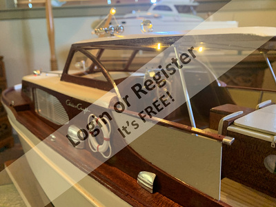
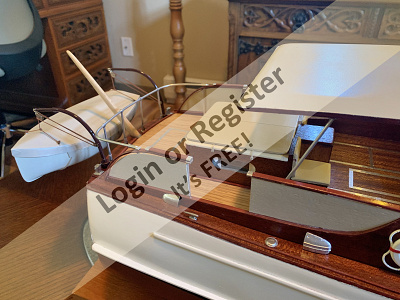
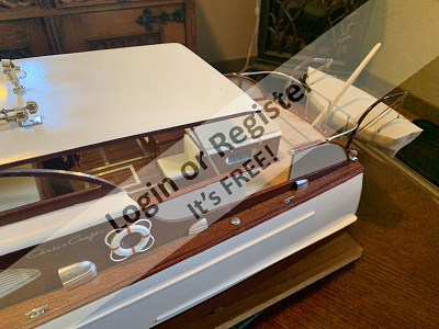
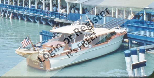
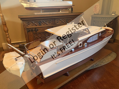
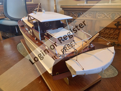
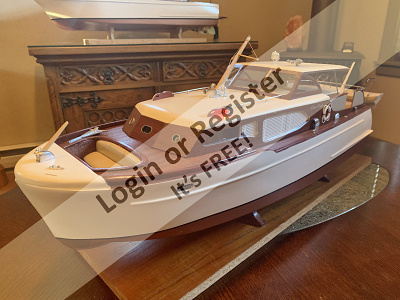
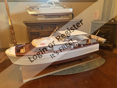
Lake Union Dreamboat
6 days ago by Brightwork
1958/9 50/55' Chris Craft Constellation
8 days ago by Brightwork
Filming "Dinghy Dan"
19 days ago by philcaretaker
"Dinghy Dan"
19 days ago by philcaretaker
"Dan, Dan the Dinghy Man"
22 days ago by philcaretaker
"Dinghy Dan"
23 days ago by philcaretaker
RNLI Severn Class
23 days ago by Rudy-M
Onboard a Focus 2 RC yacht
23 days ago by Rudy-M
Andy sails Topaz with df65's
24 days ago by MartinH2
RC Shark vs Orca?
25 days ago by Rudy-M
Topaz 60" J class yacht
28 days ago by MartinH2
|
|

Login To
Remove Ads
Remove Ads
Boat Clubs & Lakes
Recent Updates In Places

|
Model Boating Association of South Africa
12 days ago by 🇿🇦 Rudy-M (
Warrant Officer) |
|
|
BUXTON MODEL BOAT CLUB
22 days ago by 🇬🇧 philcaretaker (
Commodore) |
|
|
Rawdon Model Boat Club
23 days ago by 🇬🇧 MikeC3 (
Petty Officer 2nd Class) |
|
|
Sonstraal Dam
1 month ago by 🇿🇦 Rudy-M (
Warrant Officer) |
|
|
Cape Town Scale Model Boat Club
1 month ago by 🇧🇪 hermank (
Captain) |
|
|

Upcoming Events

|
May
5 2024
|
1 Day Only!
|
Edina Model Yacht Club - Spring Breakfast
Starts 12 days time
|
|
|
Jun
8 2024
|
1 Day Only!
|
RAWDON MBC OPEN DAY
Starts 2 months time
|
|
|
Jun
9 2024
|
1 Day Only!
|
Edina Model Yacht Club - Parade of Boats at Centennial Lakes Ponds
Starts 2 months time
|
|
|
Aug
11 2024
|
1 Day Only!
|
Edina Model Yacht Club - Lighthouse Night #1
Starts 4 months time
|
|
|
Sep
7 2024
|
1 Day Only!
|
Edina Model Yacht Club - Lighthouse Night #2
Starts 5 months time
|
|
|
Boat Harbour
4 Photos
16 Likes
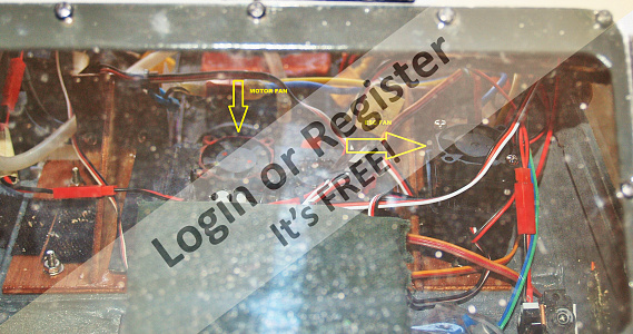
Lulonga River Tug
Lulonga steam river tug. Broad beam twin stern paddles. Very stable and graceful on the water. Single motor (12 volt)chain driven from geared motor. Fitted with smoke mister, lights and sound. Unusual model built from plan. Lovely to sail on a summer evening.
🇬🇧 wmbc40
17 hours ago
0 Attributes
11 Comments
7 Photos
9 Likes
Oppie
Way back when, there used to be a company producing grp hulls, they were based in Holyhead(?) or nearby, the business was sold, and I discovered they had some pieces for the Oppie, I bought them, constructed the model, sailed it, was impressed, so much so I embarked on the construction of the other exact 1:4 scale models.
🇫🇷 stotty1111
5 days ago
0 Attributes
3 Comments
3 Photos
17 Likes
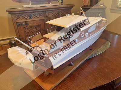
Graupner Commodore
I acquired this Commodore and made some modifications so she is now a Chris Craft Roamer 37'
🇨🇦 Brightwork
8 days ago
4 Attributes
11 Comments
2 Photos
18 Likes
Billings Smit Nederalnd
I aquired this for free and did some restoration on her. I will probably give her to my brother.
🇨🇦 Brightwork
8 days ago
4 Attributes
9 Comments
5 Photos
12 Likes
1949 40' Chris Craft Challenger
This is based on the Dumas model plans. Model was produced by dumas as a kit in the 50's. I semi scratch built her from the plans.
🇨🇦 Brightwork
8 days ago
8 Attributes
5 Comments
9 Photos
11 Likes
Steam Power
Not strictly marine based, but the Stuart D10 is destined for a 1:12 Customs Launch, Active, built by Cox & Co Falmouth 1912, and stationed at Gravesend until the '30's.
Kit of castings, machined and built by myself along with the horizontal engine.
The others have been bought at knock down prices over the years!
They all need sprucing up!
The boiler was bought several years ago from an Australian outfit, at the time it seemed incredibly cheap, but was probably caused by the exchange rates between the Australian dollar and the pound!
It came complete with lagging, planking and other bits and pieces, cannot be exact as I cannot find the box with the pieces in, cannot remember if it was complete with burner!
I now have the thermal blocks (ex night storage heater) to construct a hearth to continue with the installation etc.
Photos of 'Active' to follow it is stored at the club house!
🇫🇷 stotty1111
15 days ago
0 Attributes
2 Comments
9 Photos
22 Likes
Oystercatcher
Here we have Oystercatcher, another product of the noughties.
The full size boat is designed for inland waters, weekend cruising, it can be used as a floating tent using the spars and sails.
Designed by Conrad Natzio of East Anglia, it is designed for garage construction, using 6 sheets of marine ply or even water resistant ply.
I met Conrad at an exhibition at Alexandra Palace, had a chat with him was given plans of several of his designs, chose to build Oystercatcher, kept in touch and was invited to a weekend expo at Beale Park, adjacent to the Thames, he used my model on his stand, a very nice man!
The model is an exact scale of 1:4, I enjoyed the build, but the control was not an easy installation, the boat being so open.
Went on to sail her at an exhibition held in Swansea at the Maritime Museum, they had a pond there so was able to try sailing, it worked well, but I felt I needed to add a keel to bring a little more stability, but house moves etc got in the way.
Makes a nice static model!
I will endeavour to get more photos when the wind is calmer!
🇫🇷 stotty1111
18 days ago
0 Attributes
6 Comments
2 Photos
11 Likes
Mini Submarine
Another toy, courtesy of Amazon 7 or 8 years ago.
I bought the beast for about £12 / 15€. It was on offer!
I use it at model exhibitions where there is a pool.
The sub is about 15cm/6" in length, complete with basic r/c system.
It will sail forwards and reverse, turns to the right and left courtesy of water jets, and by use of 2 buttons on the top corners will submerge and resurface. It has rechargeable batteries inside, these are recharged by use of a fly lead from the tx!
The main users are children and sometimes adults who want to have a go!
It generates lots of interest, so much so that sometimes children join the club and go on to build small freelance fishing boats - the majority of models are fishing and military boats, we have the Brest naval base close by and several fishing ports.
🇫🇷 stotty1111
20 days ago
0 Attributes
6 Comments
13 Photos
24 Likes
1:4 scale Clinker Dinghy
Built around 2000 whilst I worked as a Technician in the Design Technology section of a local senior school, built at home, but with pieces produced in the woodworking shop, having access to a plethora of workshop equipment!
Sailed somewhat unsuccessfully back then, I had problems finding sail material for its Bermudan rig, my idea was to convert to gaff style rig, never got around to it, however now with more choice sail cloth wise I might have another go, however my sailmaker died some time ago!
The major problem sailing was the launching and retrieving, the weight was around 8 - 9 kgs(18lbs), and with age that is probably more of a problem, although here in France there is more attention given to those sort of problems!
The model won a gold award at a model show in Concarneau in 2003, after which I was invited to join my local club in Chateaulin -- the best move I made!
🇫🇷 stotty1111
21 days ago
0 Attributes
6 Comments
|
|
How-To Articles
LED – SERIES AND PARALLEL CIRCUITS – FLASHING CIRCUITS - Compendium of information
Revised 18 days ago
By AlessandroSPQR
Transmitter Camera Mount
Revised 1 month ago
By cjanik001
NAVAL PROPELLERS. Compendium of information.
Revised 1 month ago
By AlessandroSPQR
Lipo Battery Reference charts
Revised 2 months ago
By CB90
K.M.Y.C.A. Monthly magazine
Revised 3 months ago
By hermank
CALCULATION OF THE IMMERSED VOLUME (SIMPLE MATHEMATICAL/GEOMETRIC METHOD) OF YOUR MODEL
Revised 4 months ago
By AlessandroSPQR
Basic Model Boat Operations
Revised 5 months ago
By LewZ
Fiberglass boat hull
Revised 6 months ago
By northark
Bending Small Diameter Copper Tubing
Revised 6 months ago
By LewZ
Goodbye summer
Revised 6 months ago
By hermank
|
|

Login To
Remove Ads
Remove Ads
🛍️ Basket
Main menu transported here on mobile
Login
Create New Account
Trending Topics
Members Online
Forum
Question of the Day?
Mike Stoney
11 minutes ago
Forum
LCM3 landing a Sherman M4A3(105) howitzer
LewZ
12 minutes ago
Forum
I miss Graupner!!! And Robbe too.
Mike Stoney
30 minutes ago
Forum
Wordle of the Day?
Doogle
1 hour ago
Forum
Cheddar Electronic gas control valve instructions
Steam-mad
2 hours ago
Forum
Useful Battery ???
LewZ
8 hours ago
Harbour
Re: Lulonga River Tug
wmbc40
10 hours ago
Harbour
Re: 3. Old Commodore / Graupner
AlessandroSPQR
12 hours ago
Harbour
Re: 4. Fishing boat "Aline"
Mike Stoney
13 hours ago
Forum
International Associations
Rudy-M
16 hours ago
Harbour
Re: 5. Old Stern wheel steamer
Isaac
16 hours ago
Forum
Modello RC scala 1/60, di piroscafo armato a goletta, liberamente ispirato alle cannoniere classe US
Len1
17 hours ago
Forum
Blast from my past
jumpugly
19 hours ago
Blog
Re: April 13 2024
flaxbybuck
19 hours ago
Blog
Re: Scratchbuilt Esso Deutschland 1:150
flaxbybuck
20 hours ago
Blog
Re: MLB Begin
flaxbybuck
20 hours ago
Forum
keel weight information
Ronald
20 hours ago
Forum
Aerokits pt boat bulkhead plans wanted
Madwelshman
22 hours ago
Forum
MATAKANA MODEL BOAT SHOW NEW ZEALAND 21.04.24
stevedownunder
23 hours ago
Harbour
Re: Graupner Commodore
Cashrc
1 day ago
Blog
Re: Construction report whaler Rau IX 1 : 45
Wolle
2 days ago
Blog
Re: AMPHITRUCK at the beach.
stevedownunder
2 days ago
Blog
Re: Little more progress
ToraDog
2 days ago
Harbour
Re: (Tug Boat) Lulonga quarterwheeler
AlessandroSPQR
3 days ago
Blog
DRAFT OF THE FORESAIL
RossM
3 days ago
Harbour
Re: Shrimp fishing boat Capt CJ
Chum444
3 days ago
Wiki
Lipo battery - whether to switch
Julio
4 days ago
Gallery
Re: INGA IV
flaxbybuck
4 days ago
LewZ
Captain
3,718 Points
Today!
hermank
Captain
3,291 Points
0 seconds ago
Ray
Able Seaman
39 Points
3 seconds ago
Wolle
Lieutenant Commander
2,264 Points
14 seconds ago
Steam-mad
Able Seaman
38 Points
17 seconds ago
neilw
Lieutenant
1,923 Points
34 seconds ago

DWBrinkman
Lieutenant Commander
2,431 Points
59 seconds ago
Eraser5661
Able Seaman
20 Points
5 minutes ago
roycv
Rear Admiral
5,282 Points
5 minutes ago

wmbc40
Leading Seaman
66 Points
10 minutes ago
Mike Stoney
Commander
2,703 Points
10 minutes ago
DuncanP
Sub-Lieutenant
1,545 Points
14 minutes ago
melian
Recruit
0 Points
14 minutes ago
MouldBuilder
Vice Admiral
7,797 Points
21 minutes ago

Rockbag
Warrant Officer
619 Points
24 minutes ago
LaurenceC
Recruit
0 Points
26 minutes ago
Nickthesteam
Commander
2,566 Points
31 minutes ago
DRN001
Able Seaman
25 Points
33 minutes ago
stotty1111
Chief Petty Officer 1st Class
566 Points
36 minutes ago
Scratchbuilder
Vice Admiral
6,671 Points
38 minutes ago
PhilP
Recruit
0 Points
43 minutes ago
Dainesh
Petty Officer 1st Class
217 Points
46 minutes ago
Doogle
Commodore
4,101 Points
54 minutes ago
Trident73
Warrant Officer
629 Points
1 hour ago
AlanR
Able Seaman
47 Points
1 hour ago
bombero
Warrant Officer
823 Points
1 hour ago
AlessandroSPQR
Commodore
4,422 Points
1 hour ago
Fred
Lieutenant
1,830 Points
1 hour ago
Brown
Recruit
0 Points
1 hour ago
davidm3
Recruit
9 Points
2 hours ago
BOATSHED
Lieutenant
1,894 Points
2 hours ago
DanO
Recruit
0 Points
2 hours ago
TommyT1
Recruit
0 Points
2 hours ago
tj6287
Recruit
0 Points
3 hours ago
Tug
Recruit
10 Points
3 hours ago
MauriceL
Able Seaman
27 Points
3 hours ago
algon
Petty Officer 1st Class
243 Points
4 hours ago
jumpugly
Lieutenant Commander
2,426 Points
4 hours ago
Newby7
Fleet Admiral
10,616 Points
4 hours ago
mdsrecycles
Recruit
0 Points
4 hours ago
Rudy-M
Warrant Officer
789 Points
4 hours ago
paulc3
Able Seaman
20 Points
4 hours ago
BarryS
Warrant Officer
724 Points
5 hours ago
dash8man
Able Seaman
26 Points
5 hours ago
Commodore-H
Sub-Lieutenant
1,361 Points
5 hours ago
Cashrc
Vice Admiral
7,090 Points
5 hours ago
RossM
Sub-Lieutenant
1,479 Points
5 hours ago
ekoral
Leading Seaman
90 Points
5 hours ago
RodC
Lieutenant
1,661 Points
5 hours ago
KevinH
Chief Petty Officer 1st Class
551 Points
6 hours ago
Login To
Remove Ads
Remove Ads
🏠
Home
Home
📰
Trending
Trending
💬
Forum
Forum
🗝
Login / Join
Login / Join
|
Cookies are used for ads personalisation.
By using this website you agree to our use of cookies. More Info |
Main Menu
🚤 Model Boats
• Forum
• Build Blogs
• Media Gallery
• Boat Clubs & Lakes
• Events
• Boat Harbour
• How-To Articles
• Useful Links
This Website
🔍 Search
📝 Guestbook
👨👩👧👦 Members (7,843)
📣 Support
Hobby Supplies
🛍️ Online Shop
Login
🗝 Login
🗝 Create New Account
▼
Media Gallery
X
1 of 4
► |
◄ |
Media Viewer
^
_
X
Share
X
Flag Inappropriate Post
X
| Select Reason | |
| Sexual content Includes graphic sexual activity, nudity, and other sexual content. | |
| Violent or repulsive content Violent or graphic content, or content posted to shock viewers. | |
| Hateful or abusive content Content that promotes hatred against protected groups, abuses vulnerable individuals, or engages in cyberbullying. | |
| Harmful dangerous acts Content that includes acts that may result in physical harm. | |
| Child abuse Content that includes sexual, predatory or abusive communications towards minors. | |
| Promotes terrorism Content intended to recruit for terrorist organisations, incite violence, glorify terrorist attacks, or otherwise promote acts of terrorism. | |
| Spam or misleading Content that is massively posted or otherwise misleading in nature. | |
| Infringes my rights Privacy, copyright and other legal complaints. | |
Basket Updated
X
Loading...
Loading
Loading Uploader...