|||
|
|
🗝 Login
🤖 Create Account
Main Menu
🚤 Model Boats
• Forum
• Build Blogs
• Media Gallery
• Boat Clubs & Lakes
• Events
• Boat Harbour
• How-To Articles
• Plans & Docs
• Useful Links
• The Games Chest
This Website
🔍 Search
📝 Guestbook
👨👩👧👦 Members (1,803)
📖 Quick Site Guide
📣 Support
👥 Membership
Hobby Supplies
🛍️ Online Shop
Not Registered
Go AD FREE & get your membership medal
BRONZE
Less Ads
SILVER
GOLD
Ad Free
Cancel
Anytime
Anytime
£2.50
£4.50
£6.50
Subscribe
Go AD FREE & get your membership medal
BRONZE
Less Ads
SILVER
GOLD
Ad Free
For A Whole Year!
£25
£45
£65
Donate
You Will Be Helping Towards:
Domain Fees
Security Certificates
iOS & Android App Fees
Website Hosting
Fast Servers
Data Backups
Upkeep & Maintenance
Administration Costs
Without your support the website wouldn't be what it is today.
Please consider donating towards these fees to help keep us afloat.
Read more
All donations are securely managed through PayPal.
Many thanks for your kind support
Without your support the website wouldn't be what it is today.
Please consider donating towards these fees to help keep us afloat.
Read more
All donations are securely managed through PayPal.
Many thanks for your kind support
Join Us On Social Media!

|

|

|
Download The App!
Login To
Remove Ads
Remove Ads
Login To
Remove Ads
Remove Ads
🏝️ About This Website
☝️ Terms of Service
🔏 Privacy Policy
Model Boats Website
Model Boats Website
Home
Forum
Build Blogs
Media Gallery
Boat Clubs & Lakes
Events
Boat Harbour
How-To Articles
Plans & Docs
Useful Links
The Games Chest
Welcome to the Model Boats Website! A place for all model boaters!
Feel free to browse through the website, ask your questions, upload your photos or even start your own blog!
Feel free to browse through the website, ask your questions, upload your photos or even start your own blog!
Login To
Remove Ads
Remove Ads
Trending Now
Forum
Nigel Trafford-Jones
Hi Zippy, he is on LinkedIn but don’t know if he is active.
If you want me to I will give him a negative write up on LinkedIn and see if that jolts him to contact you.
Ed
🇬🇧 EdW

19 hours ago
Forum
Question of the Day?
Hi All,
I think Stephen is doing a sterling job considering he does it out of love for the site. If more people subscribed it would help with the hosting costs and make his life easier.
Without pointing a finger I have noticed that some people post unnecessary club logos over and over again, multiple times on some posts, this is a waste of storage on the server.
Stephen must be a lot more tolerant than I am. In the past I have maintained and run large Intranet sites and users that post unnecessary content only got one warning then were locked out until their manager had pushed them to change their behaviour.
I doubt most members would appreciate how much time it takes to maintain a web site like this, let alone modifying anything on it.
My 2 pence worth
Ed
🇬🇧 EdW
19 hours ago
Forum
And Now For Something Completely Different
Lew, you have a good selection there.
Partly because i was late to the hobby I have enough on my plate with the boats and my Tamiya Unimog and other hobbies. A neighbour, who was partly the reason for my getting into model boats, is also interested in trains, including a garden layout, and planes. He has offered to teach me to fly on more than one occasion but I have resisted! I nearly built a plane though, when helping to look after my mother but didn't in the end.
🇬🇧 ChrisF

1 day ago
Forum
Tools
Having mentioned the drill chuck and screw driver set earlier I had a use for it today! Needed to drill a very small hole through the end of a paint brush I was using as part of the throttle assembly - it was ideal to start the hole which I then completed using my small battery drill and the chuck.
🇬🇧 ChrisF
1 day ago
Forum
I Hate Painting!
Well, it's more of a love/hate relationship as I like the result when it turns out well, but I find the process frustrating!
Case in point is the roof of the Faun I'm working on. I use good quality International Paints enamel and primer-undercoat and brushes. Couple of coats of primer-undercoat followed by a couple of coats of enamel and all well so far. Followed by what I was hoping to be the final top coat.
When dry it looked pretty good apart from a piece of air-borne detritus which had landed on it. Should have left it, but no I decided to rub it down and give it another coat. Result was that I rubbed through the gloss slightly on the top of the curve of the roof. Thought it would be Ok but it wasn't. ️ Also there was what looked like lots of bits in the paint or maybe inclusions? Ahhh! I do use a tack cloth. Not air-borne as the "bits" were appearing as i was painting.
So I spot primed it followed by a light sanding and gave it another coat. Result is that it looks even worse as you can see the enlarged primed area and still bits even though a new brush and can of paint, even more ahhhh!
I know it's user error but it is so frustrating. I've painted a few hulls now, not perfect but generally good results and found the white easier than the blues where the primer-undercoat has to be very uniform if a good result is to be obtained.
I much prefer working with timber and metal where I am more in control and mistakes, if made, can usually be rescued more easily.
With the roof I am probably going to have to almost start again by primer-undercoating the whole roof and enameling again.
Chris
🇬🇧 ChrisF
1 day ago
Forum
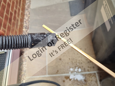
Sailing barge sails
Rick
It appears that in this photo there is a ruler of sorts? Using it along with the fill size ruler, measure the following:
Foot
Head
Luff
Leach
Send a photo of this when done.
Ron
🇨🇦 Ronald

1 day ago
Blog
Re: Fairey Faun - RC Installation
Hi Chris,
I think every one of your Fairey Marine models all count as a Classic Model Power Boat and all originate from the time period that we enjoy modelling (and then driving !).
As each one is completed, it would be really good to see them individually pictured with any additional info that could be of some interest.
I have also noticed the decline in the huge amount of interest and support that the Fairey Marine boats used to enjoy, but this could all change when people get to see your diverse collection of boats that this fine company produced over the years.
Picture of your boats "in action" do not need to show the boat going very fast - especially if they were never intended to be fast (like your river cruiser), but that does not lessen their interest.
Nice static pictures are in some ways even better as more of the model can be seen in greater detail, but both would be nice to see as they are all most definately Classic Model Power Boats.
Bob.
🇬🇧 zooma
1 day ago
Forum
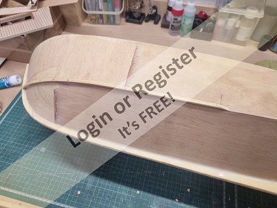
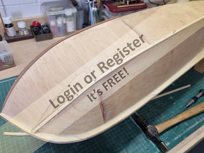
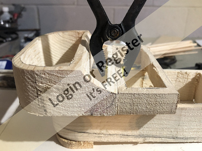
Sprite
I won't show any pictures of the thumb, but this is the device that chopped a lump out of it !
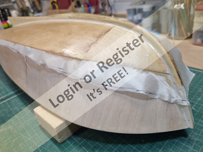
This is very good sharp clean cutting little plane that made light work of trimming away the keel and the doublers ready to fit the bottom skins.
The small accident was my fault entirely, I was trying to hold the frame of the boat against my chest with the left hand as I was planing it with the right hand and obviously failed to control either the boat or the plane adequately.
Not to worry, most of the woodwork washed up OK with clean cold water and so "alls well the ends well" as they say
Bob.
🇬🇧 zooma
2 days ago
Forum
Early Radio Control Experiences
As far as RC gear, I had a Derek Olley switch job which was excellent. Then an Acoms set and possibly another. Then I saw the Micron 6 ch. 27Mhtz FM kit. I bought and soldered up a 6 ch. Tx. and a rx. I subsequently made 3 more rx's and also converted the servo o/p sockets to current type.
At the time the Futaba rx. was all tuning coils and my one was 'difficult' The Micron rx. was excellent and easy to set up and use. This was all 27Mhtz FM and I have a few pairs of crystals for FM.
When the 35Mhtz band came out I bought a 27Mhtz FM Futaba M3 with rx. lovely thing and still use it. The rx. not so good.
The FM Futaba rx I sent off for repair to a specialist company for repair or to get it working. Putting a note with the Rx that it was 27Mhtz.
I got it back quite quickly but it did not work. I phoned the company and told them and also said it was tuned to 35 when I has specifically said it was 27. The guy at the other end hotly denied it and went on a bit about the company etc.
I let him finish and asked him, "Did he want the 35Mhtz crystal back that was in the rx.?"
It was retuned after I sent it back but it was nowhere near as good as the Micron one.
Roy
🇬🇧 roycv

2 days ago
Blog
Re: Extending the cable routes.
Not that your a masochist or anything, you just like doing 'a proper job'
🇬🇧 tonyb2

2 days ago
Forum
Motor Mounts
I generally 3D design and print my own motor mounts, servo mounts and most everything that goes inside the hull. The photos are my Graupner "Dusseldorf" fireboat under complete rebuild (if I can get back to it).
Even if you buy motor mounts you still need to fasten them to something. This method (3D work) is easier for me. Temporarily hold the motor(s) in place, take measurements, then make the mounts.
Lew
🇺🇸 LewZ

2 days ago
Blog
Re: Woodstock Research and Build, Errors and Blunders
RP!!! What a beauty and 100% museum scale. She's absolutely...
🇺🇸 jumpugly
2 days ago
Blog
Re: Classic Model Power Boats
Suzie Q.
Drawn up by Vic Smeed and featured in the March and April 1965 Model Maker magazine, the prototype for this model was built from balsa and controlled with a single channel radio.
I bought the plans and built mine from plywood as I wanted to power it with an ENYA 19 water-cooled glow plug engine.
The super little boat 27" long model of a "typical" (at the time) off-shore racer shape proved to be another winner from Vic Smeed that I enjoyed running along with another of his Classic Model Power Boats from that same time period - the Remora "steering boat".
Both of these two models have aged rather better than may have been expected when they were first penned, and both respond really nicely to being driven fast with a modern brushless motor !
Bob
🇬🇧 zooma
2 days ago
Forum
Double Jointed Universal Couplings
Have you tried TEMU as they are really good with both quality (check any referrals on the products) and delivery, certainly to New Zealand. Cheers Ian
🇳🇿 IanL1

2 days ago
Forum
How do you create the coiled ropes?
I created a very short video on rope coils hope it uploads OK. It should explain how I do it. I think with a bit of luck you can finish off the coils in different ways.
I have used this jig on a number 72 scale models.
Bob
🇦🇺 BobbyN

3 days ago
Forum
Animal and nature photos to enjoy.
Incredible, what a spectacle! Thanks for sharing.
🇩🇪 Wolle

3 days ago
|

New Member
Belgium
ArneV21 hours ago
New Member
United Kingdom
Juppy2 days ago
New Promotion
Chief Petty Officer 2nd Class
 RPLedm
2 days ago
New Member
United Kingdom
DavidC122 days ago
New Promotion
Chief Petty Officer 1st Class
BobbyN2 days ago
Birthday This Week
Turns 70
Nickthesteam3 days ago
New Member
United Kingdom
SimonH3 days ago
New Member
United Kingdom
tonyp33 days ago
New Promotion
Sub-Lieutenant
 Oxford-Dave
4 days ago
New Member
Spain
PedroG4 days ago
New Member
Norway
john-richards5 days ago
New Promotion
Rear Admiral
Nickthesteam6 days ago
New Member
United Kingdom
StephenB36 days ago
New Member
United Kingdom
allant17 days ago
New Member
United Kingdom
JeremyP7 days ago
New Promotion
Able Seaman
 Fogwall
7 days ago
New Promotion
Commander
DuncanP7 days ago
New Promotion
Able Seaman
ian j7 days ago
New Member
United States
MIke17 days ago
New Member
United Kingdom
WilliamW27 days ago
New Member
United Kingdom
davem28 days ago
Account Updated
Updated Signature
paull58 days ago
Account Updated
Updated 'About Me'
paull58 days ago
New Member
United States
RevellW8 days ago
Birthday This Week
Turns 70
SouthportPat8 days ago
Account Updated
Changed Avatar
Otto9 days ago
New Member
Canada
PEI9 days ago
New Member
Switzerland
Otto9 days ago
New Member
United Kingdom
RobS110 days ago
New Member
United Kingdom
coll35110 days ago
Birthday This Week
Turns 73
 Chris W
10 days ago
New Promotion
Chief Petty Officer 1st Class
algon11 days ago
New Member
United Kingdom
MikeD312 days ago
New Member
United Kingdom
Fogwall12 days ago
New Member
Ireland
DavidM1013 days ago
New Member
Canada
JohnD914 days ago
Account Updated
Updated 'About Me'
Millwall Steve14 days ago
New Member
United States
ezratic17 days ago
New Member
United Kingdom
PapaSmurf17 days ago
Account Updated
Updated 'About Me'
oefranz17 days ago
New Member
United Kingdom
TommyH18 days ago
New Member
New Zealand
poppy18 days ago
New Member
United Kingdom
paull518 days ago
New Member
Sweden
sorenJ18 days ago
New Member
Canada
oldflyer19 days ago
New Member
United Kingdom
FredE1119 days ago
Birthday This Week
Turns 78
jennyr19 days ago
Birthday This Week
Turns 78
Mike Stoney19 days ago
See More
Forum Topics
Nigel Trafford-Jones
Hi Zippy, he is on LinkedIn but don’t know if he is active.
If you want me to I will give him a negative write up on LinkedIn and see if that jolts him to contact you.
Ed
19 hours ago by 🇬🇧 EdW ( Commander)
Commander)
Hobby Chit Chat
3 Posts
6 Likes
6 Likes
Started
2 days ago
by zippy
2 days ago
by zippy
Latest
19 hours ago
by EdW
19 hours ago
by EdW
Question of the Day?
I no longer hear speeches that question the leading positions and this makes me think.
9 hours ago by 🇮🇹 AlessandroSPQR ( Fleet Admiral)
Fleet Admiral)
Website Related
5089 Posts
13024 Likes
13024 Likes
Started
3 years ago
by fireboat
3 years ago
by fireboat
Latest
9 hours ago
by AlessandroSPQR
9 hours ago
by AlessandroSPQR
And Now For Something Completely Different
HAYA Centurion Mk5.
Hi Lew,
My 3D printed Conquerer is not fully assembled yet, but I will loosely put the parts together later and take some pictures for you.
To compensate, here are some pictures of my 1/16 scale r/c Centurion that I built from the HAYA Centurion Mk3 kit and modified it to a Mk5 as used in the Berlin Brigade.
These tanks in the Berlin Brigade were unique in being painted in Olive Drab - all other Centurions and British tanks in Germany were painted in the more usual (at the time) Bronze Green.
It is not so far off the mark as the Conquerer was brought in to supplement the Centurions in Germany to boost the available NATO firepower, but was short-lived as the Centurion's own upgrades made the Conquerer redundant and saved the army having to carry spares and parts for two different types of main battle tanks (MBT).
I am still working on the weathering and final paint but I have some spray masks made so that I can airbrush on the unit markings and the name of the tank etc in due course
The tank has a revolving commanders cupola, metal tracks and sprockets, authentic Rolls Royce meteor engine sound with machine gun and main gun sound via a Clarke board and has engine exhaust smoke as well as gun flash and barrel smoke following each shot of the main gun.
Future plans include adding more powerful motors to drive the two steel gearboxes to help the tank when running across some of the more demanding terrain that it has to encounter.
My tanks are like my Classic Model Power Boats insomuch that they are not "shelf queens" - they are driven often and enjoyed - and worked hard.
Bob.
16 hours ago by 🇬🇧 zooma ( Rear Admiral)
Rear Admiral)
Hobby Chit Chat
19 Posts
60 Likes
60 Likes
Started
18 days ago
by zooma
18 days ago
by zooma
Latest
16 hours ago
by zooma
16 hours ago
by zooma
Tools
I used a David razor blade plane in my school days when I was shaping the aerofoil section of my control line model aircraft , and that would be over 65 years ago!
This plane took the single edge razor blades that were commonly available then, and I often held the blade in my hand to cut balsa wood as it cut better than the Xacto knives !
The David razor blade plane that I have now is probably a lot newer (maybe only 40 years old?), but I think the original one had a metal wing nut rather than the black plastic moulded one shown here.
I also had a small Xacto moulded plastic tool case that had a number 1 (small) , number 2 (medium) and number 5 (large) sized handles in it with a selection of different blades and a razor saw blade to fit the number 5 handle.
There is every possibility that the Xacto moulded "plastic" tool case was actually moulded in Bakalite as it was a bit fragile around the points where the metal hinges fitted........and sadly it has failed to survive!
The number 5 Xacto saw handle had a moulded handle on it and the razor saw blade that it took was very handy for cutting some of the hardwood engine bearers - but was not a patch on the Tamiya razor saws that I use these days.
In the Xacto moulded tool case was also this red cast iron miniature smoothing plane that came in handy when shaping leading edges although I always preferred to final shape these with sandpaper wrapped around a suitably size hardwood block.
This is my original Xacto miniature smoothing plane and so it is probably over 65 years old!
During my time at home I wanted to strip and clean these olde tools but until the wound on my thumb has mended a bit I am reluctant to risk splashing any oils etc into it, but if I can dig-out my pack of black plastic "mechanics" gloves, I may do it in-between time when waiting for the glue to dry as I continue t work on the Sprite Plus.
Xacto tools have been copied by several different manufacturers sine the 1950's, but I have never seen the Xacto miniature plane copied by anyone.
Bob.
11 hours ago by 🇬🇧 zooma ( Rear Admiral)
Rear Admiral)
Building Related
41 Posts
147 Likes
147 Likes
Started
18 days ago
by ChrisF
18 days ago
by ChrisF
Latest
11 hours ago
by zooma
11 hours ago
by zooma
I Hate Painting!
Wow, I read this & thought I must have typed it without knowing. I feel your pain. I have a boat built by my dad many years ago, & I am renovating it from years of sitting in top of a cabinet. Its a Billings kit & unfortunately the wood had dried out so much, there are lots of splits in the hull. So after methodically rubbing it back to bare wood, sorting it out, I am going through the exact problems with painting. Thank you for making me no longer feel alone in this issue.
15 hours ago by 🇬🇧 LazyFerret ( Recruit)
Recruit)
Building Related
1 Post
3 Likes
3 Likes
Started
1 day ago
by ChrisF
1 day ago
by ChrisF
Latest
15 hours ago
by LazyFerret
15 hours ago
by LazyFerret
|
|
Login To
Remove Ads
Remove Ads
Build Blogs
1 Post
0 Followers
1 Like
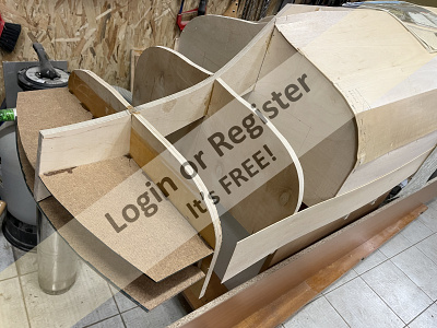
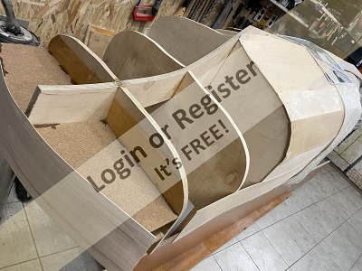
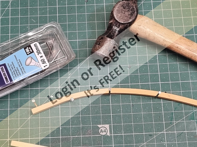
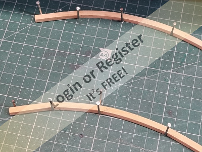
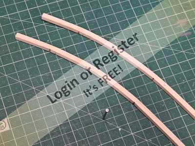
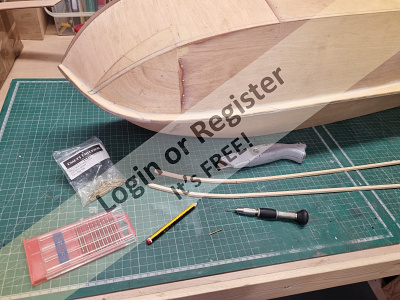
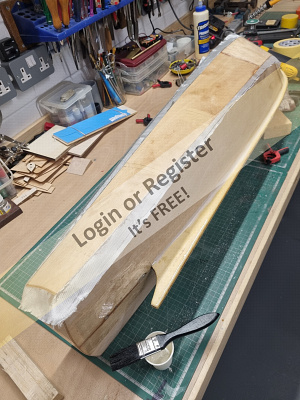
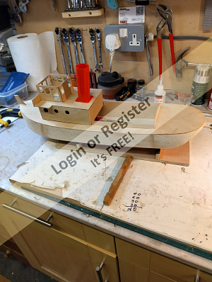
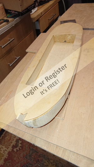
Fire boat Florián 1:7, Construction (second attempt) from scratch
Based on old and new photos, and based on previous experiences, I will show the progress of working on the model here.
So far, it's more of a carpentry job than a modeler's work..I am adding a photo of two more ribs - 26.5.2025. I glue the ribs right away, but I will cut or drill them as needed. Even though I already have one experience - it's not enough. Sometimes the right result is on the second or third try - but that doesn't bother me. I welcome any practice in this size of model.
🇨🇿 premecekcz

9 hours ago


0 Posts
0 Followers
1 Like
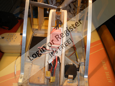
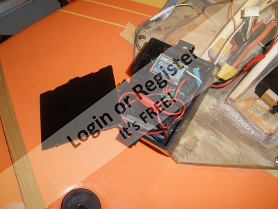
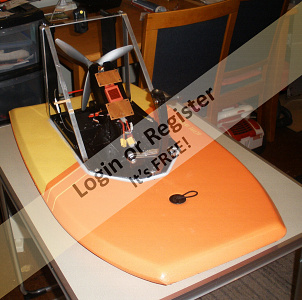
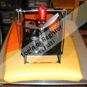
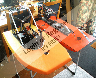
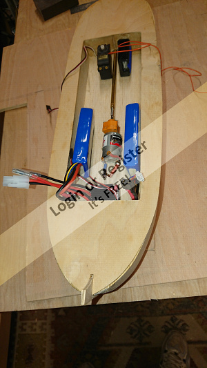
Cheap unsinkable airboat
For a bit of fun i decided to knock up another airboat for rescue and camera work. made from a $19 body board with a 3542 1000kv TGY outrunner running on a 4s Lipo, with a 10x6 pusher prop. Went fairly well on it's first test using only about 30% power, but needed some up thrust and rudder trim for much more throttle. Probably needs some small bottom strakes to limit the drifting tendency and make it easier to control, (did this with the first airboat which manages 30kph)
Could quite easily run on 3s for more economy, as it planes very easily. I got 20mins almost continuous running at the speed in the video, (on 30%) which is more than adequate, as it would be just idling around for videos. Quick to make and lots of fun. Motor mount screws onto 4 -30mm dowels epoxied into the body board.
JB
https://www.youtube.com/watch?v=EBcKXAVqrEE
🇳🇿 jbkiwi
15 hours ago


10 Posts
6 Followers
43 Likes
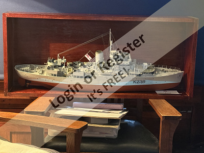
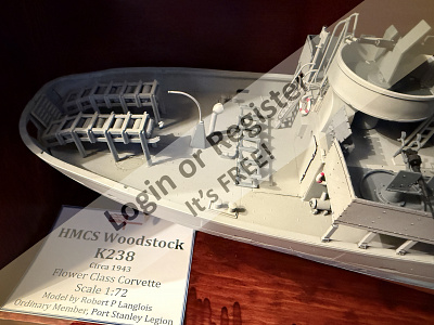
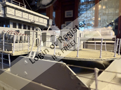
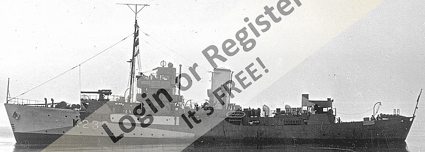
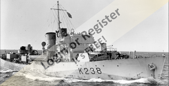
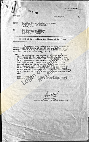
HMCS Woodstock from a Kitbashed Revell Flower Class Corvette
Starting the dig into the Ottawa Archives and The Great Lakes Museum in Kingston:
🇨🇦 RPLedm
2 days ago


19 Posts
22 Followers
230 Likes
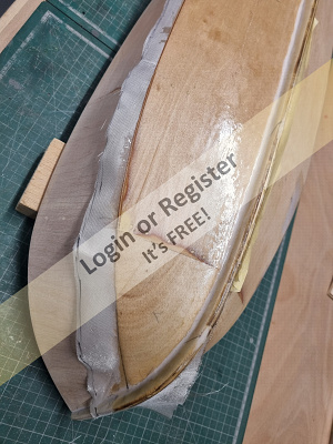
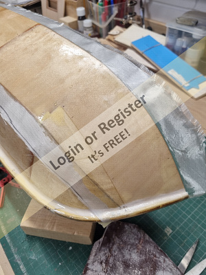
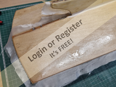
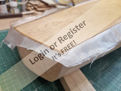
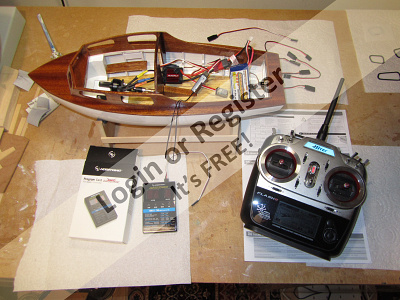
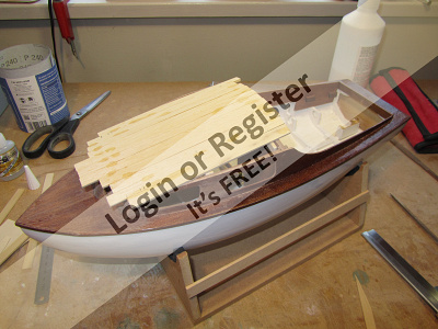
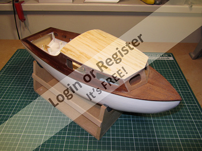
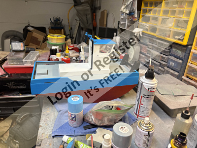
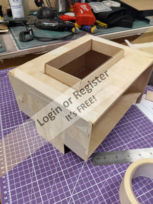
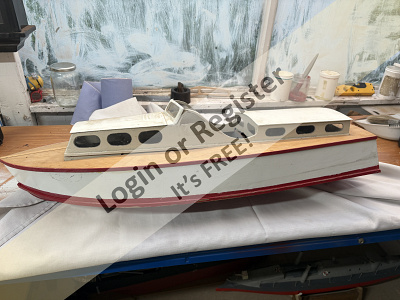
The VMW Marlin Cabin Cruiser by Robbob
The VMW Marlin Cabin Cruiser by Robbob
Preface.
At the time of writing, I’ve had the construction of this boat on ‘the back burner’ since July 2022. By then I had spent about two months on and off constructing the boat to a stage where I could consider applying a glassfibre cloth and epoxy finish to the hull. However I couldn’t spend any more time on the Marlin project as I had a more important project to undertake, which was to paint, decorate, refurbish and prepare our house for sale so that we could downsize and move to a new area now that our kids had all fled the nest.
Fast forward to today (mid-April 2025) and it’s taken a while to get the new house and gardens into shape and settle in, with the emphasis on converting my internal garage into a great new workshop, I can finally pick up from where I left off.
Introduction to the kit.
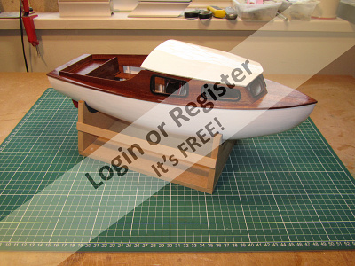
This new model is the latest undertaking by Vintage Model Works, now famous for their very popular models of the RAF Crash Rescue Tender and Thames River Police Boat kits which are based on old Aerokits and Veron designs.
The Marlin is a re-working of an original Veron design by the late Phil Smith in 1953. His son Colin Smith, who was also responsible for the re-design of the Thames River Police Boat, has made some changes to his father’s design to take advantage of more modern materials and production methods such as CNC and laser cutting.
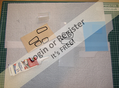
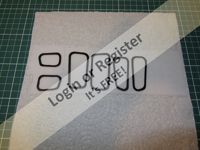
The photograph below is of a prototype built by Colin Smith to give you an idea of how the boat looks in finished form. And there is also a review of the Marlin that appeared in Model Maker magazine, November 1953.
The size remains at 36” and it employs the same construction method as the original. The spacious cabins of the boat makes it very easy to accommodate all the latest control hardware required, not that the original was lacking in that area even when the radio systems used valves and large batteries and the propulsion was usually IC or a large electric motor.
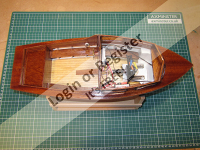
Even the pre-production sample the Vintage Model Works kit supplied to me is well presented with a full size drawing including a pictorial construction sequence and separate pages of building instructions.
All the required materials are supplied in quality ply, balsa, strip-wood and dowel including clear plastic sheets for the windscreens, and various white metal deck fittings. The builder is of course required to supply their own adhesives and paint of choice, as well as the propulsion, drive train and radio control gear. In the latter respect I will likely restrict control to throttle and rudder and not add any lighting or other features. That has already been done magnificently by Mike Turpin.
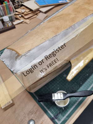
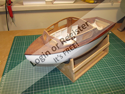
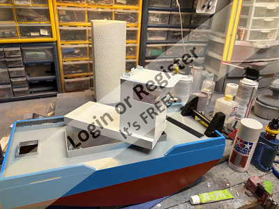
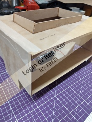
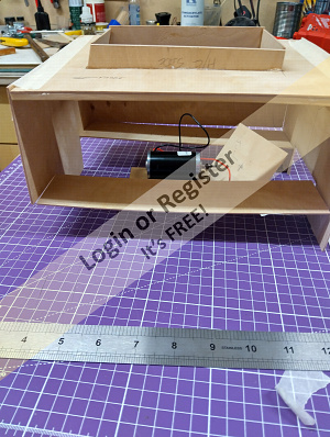
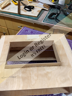
Construction.
As with the Thames river police boat, another Veron design, construction starts with the assembly of a box structure onto which formers and bulkheads are attached to make the basic hull shape.
I will be tackling this in the first part of my build blog which I hope you will enjoy following and I encourage you to ask questions, leave comments and hopefully some ‘likes’ as I make progress.
Robbob.
🇬🇧 robbob
2 days ago


30 Posts
19 Followers
237 Likes
Fairey Marine Builds
I haven’t done anything on my builds since before last Christmas for various reasons but am looking forward to starting again in the next couple of weeks.
I’ve been working on a number of builds for some years and not finished one yet! Main reason is that I reach a certain point, maybe something I’m hesitant about, and so start another! Which is the reason I’ve got five on the go.
I’m building all the classic Faireys; Huntsman 28, Huntsman 31 and Swordsman 33 and a rarer Huntress 23 with a stern drive and longer cabin. Also a River Cruiser 23 (the one and only full-size build was a prototype was based on a modified Huntress hull but with more freeboard which disappeared) and I have the plans drawn up to start a Fisherman 27 motor sailer and a Faun 17 river/lake cruiser. All builds are at a scale of 1:12.
The River Cruiser and Huntress are further on as they have had lake trials with the others being at the painting stage which I will be taking up again soon.
I use a Hitec Flash 8 Tx and Rx’s and Hitec servos with Overlander brushless motors (even in my slower models) and HobbyWing Quicrun and Seaking ESC’s along with LiPo batteries though will probably use NiMh in the Fisherman and Faun.
🇬🇧 ChrisF
2 days ago


7 Posts
8 Followers
48 Likes
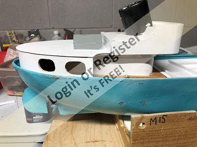
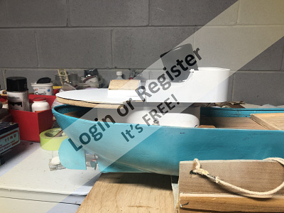
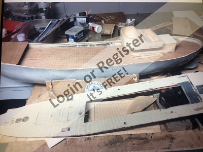
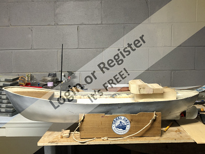
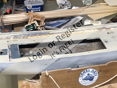
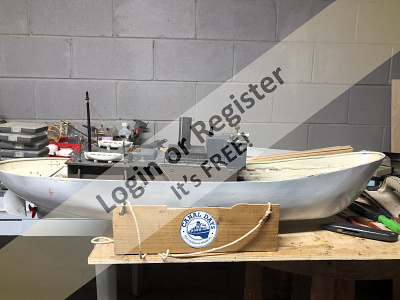
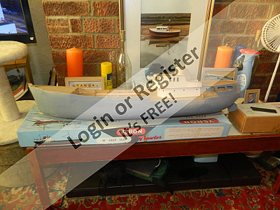
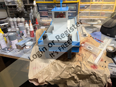
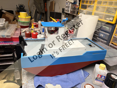
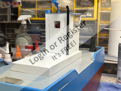
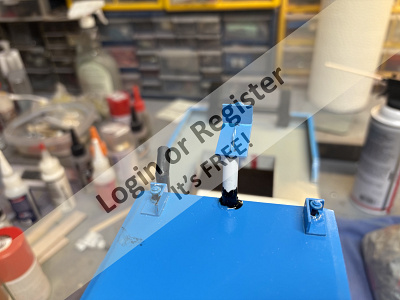
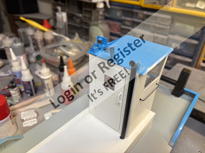
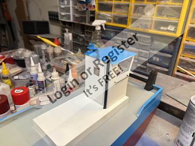
Trawler
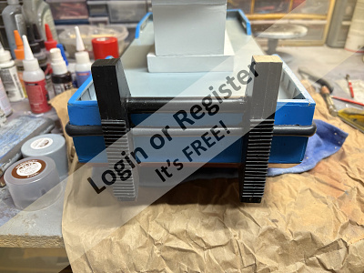
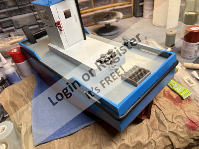
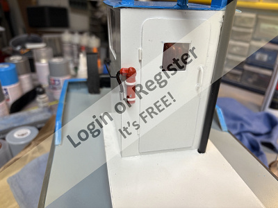
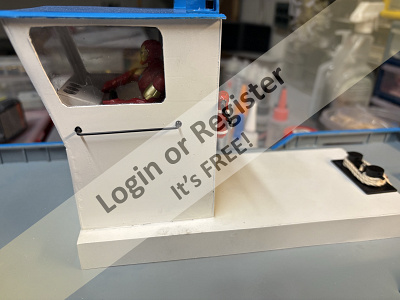
Saw this on my Facebook feed, and I'm a little bored, so I will try to convert one of my model boats to a deep-sea trawler. The first photo is mine. I need to rebuild the bridge layout & hopefully we will have a Trawler. To be continued, maybe.
🇨🇦 GARTH

5 days ago


10 Posts
11 Followers
96 Likes
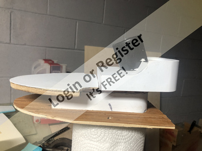
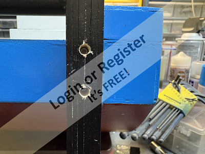
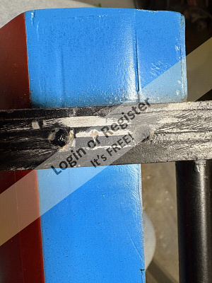
Another Springer tug!!
Hi y’all. Since Dickey has maidened I decided I wanted to do one more project before I attempt to overhaul my garage workshop. I’m thinking I’ll be down a month or more if I get done what I want to get done. In that vein, I’ve decided to attempt another Springer tug. Some years ago I built one before I really had ballasting down right..she ran okay, but I kept messing around with the ballast, epoxying it in, and when I tried to remove it to make changes I severely damaged the hull. So, I removed all equipment, fittings, etc and scrapped the hull. I’ve been wanting another go at it, so I ordered the Zippkits tugster, just the kit no hardware, and started to lick my calf over (old country phrase for a “do-over”)
I built the hull proper per the instructions, and that’s where that ends. I’m using a 4mm shaft, the smaller Robbe/Krick Kort nozzle, and a home made stuffing box. She will be powered by my fave working boat motor, the Zippkits 650 kv outrunner fed by 2 6 cell nimh in parallel.
My stuffing box is made up of a thick wall brass tube that accepts a Traxxas 4mm i.d flanged oilite bushing. The bushing is tapped in with a hammer, and I use an old 4mm shaft to make sure the bushings stay aligned as I install the other bushing. The 1mm thick wall allows me to drill a hole the same size as the brass I’m using for an oiling tube. I’ll grind down the fitted end just a bit to get a decent, thight mechanical joint. That way when I silver solder it in place it stays put and is a good strong joint. The reason I’m so picky is that I use a mini grease gun from Horizon Hobbies, I can old it in place and pump, and I get just a wee bit of grease showing at the bushing under pressure, that way I know darn well it’s full.
I used part of the keel parts to fit the tube, cutting it shorter to allow me to swing the Kort nozzle hard over to make it easier to change props without removing the Kort nozzle, depending on the size of the prop. I cut an oversized slot for the tube as I use solid couplers, and with the motor fitted I could get everything lined up and tack the tube in place with ca, that way I have no binding. I don’t like using universal joint couplers unless I really have to. I get my couplers from Servo City, as they are steel, use larger socket screws, and don’t have any runout. Very solid.
The kit uses a radio plate to to mount the servo, receiver and esc. I cut that down and built up a servo mount, and it’s installed on the same bulkhead shown in the manual, but I mounted it to the fwd side vs the aft as in the instructions. My deck opening is going to be different. I’m using Dubro pushrods, but good old Amazon was out of the ones with metal quick links, so I ordered the ones with nylon. I dug thru my junk box of hardware that I have been collecting since 95 or so, and I found gold!! A few Dubro and Sullivan threaded metal clevises, and some solder clevises too. I mounted the servo, made sure everything worked correctly, then uninstalled everything and gave the inside of the bow and transom and the bottom of the hull a coat of 30 minute epoxy.
That’s where she’s at now. I’m thing I’ll spray the rest of the inside of the hull with clear lacquer ro finish waterproofing, then I have to make a decision. I dont know if I need to glass this thing, or maybe glass the bottom and the just seal and paint the heck out of the sides, or….I’ve also heard that some people just epoxy coat the outer ull with thinned epoxy, then prime and paint. She’s gonn be a working boat, used as an emergency push boat when needed, so she needs to last…if I can get her ballasted properly this time, that is…
Cash
🇺🇸 Cashrc
7 days ago


3 Posts
4 Followers
11 Likes
Another Pusher Tug
While doing research for my Springer/Pusher tug I discovered these drawings David Metcalf’s Motorflot Pusher Tug and I had all the materials to build it so I put the other pusher I am building aside and started on this one. I am easily distracted
All the hull parts have been cut out one after yesterdays power outage, I will stat the assembly today.
Pictures to follow.
🇬🇧 EdW
9 days ago

5 Posts
6 Followers
22 Likes
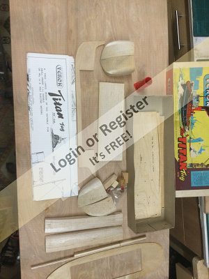
Titan Tug
As I promised here is where I am with the build of my Veron Titan Tug
🇬🇧 EdW
10 days ago

4 Posts
3 Followers
10 Likes
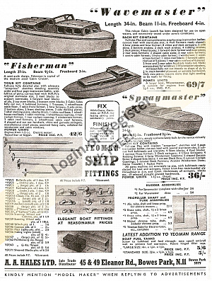
Wave master boat
This is a classic wave master it was built in the fifty's a nd a internet buy I have stripped out the rc engine and its tanks now on the research stage there are a few issues rear end smack thats had a poor repair done and the spray rails do not fit well of its history I know nothing
🇬🇧 Stephen T
12 days ago
1 Post
1 Follower
7 Likes
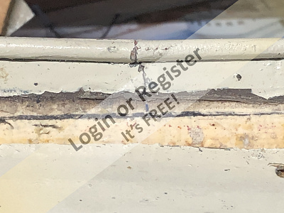
Original LesRo Sportsman Restoration.
The original shape LesRo Sportsman is a model that had eluded me for many years, but I always liked the look of it, so when one came up on eBay, I matched the opening price with my first bid, and ended up winning it as nobody else placed a bid.
It could well be that everyone else was a lot wiser than me, but I have ended-up with it and it will be a long-term restoration project that will have to be fitted in-between a lot of other build/repair work that I already have stacked-up waiting for my attention.
This boat came with a fitted glow-plug engine of unknown size or type, so the first job was to remove the engine, fuel tank and silencer etc to see just how bad and fuel soaked the inside of the hull was, and then try to work-out how to dry it out and make any repairs that may be needed.
Bob.
🇬🇧 zooma
16 days ago

9 Posts
11 Followers
88 Likes
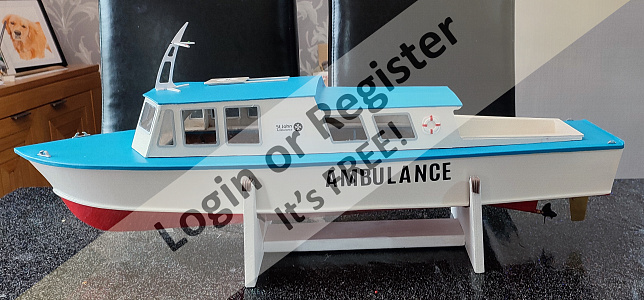
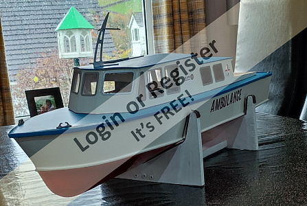
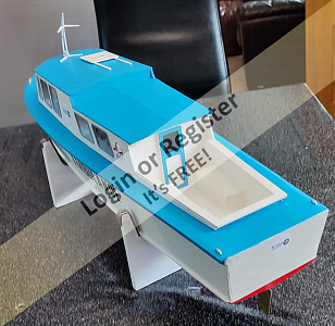
FLYING Christine II
This is a build of a HA-Kits Flying Christine II which is a model of the St. John's Ambulance service boat which is used to take patients from the Isle of Guernsey (UK) for treatment elsewhere - probably with more facilities! I'm getting my nearly twelve year old grandson to build it with just guidance from myself and I assisted with cutting of the tabs off the laser cut parts on the thicker plywood. We need to get the younger generation interested in our great hobby!
The box contains all the plywood laser cut parts on varying thicknesses of plywood. In addition there is a bag of plastic window frames and plastic window inserts. There is no propeller shaft, rudder or other bits to complete the model.
Construction so far seems to be fairly straight forward and it is something that my grandson is enjoying doing. It is the first model of any kind that he has built.
As he doesn't live near us he is here for just 10 days and we hope to get it completed by the time he goes home. The kit says use thick and thin cyno or Aliphatic glue. I have chose to use Aliphatic so we don't get little fingers stuck together! It will be slower but hope to speed up the process by starting building the cabin whilst the hull is fully curing before adding the skins - the order laid out in the instruction.
BEWARE when initially gluing both halves of the deck together it says you may strengthen the joint by gluing some scrap on the back of the joint. We unfortunately chose a piece about 2mm too long so later in the build it came into contact with one of the bulkheads - so we had to trim it back!
The only other thing was the instructions didn't clearly mention gluing two of the cabin bulkheads together to make one. After a bit of thought and looking at the cabin layout it became obvious that C2 and C3 needed to be first glued together. Having said that when attaching to the cabin frame C3 follows C1 (as one part) and C2 is then before C4!
Make sure you use plenty of masking tape to ensure that the cabin structure doesn't get glued onto the deck! See photos
So this is where we are at the end of Day 2 - more to follow!
Apologies in that the photos are not in the correct sequence!
🇬🇧 DuncanP
17 days ago


|
|

Media Gallery
SSMBC (Seminole, Florida) meet, Nov. 2, 2025
12 days ago by LewZ
Spooky - (Evening sail November)
15 days ago by philcaretaker
Gaff Rigged Bristol Pilot Cutter Autumn / Fall
18 days ago by philcaretaker
Only 2 days left
28 days ago by GARTH
Professional Photographer at Southport
1 month ago by SouthportPat
Filming over water
1 month ago by philcaretaker
"Sailor Sam" greets onlookers at the Sunday morning "Run In The Park".
2 months ago by philcaretaker
Light up the Night on the September 25th 2025 including safety cautions
2 months ago by GARTH
Second navigation (4 September 2025) to Lake Turano.
2 months ago by AlessandroSPQR
Maritime Drone
2 months ago by teledrone
Canadian Coast guard 44 Lifeboat
2 months ago by GARTH
War ship regatta
2 months ago by GARTH
|
|

Login To
Remove Ads
Remove Ads
Boat Clubs & Lakes
Recent Updates In Places

|
Buxton Model Boat Club
4 days ago by 🇧🇪 hermank (
Rear Admiral) |
|
|
Southport Model Boat Club
14 days ago by 🇬🇧 SouthportPat (
Commodore) |
|
|
BUXTON MODEL BOAT CLUB
15 days ago by 🇬🇧 philcaretaker (
Commodore) |
|
|
New Brighton Model Boat Club
26 days ago by 🇬🇧 zooma (
Rear Admiral) |
|
|
Wallesey Model Boat Club
27 days ago by 🇬🇧 SouthportPat (
Commodore) |
|
|

Upcoming Events

|
Nov
15 2025
|
Nov
16 2025
|
Model Boat Show
Ended 2 hours ago
|
|
|

Boat Harbour
5 Photos
7 Likes
My ARTR Plastic Yachts
I bought the HydroPro Affinity not long after I started the hobby to learn to sail and do some club racing. It is 650mm long and complies with the DF65 racing regulations. Like the more common DragonForce 65 it was built by Joysway and was introduced as a slightly cheaper model but as it used many parts from the DragonForce I doubt it was very viable and wasn't available for very long. I built it with the B Suit of sails for windier days.
A few years later I wanted something a little more competitive (the HydroPro is quite beamy) and so bought a DragonForce 65 which I fitted with the A suit of sails for less windy days - saves having to change sails!
🇬🇧 ChrisF
7 days ago
0 Attributes
5 Comments
3 Photos
7 Likes
Wavemaster HMH boat winter restoration project
Got this 1950s model boat on line website I have been after a vintage wave master for a while she has had a rear end smash so a bit of repair work there and the top assembly doesn't quite fit more on this in due course mine doesn't look like the photo off line
In side the boat says Harvey A Adams 17 June 1954
🇬🇧 Stephen T
22 days ago
5 Attributes
2 Comments
19 Photos
8 Likes
RSO Steyr 1/6th German ww2 field tractor (yes not another NONE boat) although it could do a small be
This is my scratch build German WW2 field tractor, ongoing process but does drive and currently undergoing a gearbox rebuild as the old drill motors felt the pain on tight turns.. Also has new prototype body from the Version 3 which I think only a few were ever in filed use.
Has sound and lights. A combination of 3d printed parts and aluminium, all the drives shafts are with bearings along with the road wheels.. Still a way to go, but time ain't the issue I hope. Although nothing is a given ..
🇬🇧 Northernflotsam
22 days ago
0 Attributes
2 Comments
3 Photos
1 Like
VOLVO C304 1/10th
Heres some shots of the Volvo C304 scratch build, more complete right now that current pictures but have been busy.. life eh
6x6 conversion complete via 3d printed parts and 2 FTX chassis as donors.. drives quite well .
🇬🇧 Northernflotsam
22 days ago
0 Attributes
1 Comment
1 Photo
8 Likes
Landrover 101 1/10 scale
Not a boat or is it.. landrover 101 FC 1/10th scale rc.. build from rc crawler chassis kit and scratch build body .. works fine and sounds pretty good
🇬🇧 Northernflotsam
22 days ago
0 Attributes
3 Comments
1 Photo
8 Likes
In progress Bearospace EMMA
this one is now almost ready for the epoxy skin, sail winch to fit and thats still on the bench as of today, started this as Ive never done a working sail model..
🇬🇧 Northernflotsam
22 days ago
0 Attributes
3 Comments
1 Photo
6 Likes
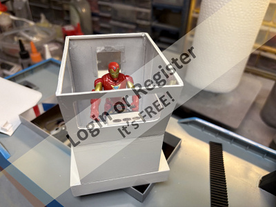
1/12 figure conversion ..
I converted a figure (spock) in a lifeboat coxwain for a friend.. greenstuff miliput and apoxy.. old but thought I pop it up
🇬🇧 Northernflotsam
24 days ago
0 Attributes
3 Comments
3 Photos
4 Likes
Vintage Hull rescue and re-imagining
Got the hull for this form a person whom had it in a junk pile, glassed inside with crap and car filler. Did my very best to rescue the hull and spent a whie pulling and rotary tool removing as much as I could, had a few ideas what to creat from it so as is a WIP.
Its beeb a while since on here but now things are beginning to find a level we'll see how I go
🇬🇧 Northernflotsam
24 days ago
0 Attributes
4 Comments
13 Photos
13 Likes
Northumberland cobble static model
This was built from the enterprise cobble drawings. I started this as a learning process
🇬🇧 Northernflotsam
24 days ago
0 Attributes
7 Comments
|
|
How-To Articles
Essential or useful tools and utensils for the ship modeler. A final appendix lists the most common
Revised 19 days ago
By AlessandroSPQR
stop email notifications
Revised 22 days ago
By Ace23
painting epoxy over Humbrol and varnish enamels
Revised 3 months ago
By roycv
Cardan joint, Homokinetic joint, universal joint. Problems related to the junction between the engin
Revised 5 months ago
By AlessandroSPQR
various electrical connection diagrams for two motors
Revised 7 months ago
By tomarack
Lifeboats or work boats?
Revised 10 months ago
By AlessandroSPQR
Permanent magnet brushed electric motors. Main features. Basic elements of distinction. How to evalu
Revised 10 months ago
By AlessandroSPQR
When wooden planking the sides of hulls What Glues are you using?
Revised 1 year ago
By bruce1946
Fibreglassing a wooden hull
Revised 1 year ago
By DuncanP
Building Veron Marlin
Revised 1 year ago
By jonb
|
|

Login To
Remove Ads
Remove Ads
Model Boats Website
This is the alert text. You can customize this text to be as long or short as needed. The modal height will adjust accordingly.
🛍️ Basket
Main menu transported here on mobile
Login
Create New Account
Trending Topics
Members Online
Forum
Nigel Trafford-Jones
EdW
19 hours ago
Forum
Question of the Day?
EdW
19 hours ago
Forum
And Now For Something Completely Different
ChrisF
1 day ago
Forum
Tools
ChrisF
1 day ago
Forum
I Hate Painting!
ChrisF
1 day ago
Forum
Sailing barge sails
Ronald
1 day ago
Blog
Re: Fairey Faun - RC Installation
zooma
1 day ago
Forum
Sprite
zooma
2 days ago
Forum
Early Radio Control Experiences
roycv
2 days ago
Blog
Re: Extending the cable routes.
tonyb2
2 days ago
Forum
Motor Mounts
LewZ
2 days ago
Blog
Re: Woodstock Research and Build, Errors and Blunders
jumpugly
2 days ago
Blog
Re: Classic Model Power Boats
zooma
2 days ago
Forum
Double Jointed Universal Couplings
IanL1
2 days ago
Forum
How do you create the coiled ropes?
BobbyN
3 days ago
Forum
Animal and nature photos to enjoy.
Wolle
3 days ago
Forum
A little bit of luck
Ronald
3 days ago
Blog
Re: Jetty for model boats
ChrisF
4 days ago
Forum
Dutch sailing barge
AndyB2
4 days ago
Forum
Back to Model Boat Building (replaced 3D printers)
LewZ
5 days ago
Forum
Post-Scotland inspiration
Ronald
5 days ago
Blog
Re: A few details
wingsounds13
5 days ago
Blog
Trawler
GARTH
5 days ago
Forum
EMYC Annual Dry Dock Dinner & Annual Swap Meet
AlessandroSPQR
5 days ago
Event
Model Boat Show
PhilH
6 days ago
Harbour
Re: My ARTR Plastic Yachts
jumpugly
6 days ago
Blog
Re: Aerokits Sea Commander. Strange Handling ?
zooma
7 days ago
Forum
Fairey Swordsman Plans
ChrisF
7 days ago
BOATSHED
Commander
2,671 Points
1 second ago
RPLedm
Chief Petty Officer 2nd Class
339 Points
13 seconds ago
RossM
Captain
3,093 Points
21 seconds ago
Steves-s
Chief Petty Officer 2nd Class
421 Points
24 minutes ago
roycv
Admiral
9,818 Points
43 minutes ago
Ronald
Fleet Admiral
12,576 Points
1 hour ago
GARTH
Captain
3,856 Points
1 hour ago
Rowen
Captain
3,547 Points
1 hour ago
ChrisF
Rear Admiral
5,583 Points
2 hours ago
RonH
Warrant Officer
793 Points
2 hours ago

zippy
Master Seaman
123 Points
2 hours ago
RM
Recruit
0 Points
2 hours ago
thadlietz
Petty Officer 1st Class
299 Points
3 hours ago

d dubya
Recruit
6 Points
3 hours ago
ekoral
Master Seaman
128 Points
3 hours ago
DWBrinkman
Commodore
4,262 Points
3 hours ago
GaryLC
Captain
3,449 Points
3 hours ago
Chum444
Captain
3,794 Points
3 hours ago
AustinG
Warrant Officer
664 Points
4 hours ago
zooma
Rear Admiral
5,619 Points
4 hours ago
DuncanP
Commander
2,506 Points
4 hours ago
OliverK
Recruit
0 Points
4 hours ago
Steamrod
Recruit
7 Points
5 hours ago
AndyB2
Chief Petty Officer 2nd Class
349 Points
5 hours ago
RogerA1
Warrant Officer
680 Points
5 hours ago
radu022003
Recruit
7 Points
5 hours ago
mturpin013
Admiral
8,495 Points
6 hours ago
RonB
Recruit
0 Points
6 hours ago
Oxford-Dave
Sub-Lieutenant
1,220 Points
6 hours ago
dash8man
Able Seaman
26 Points
7 hours ago
premecekcz
Master Seaman
114 Points
7 hours ago
IORYellow40
Recruit
0 Points
7 hours ago
hermank
Rear Admiral
5,226 Points
8 hours ago
Monty6
Recruit
0 Points
8 hours ago
AlessandroSPQR
Fleet Admiral
11,884 Points
9 hours ago
luckyduck
Lieutenant
1,834 Points
9 hours ago

Robidoo
Recruit
0 Points
9 hours ago
Softie
Able Seaman
22 Points
10 hours ago
Landlubber
Recruit
0 Points
10 hours ago
SouthportPat
Commodore
4,769 Points
10 hours ago
Capt Bob
Recruit
0 Points
10 hours ago
trowley
Recruit
0 Points
10 hours ago
JEANFRANCOIS G
Recruit
0 Points
10 hours ago
robertc3
Recruit
3 Points
11 hours ago
PEI
Recruit
0 Points
11 hours ago
JOHN
Midshipman
1,094 Points
11 hours ago
Hhager2
Sub-Lieutenant
1,458 Points
11 hours ago
Wolle
Commodore
4,810 Points
11 hours ago
AdrianG
Recruit
10 Points
12 hours ago
PeteJev
Petty Officer 2nd Class
162 Points
12 hours ago

Login To
Remove Ads
Remove Ads
🏠
Home
Home
📰
Trending
Trending
💬
Forum
Forum
🗝
Login / Join
Login / Join
|
Cookies are used for ads personalisation.
By using this website you agree to our use of cookies. More Info |
Main Menu
🚤 Model Boats
• Forum
• Build Blogs
• Media Gallery
• Boat Clubs & Lakes
• Events
• Boat Harbour
• How-To Articles
• Useful Links
• The Games Chest
This Website
🔍 Search
📝 Guestbook
👨👩👧👦 Members (1,803)
📣 Support
Hobby Supplies
🛍️ Online Shop
Login
🗝 Login
🗝 Create New Account
▼
Media Gallery
X
1 of 4
► |
◄ |
Media Viewer
^
_
X
Share
X
Flag Inappropriate Post
X
| Select Reason | |
| Sexual content Includes graphic sexual activity, nudity, and other sexual content. | |
| Violent or repulsive content Violent or graphic content, or content posted to shock viewers. | |
| Hateful or abusive content Content that promotes hatred against protected groups, abuses vulnerable individuals, or engages in cyberbullying. | |
| Harmful dangerous acts Content that includes acts that may result in physical harm. | |
| Child abuse Content that includes sexual, predatory or abusive communications towards minors. | |
| Promotes terrorism Content intended to recruit for terrorist organisations, incite violence, glorify terrorist attacks, or otherwise promote acts of terrorism. | |
| Spam or misleading Content that is massively posted or otherwise misleading in nature. | |
| Infringes my rights Privacy, copyright and other legal complaints. | |
Basket Updated
X
Loading...
Loading
Loading Uploader...