|||
|
|
🗝 Login
🤖 Create Account
Main Menu
🚤 Model Boats
• Forum
• Build Blogs
• Media Gallery
• Boat Clubs & Lakes
• Events
• Boat Harbour
• How-To Articles
• Plans & Docs
• Useful Links
• The Games Chest
This Website
🔍 Search
📝 Guestbook
👨👩👧👦 Members (1,789)
📖 Quick Site Guide
📣 Support
👥 Membership
Hobby Supplies
🛍️ Online Shop
Not Registered
Go AD FREE & get your membership medal
BRONZE
Less Ads
SILVER
GOLD
Ad Free
Cancel
Anytime
Anytime
£2.50
£4.50
£6.50
Subscribe
Go AD FREE & get your membership medal
BRONZE
Less Ads
SILVER
GOLD
Ad Free
For A Whole Year!
£25
£45
£65
Donate
You Will Be Helping Towards:
Domain Fees
Security Certificates
iOS & Android App Fees
Website Hosting
Fast Servers
Data Backups
Upkeep & Maintenance
Administration Costs
Without your support the website wouldn't be what it is today.
Please consider donating towards these fees to help keep us afloat.
Read more
All donations are securely managed through PayPal.
Many thanks for your kind support
Without your support the website wouldn't be what it is today.
Please consider donating towards these fees to help keep us afloat.
Read more
All donations are securely managed through PayPal.
Many thanks for your kind support
Join Us On Social Media!

|

|

|
Download The App!
Login To
Remove Ads
Remove Ads
Login To
Remove Ads
Remove Ads
🏝️ About This Website
☝️ Terms of Service
🔏 Privacy Policy
Model Boats Website
Model Boats Website
Home
Forum
Build Blogs
Media Gallery
Boat Clubs & Lakes
Events
Boat Harbour
How-To Articles
Plans & Docs
Useful Links
The Games Chest
Login To
Remove Ads
Remove Ads
Trending Now
Blog
Re: The tub test
Hi Alessandro.
My tub test was in the garage in a low light, hence the shade change, but it's in the photos only.
Thanks for the well wishes. I'll need some luck moving forward!
🇺🇸 jumpugly

30 minutes ago
Forum
Peterd has passed away quietly this evening
I have received word that our colleague has quietly passed away. I don’t know his family other than Marilyn is his wife and there are family members too.
Remember them in your thoughts and prayers over these coming weeks.
Respectfully
Ronald
🇨🇦 Ronald

2 hours ago
Blog
Re: Making the Rear Hatch
Looking great, Robbob.
It’s always tricky to design a hatch that’s secure enough to withstand the wake generated by other models.
I used six 5 mm magnets, with a piece of galvanized steel on the hatch, and I’m hoping this setup will perform as well as yours.
🇺🇸 chugalone100

10 hours ago
Event
Edina Model Yacht Club at the Minneapolis Boat Show
I understand that the space is quite crowded, which is precisely why I would greatly appreciate seeing your setup.
🇺🇸 chugalone100
12 hours ago
Forum
Identify model
Hello Andy-W.,
Perfect winter work!
I would love to bring something like this to life too. But here at our club, the harbor construction is coming to an end.
Then I'll have time again for my “cellar skeletons.”
I'm excited to see your work! Good luck!
See you soon, your Michel-C.
PS: With a little imagination, you can achieve anything, as I did with my Dolores, a sternwheel steamboat.
🇨🇭 Mike Stoney

12 hours ago
Forum
Question of the Day?
Come on down to longest answer wins at least it gives me a fighting chance of knowing it
Phil uk
🇬🇧 PhilH

16 hours ago
Blog
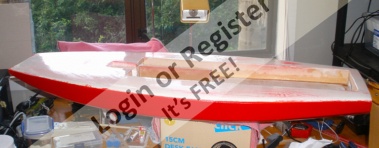
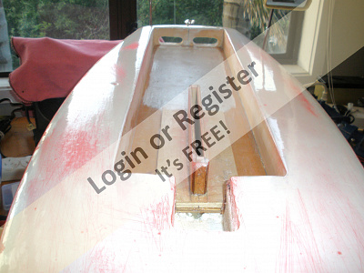
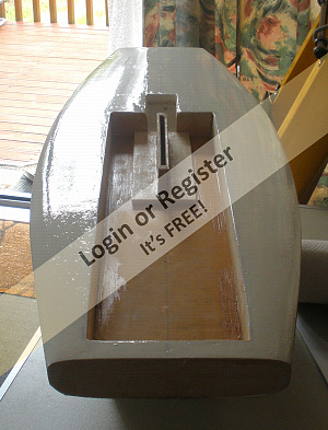
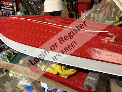
New Moth MKII semi scale yacht
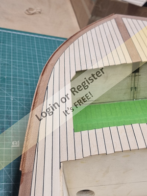
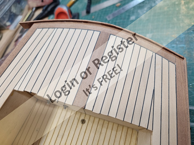
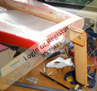
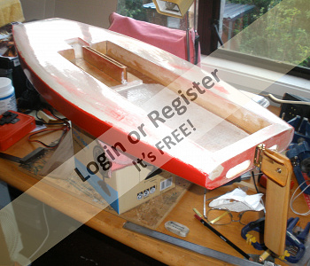
Hull's back to red paint now after the Zinsser coat which fixed the fisheyes. Added some mahogany trim to the rudder stock, and have now cut out the self draining slots in the transom, (i think it's going to need them) The foam between the cockpit ply and transom will need filling and coating round the inside of the drains. Still have the deck to paint (over the white resin) and a veneer to go on the transom (varnished). After that,- fittings. Decided to leave the rudder unpainted, looks ok as is I think.
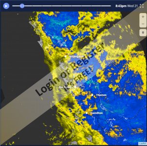
Rough weather slowing things down at the moment, heavy rain, landslides (unfortunately people missing,) slips everywhere, flooding etc . It's supposed to be summer !
JB
🇳🇿 jbkiwi
18 hours ago
Forum
Meet Selma from Norway 🇳🇴
Great stuff Ron! Many thanks to John!!!
🇺🇸 jumpugly
2 days ago
Blog
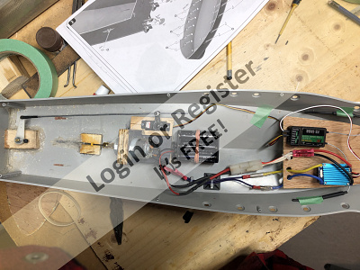
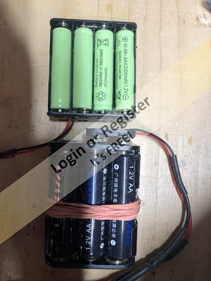
Re: Vosper
Doing a fine job Garth. Yes the torpedo tubes will hide the nuts. I see you went for a different battery.
I still don’t like the way you chose to put your receiver and ESC in the bow under the deck.
It is s easy to place them in your well of the wheelhouse. I know from our conversation this week that you are not going to be detailing it as I did. So, why not use the space?
🇨🇦 Ronald
2 days ago
Forum
Adhesives
You might look into this product it might work for your needs https://www.amazon.com/Welding-Repair%EF%BC%8CCar-Automotive-Plastics%EF%BC%8CMetals%EF%BC%8CStainless-Steel%EF%BC%8CAluminum%EF%BC%8CIron%EF%BC%8C1-76/dp/B0CYGZ5GYF/ref=sxbs_sbv_search_btf?content-id=amzn1.sym.37132d36-da68-4ed0-8d23-842f0825e4d6%3Aamzn1.sym.37132d36-da68-4ed0-8d23-842f0825e4d6&crid=29HX8HGY0UGZ4&cv_ct_cx=3m%2Bscotch-weld%2Bdp420ns&keywords=3m%2Bscotch-weld%2Bdp420ns&pd_rd_i=B0CYGZ5GYF&pd_rd_r=e9075470-a50a-4de2-a892-3238ccd96e80&pd_rd_w=G3CIe&pd_rd_wg=U9X5I&pf_rd_p=37132d36-da68-4ed0-8d23-842f0825e4d6&pf_rd_r=DKFEBY70BCKMBASKXD1A&qid=1769126599&sbo=RZvfv%2F%2FHxDF%2BO5021pAnSA%3D%3D&sprefix=scotch%2BDP420n%2Caps%2C159&sr=1-1-a61ee601-6e56-4862-a8a2-1d3da5a5406f&th=1
🇺🇸 bruce1946

2 days ago
Forum
Sailing at the Toronto Boat Show
The Toronto International Boat Show (the official name of the the show) has been running every January at the CNE grounds since 1959. It went virtual during Covid.
🇨🇦 ScouterChil

2 days ago
Blog
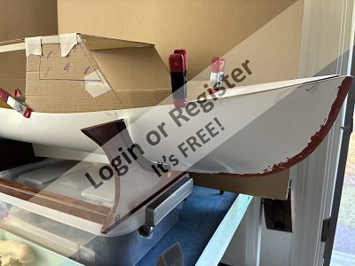
Last gasp before maiden splash in warm weather
A few more things done before we head to the warm weather.
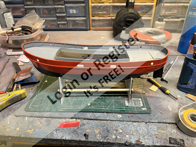
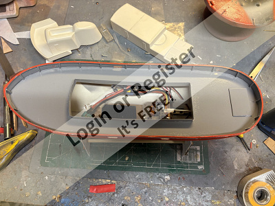
1. Into the ballast test tank the other day. No leaks & initial ballast set. 16.5 oz in the stern. With 12 os NIMH an additional 9os of lead ballast. Right now float weight about 4 lbs. Might be a bit light.
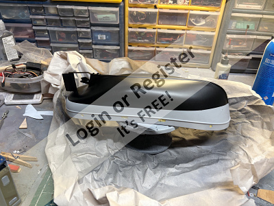
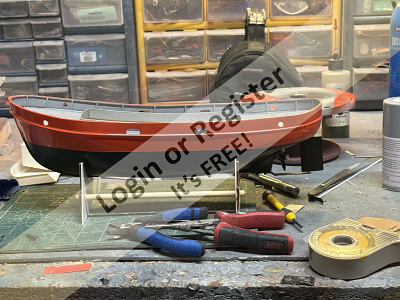
2. Gloss black hull, white anti foul paint on bottom & red boot top.
3. Profile view.
🇺🇸 Chum444

3 days ago
Forum
How much is too much? (If it ain't free and I need to volunteer then I ain't joining.)
Lew i think that that is part if the problem. Too much offered to the youngsters. I started in the early sixties no mobile phones, most people didn’t even have a television, no internet, no asocial media. I m a (strong) believer that we have hit the bottom of the curve and that i will go up again. I spoke to parents at the pond on sunday and one of the questions was “ can we come back with the kids” because they have never been so laid back with the sailing. Times will change in the other direction( one day )
🇧🇪 hermank
3 days ago
Forum
motor for large paddle steamer. Advice required
here is the progress on the front deck. Still trying to sort out a place to work on the 3 metre 35kg hull!
🇬🇧 Hermione

4 days ago
Blog
Re: Fairey Fisherman 27
Jig Saw.
I think that the "foot" that rests on top of the wood is more or less essential on a jig saw to hold the wood down onto the surface plate when the action of the blade is trying to lift it up with every stroke!
The "foot" on my Hegnar jig saw is much smaller than yours, and often as the wood is turned, the "foot" looses contact with the wood and I have to press the wood down firmly to hold it onto the saw's baseplate (at the same time as guiding it) - with mixed results!
It is certainly much easier to "cut to the line" when the wood that is being cut it held firmly against the base plate of the jig saw.
Bob.
🇬🇧 zooma
4 days ago
|

New Member
United Kingdom
 NeilP1
6 hours ago
New Member
United Kingdom
IanH57 hours ago
New Member
France
hercule11 hours ago
New Member
United Kingdom
SimonC2 days ago
New Member
United States
PaulD102 days ago
New Member
Argentina
ScoutS2 days ago
New Promotion
Able Seaman
 Kennybeck
2 days ago
New Member
United Kingdom
snah733 days ago
New Promotion
Master Seaman
ScouterChil3 days ago
Birthday This Week
Turns 87
geraldl3 days ago
New Member
Australia
PeterJ53 days ago
New Member
Canada
dond13 days ago
New Promotion
Sub-Lieutenant
bruce19463 days ago
New Member
United Kingdom
Amanda K3 days ago
New Promotion
Master Seaman
merchant674 days ago
New Member
Indonesia
BayoeB4 days ago
New Promotion
Leading Seaman
Hermione4 days ago
New Member
United Kingdom
RichardW5 days ago
New Member
Australia
GaryPArmstrong5 days ago
New Member
United Kingdom
DavidR45 days ago
Birthday This Week
Turns 82
Peejay6 days ago
New Member
Spain
JessO6 days ago
New Member
United Kingdom
HarryE6 days ago
New Member
United Kingdom
CliveO6 days ago
New Member
United Kingdom
DouglasG7 days ago
Birthday This Week
Turns 65
Cashrc7 days ago
New Member
United Kingdom
nicholasa8 days ago
Account Updated
Changed Avatar
PhilH8 days ago
New Member
Vietnam
Bung8 days ago
Birthday This Week
Turns 55
Aerodecked8 days ago
New Promotion
Leading Seaman
lukeH8 days ago
New Promotion
Commodore
GARTH9 days ago
New Member
United Kingdom
Adrian7pt9 days ago
New Member
United Kingdom
Sean10 days ago
Birthday This Week
Turns 74
DaveH210 days ago
New Member
New Zealand
KevinH110 days ago
Account Updated
Changed Avatar
lukeH10 days ago
New Member
United States
JJFlanagan10 days ago
New Member
United Kingdom
twilight10 days ago
New Member
United Kingdom
richardl411 days ago
New Member
United Kingdom
lukeH11 days ago
New Member
United Kingdom
hunting12 days ago
New Member
Turkey
ilkers12 days ago
New Member
United Kingdom
davidt612 days ago
Account Updated
Changed Avatar
 BOATSHED
13 days ago
New Member
United Kingdom
JoeS313 days ago
New Member
United Kingdom
SkyrayM13 days ago
New Member
Australia
MauriceP13 days ago
See More
Forum Topics
Peterd has passed away quietly this evening
I have received word that our colleague has quietly passed away. I don’t know his family other than Marilyn is his wife and there are family members too.
Remember them in your thoughts and prayers over these coming weeks.
Respectfully
Ronald
2 hours ago by 🇨🇦 Ronald ( Fleet Admiral)
Fleet Admiral)
Non-Hobby Chat
1 Post
0 Likes
0 Likes
Started
2 hours ago
by Ronald
2 hours ago
by Ronald
No Replies Yet
Identify model
Hello Andy-W.,
Perfect winter work!
I would love to bring something like this to life too. But here at our club, the harbor construction is coming to an end.
Then I'll have time again for my “cellar skeletons.”
I'm excited to see your work! Good luck!
See you soon, your Michel-C.
PS: With a little imagination, you can achieve anything, as I did with my Dolores, a sternwheel steamboat.
12 hours ago by 🇨🇭 Mike Stoney ( Rear Admiral)
Rear Admiral)
Building Related
5 Posts
19 Likes
19 Likes
Started
5 days ago
by AndyW
5 days ago
by AndyW
Latest
12 hours ago
by Mike Stoney
12 hours ago
by Mike Stoney
Question of the Day?
Come on down to longest answer wins at least it gives me a fighting chance of knowing it 🤣🤣
Phil uk👍
16 hours ago by 🇬🇧 PhilH ( Lieutenant)
Lieutenant)
Website Related
5433 Posts
13656 Likes
13656 Likes
Started
3 years ago
by fireboat
3 years ago
by fireboat
Latest
16 hours ago
by PhilH
16 hours ago
by PhilH
Edina Model Yacht Club at the Minneapolis Boat Show
I understand that the space is quite crowded, which is precisely why I would greatly appreciate seeing your setup.
😎
12 hours ago by 🇺🇸 chugalone100 ( Lieutenant Commander)
Lieutenant Commander)
Event
0 Posts
31 Likes
31 Likes
Started
1 day ago
by DWBrinkman
1 day ago
by DWBrinkman
Latest
12 hours ago
by chugalone100
12 hours ago
by chugalone100
Meet Selma from Norway 🇳🇴
Great stuff Ron! Many thanks to John!!!
👍😊
2 days ago by 🇺🇸 jumpugly ( Admiral)
Admiral)
Hobby Chit Chat
3 Posts
14 Likes
14 Likes
Started
2 days ago
by Ronald
2 days ago
by Ronald
Latest
2 days ago
by jumpugly
2 days ago
by jumpugly
|
|
Login To
Remove Ads
Remove Ads
Build Blogs
27 Posts
26 Followers
368 Likes
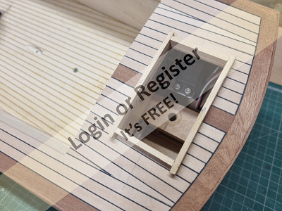
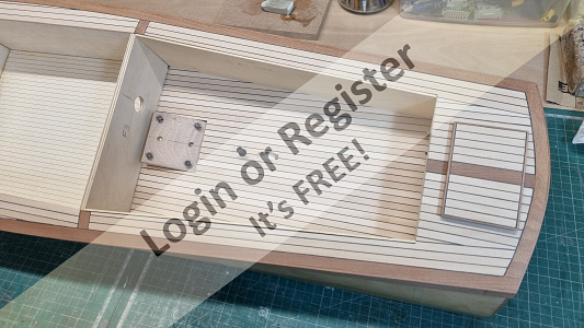
The VMW Marlin Cabin Cruiser by Robbob
The VMW Marlin Cabin Cruiser by Robbob
Preface.
At the time of writing, I’ve had the construction of this boat on ‘the back burner’ since July 2022. By then I had spent about two months on and off constructing the boat to a stage where I could consider applying a glassfibre cloth and epoxy finish to the hull. However I couldn’t spend any more time on the Marlin project as I had a more important project to undertake, which was to paint, decorate, refurbish and prepare our house for sale so that we could downsize and move to a new area now that our kids had all fled the nest.
Fast forward to today (mid-April 2025) and it’s taken a while to get the new house and gardens into shape and settle in, with the emphasis on converting my internal garage into a great new workshop, I can finally pick up from where I left off.
Introduction to the kit.
This new model is the latest undertaking by Vintage Model Works, now famous for their very popular models of the RAF Crash Rescue Tender and Thames River Police Boat kits which are based on old Aerokits and Veron designs.
The Marlin is a re-working of an original Veron design by the late Phil Smith in 1953. His son Colin Smith, who was also responsible for the re-design of the Thames River Police Boat, has made some changes to his father’s design to take advantage of more modern materials and production methods such as CNC and laser cutting.
The photograph below is of a prototype built by Colin Smith to give you an idea of how the boat looks in finished form. And there is also a review of the Marlin that appeared in Model Maker magazine, November 1953.
The size remains at 36” and it employs the same construction method as the original. The spacious cabins of the boat makes it very easy to accommodate all the latest control hardware required, not that the original was lacking in that area even when the radio systems used valves and large batteries and the propulsion was usually IC or a large electric motor.
Even the pre-production sample the Vintage Model Works kit supplied to me is well presented with a full size drawing including a pictorial construction sequence and separate pages of building instructions.
All the required materials are supplied in quality ply, balsa, strip-wood and dowel including clear plastic sheets for the windscreens, and various white metal deck fittings. The builder is of course required to supply their own adhesives and paint of choice, as well as the propulsion, drive train and radio control gear. In the latter respect I will likely restrict control to throttle and rudder and not add any lighting or other features. That has already been done magnificently by Mike Turpin.
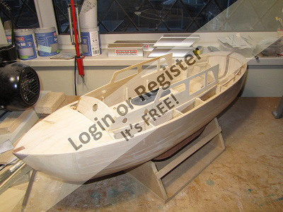
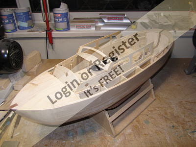
Construction.
As with the Thames river police boat, another Veron design, construction starts with the assembly of a box structure onto which formers and bulkheads are attached to make the basic hull shape.
I will be tackling this in the first part of my build blog which I hope you will enjoy following and I encourage you to ask questions, leave comments and hopefully some ‘likes’ as I make progress.
Robbob.
🇬🇧 robbob
13 hours ago


7 Posts
9 Followers
54 Likes
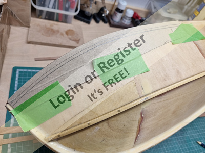
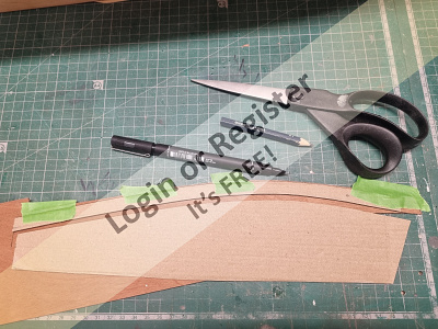
New Moth MKII semi scale yacht
Haven't built anything for a while due to lack of space (too many models) but the urge to build something was too great. After looking at many options, I decided to go with something 'easy' to build. I found some full size plans for an Australian MkI Moth which I'm building to a MKII (double chine) style.
I'm building in foam and glass again to make things easier. It's 850mm long and 310 wide which is roughly 1/4 scale (original is 11 ft)
Started by converting all the lofting measurements on the redrawn 1953 plan to metric and dividing them by 4 to get the scale.
Next was creating the ply deck, then contact gluing onto it a piece of dense 50mm building polystyrene. This was then shaped with a surform file and the chines shaped afterwards using eyeometry. Then the 10mm deck foam was glued on so the deck sheer could be shaped.
Next the cockpit foam was routered out, and basswood sides and inner transom piece epoxied in. After that, the ply outer transom piece and hardwood nose block was epoxied on.
The centerboard case upper and lower ply braces were routered out (using the mill and a 1/2" slotting bit) large enough to accept the case sides, leaving enough room for the 6mm aluminium keel (can't use a centerboard for obvious reasons) which will have to have a bulb fitted.
A rebate in the bottom of the hull was routered out for the lower c/board brace. These braces are needed to form part of a box structure with the floor and cockpit sides which the c/board can lever on. Once everything is eventually glassed in, it will make it very strong unit, so the foam will just be the shape surrounding the box, and not having any strain put on it. The ply deck will take the strain of the stays/mast.
The cockpit floor was cut, and will be slotted the same as the braces, then the c/board case will be built.
The mast on this is 1.486m tall, - sail is -luff -11.295, foot 609mm, so quite large for a small boat. The full sized boat is a lot of fun to sail, so this model will be interesting to sail. Unfortunately, without the human input required, and being a performance boat, it may assume the attributes of a submarine in a stiff breeze, - time and testing will tell.
The basic mast was made from 12mm ally tube, boom from 10mm. Sail pattern was cut from art card to the plan. All laid out on the floor to get an idea of what it will look like.
PDF is the history of the Moth. There were a number of versions round the world as it went along,- scow, international moth (dinghy type) and todays high speed foiling moth.
Lots more to do yet
JB
2025 world champs, off the Whangaparaoa peninsula, just up from where I live.
https://www.youtube.com/watch?v=FuLhJ-yRLmc
https://australianclassicdinghynetwork.org/moth
https://www.youtube.com/watch?v=wWkd2e8apSI
https://www.moth.asn.au/
https://www.youtube.com/watch?v=gAifFN0RJ0M
🇳🇿 jbkiwi
18 hours ago


18 Posts
18 Followers
182 Likes
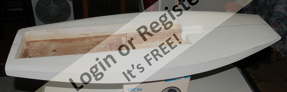
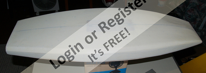
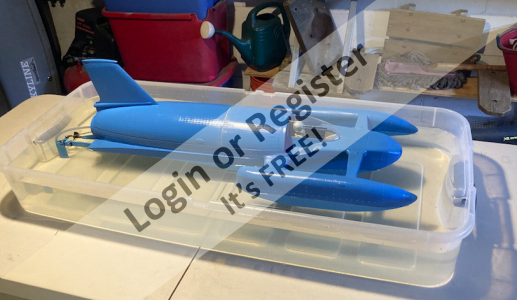
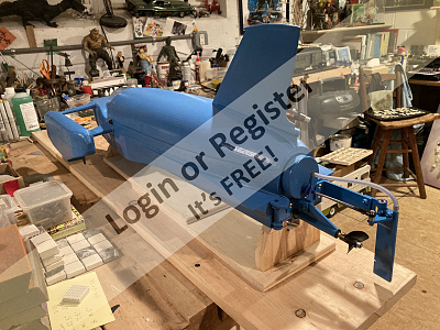
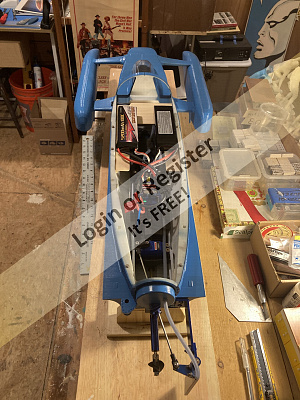
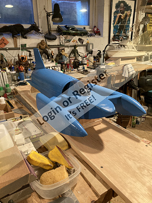
Bluebird k-7
Hello all! Before my two week sojourn out to California starting tomorrow...
Here she is, all 31 inches and 4.8 pounds of 3D printed 1/10th scale madness. And the questions are starting arise after more than a few hours spent in research. How to get her to plane even close to scale?
1) EDF? Probably not, actually I don't think even a 90mm fan, (which will, in fact, push a faomy jet) will ever get this boat to plane.
2) Prop? Maybe with dual 6s and a killer motor, monster cooling etc. But, nowhere near scale with a big prop hanging out the back.
3) Turbine? probably yes, but way out of my league in mechanicals and $$. There will be tons of head-scratching my quickly balding head on this experiment.
This is going to go on the shelf for the long haul as my freighter needs finishing and the big Sterling Chris Craft Corvette is screaming at me. But, off to Cali for now...I will drop some pix from time to time of our travels.
Best to all!
🇺🇸 jumpugly
1 day ago


4 Posts
3 Followers
21 Likes
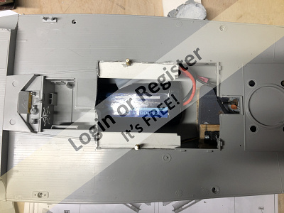
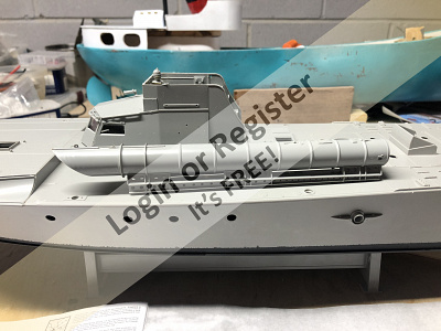
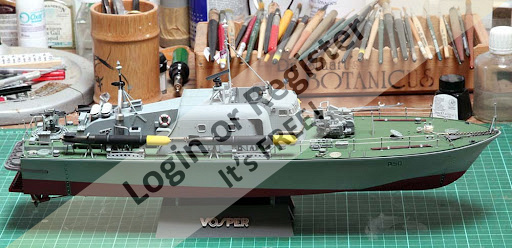
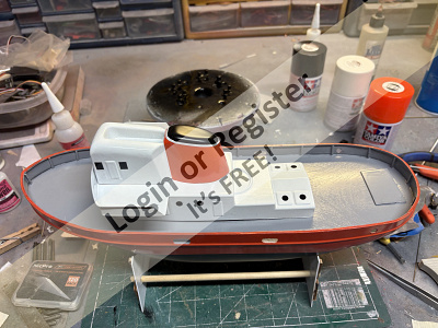
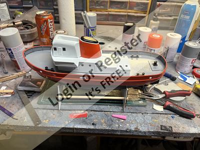
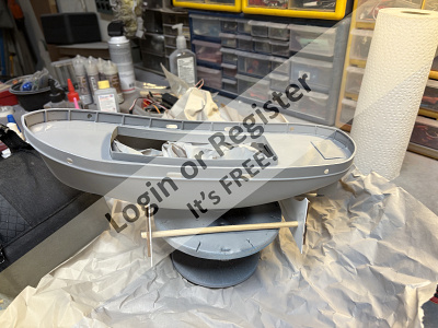
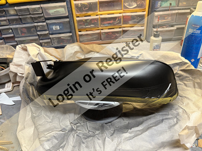
Vosper
Today was another part constructed. The motor mount is built, the propeller shaft and the propeller is installed need to wait till the glue sets and then I'll glue the motor in place.
🇨🇦 GARTH
2 days ago


7 Posts
5 Followers
47 Likes
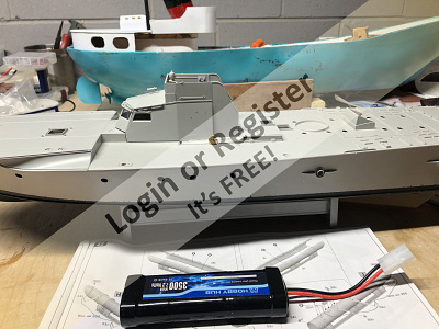
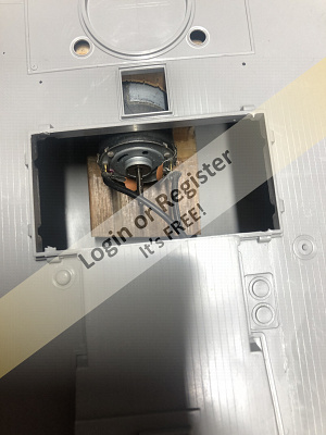
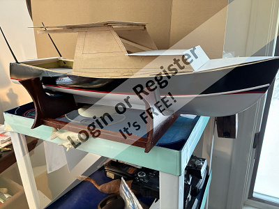
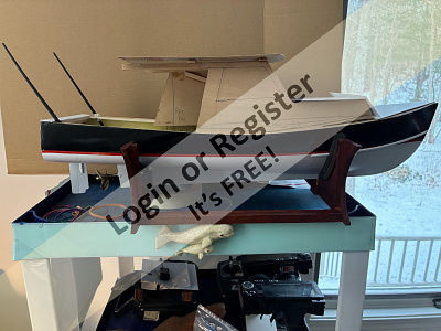
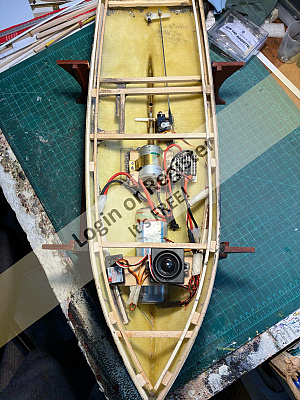
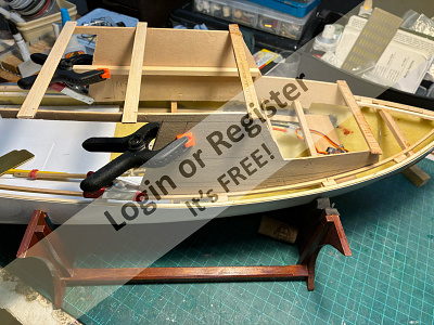
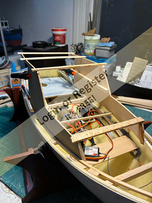
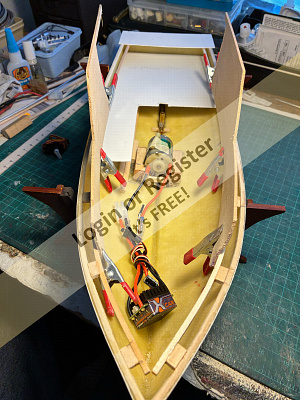
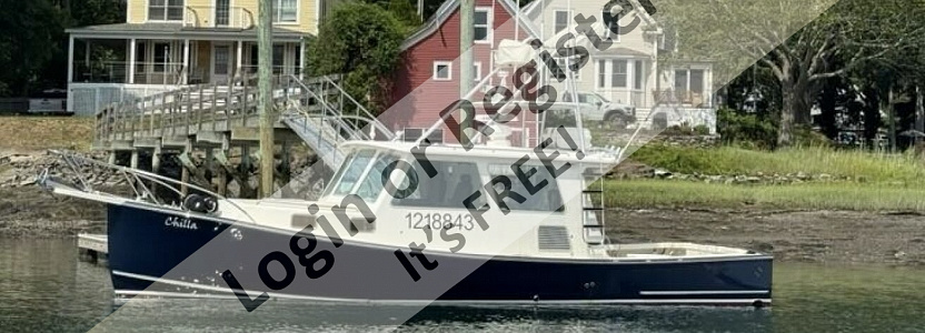
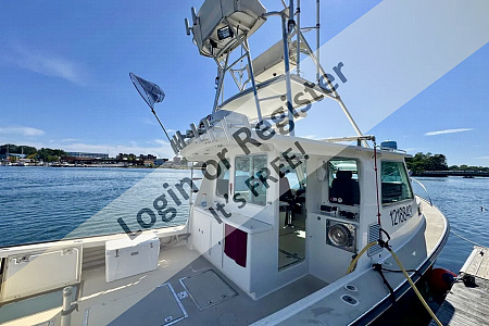
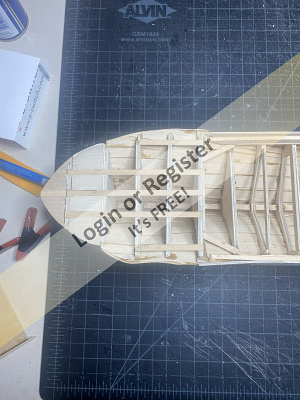
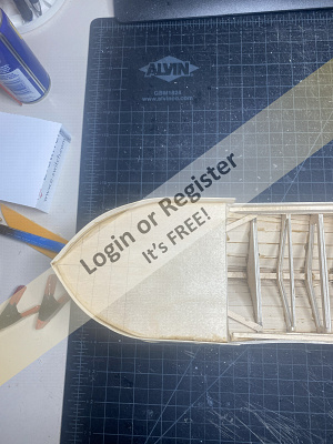
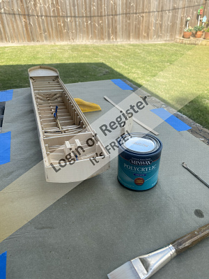
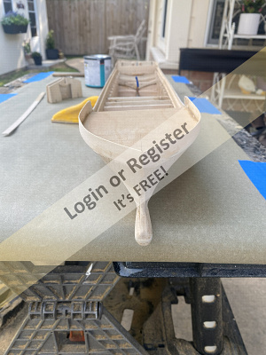
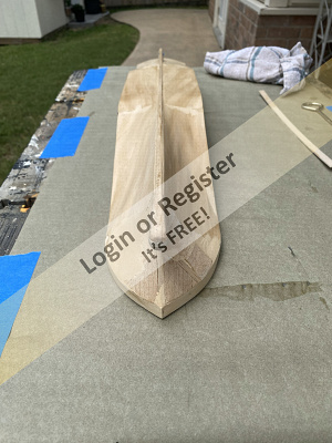
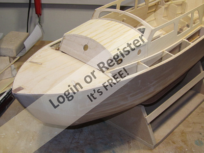
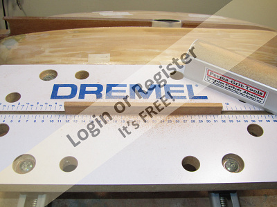
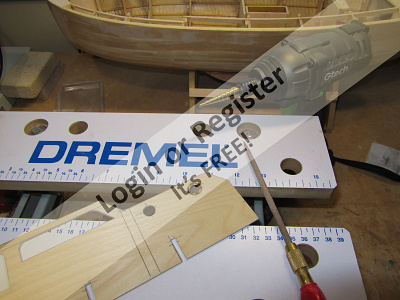
36 ft Northern Bay sport fisherman
The Northern Bay lobster and sport fishing boats are built in Qgunquit, Maine. Known as Down East boats they are semi-displacement hulls. They are very good sea boats stable in heavy seas. Compared to semi-vee hulls common to many other sport fisherman boats in the U.S. the Down East hulls tend to be wet boats. As with everything else, boat design is always a compromise.
1&2 The inspiration
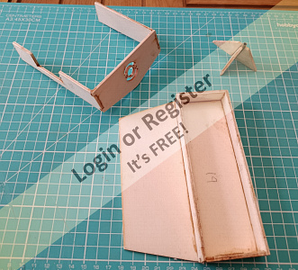
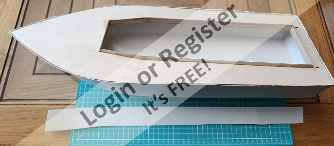
3&4 Beginning steps
🇺🇸 Chum444
3 days ago


1 Post
2 Followers
8 Likes
LISA M Motor Yacht
I've bought the above kit to keep me busy during these dark dank winter months. Originally I had planned to build a 880mm (34.6") Bluebird of Chelsea plank on frame kit. It is a famous pleasure craft built for Sir Malcolm Campbell and took part in rescuing soldiers from the beaches of Dunkirk under 'Operation Dynamo' in 1940. Unfortunately much to my bitter disappointment only the larger 52" version now is available which is too big for myself.
I'm hoping some kit builder will make a kit of this craft at about 36" so in the meantime here goes with LISA M
The kit has an ABS hull (a bonus for my hands these days!) and laser cut plywood parts. The kit also comes with an electric motor so all you need is a servo and speed control plus the usual R/C gear and battery.
A set of English instructions were also provided which are a reasonable translation with the odd error here and there! I feel they could be a bit more specific in places so study the photos.
The ABS hull comes with about 1 1/4" (about 300mm) extra height above the deck level which needs cutting down to be about 2mm above the temporary fitted deck level. This wasn't that easy but in the end I used a pair of tin snips to cut it which proved to be better than using a Stanley Knife. I have drilled and filed the holes in the ABS hull for the prop shaft tube and rudder tube. I've now assembled the deck coaming, motor mount, battery box and supports for the rudder tube. Next job is to waterproof the deck on both sides, and all the other assembled plywood parts. Having seen another blog, I've decided to strengthen the wood around the rudder tube by using an offcut from the wood provided for the boat stand. I will smooth the edges when the glue has set!
🇬🇧 DuncanP
5 days ago
5 Posts
5 Followers
46 Likes
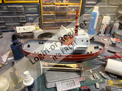
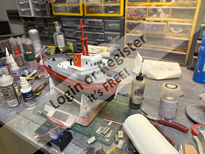
Graupner Pollux
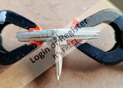
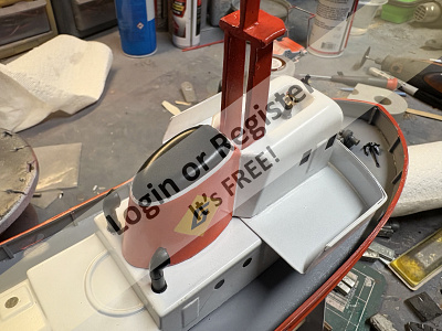
Hi y’all..it’s been a minuet since I’ve been on here. Getting ready for Christmas, the annual NTMS Christmas party, work, etc. I haven’t been at my bench for a few weeks, so I decided to drag a simple kit out of my stash and build it up…the Graupner Pollux.
This kit has been gone thru, some of the vac formed parts have been cut out but not finished, but it’s very buildable. First thing I had to do is build a stand. I pulled my trusty Ryobi scroll saw out from its hiding spot under the bench, got it set up, then the blade broke…and I couldn’t remember where I put my spare blades. So I built the stand up using plasticard for the uprights which I reinforced with 1/8 in ply strip, and used dowels to connect them together. I then looked at the kit and plans.
I did not have anything similar to the Speed 180 gearbox called for, so after I trimmed and sanded the hull I made up a motor mount for a 28mm outrunner. The motor I’m using is a little hotter than I would like, it’s 750KV, which is not a “hot” motor in any stretch but is a little hotter than I would have liked…but it’s in my stock, so I used it. The shaft was missing from the kit, so I had an 1/8 in I.D Dumas tube and shaft that I cut down to suit. I have a few 3 blade props in the right size for this boat, they’re set up for a drive dog or pin style shaft. They are made for a 3 mm shaft, so it was easy to clean out with a 3.2 (1/8) drill bit to fit my chosen hardware. I also am using a rudder from my parts stock, which I started to mount in the original location, didn’t like that so I moved it aft a bit to give a little more clearance for prop installation. The original hole is filled from the inside by the rudder tube support, the rest of the fill will be done later. After I got every thing ready I checked fit and alignment then glued every down. I then built up a servo mount and did a Buick install and test on the linkage, after that I glued down a battery floor.
That’s where’s she’s at now, I’m going to get the ESC and receiver mounted using Velcro, and once I’m statisfied that I can access them via the hatch I’ll start on the deck.
Cash
🇺🇸 Cashrc
6 days ago

1 Post
4 Followers
8 Likes
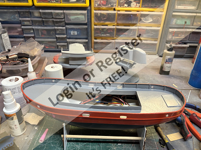
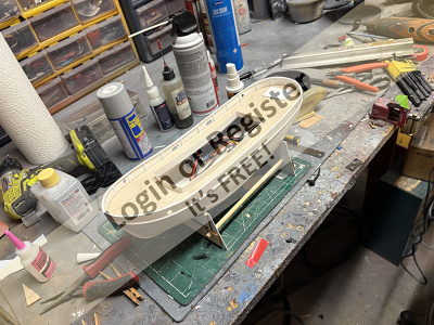
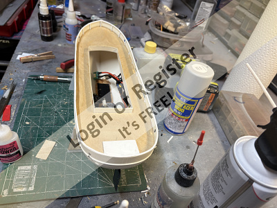
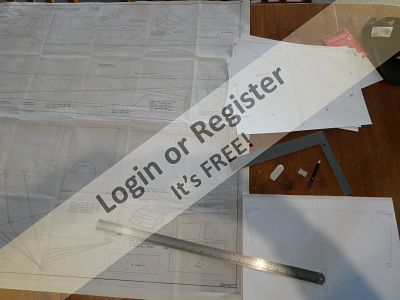
VIC SMEED'S VIVACITY
Hi all,
just posting a summary of (mainly) previously posted pics to kick off this build log and show progress to date since I first started researching the building of this 'leviathan' last year.
I'm currently at a stage where I have acquired the necessary propshaft/tube/propellor assembly and awaiting delivery of my chosen powertrain. The timber for most of the build has been sourced, so now I have finished other projects, all that really remains is to get on with it!!
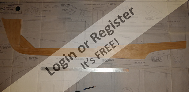
1)The plan...
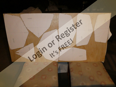
2)Drawing bulkhead and keel templates from plan
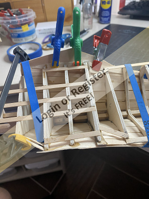
3)Bulkhead paper shapes stuck to 3/8 ply - I chose to make the bulkheads slightly thicker for extra gluing area and because I need to have ply-skin joins across certain bulkhead positions as standard modelling ply lengths do not go to 54". Some of these may have lightening holes cut in them for better internal access to equipment - haven't decided yet.
4)bulkheads cut out and trimmed/notched for stringers. Waiting for keel cut out, as a couple of issues regarding installation of the prop tube into the keel pieces have arisen; I need to accommodate the two oilers somehow, and the original keel pieces need to have another piece added to support the prop shaft all the way to the prop bearing - I'll post details when I've sorted it out...I hope
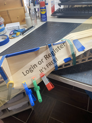
5)Original 10mm pine keel pieces cut out and assembled over plan - not yet glued up as an extra piece still required
6),7) & 8) Lots of spruce strips!! - spliced together to make up pieces approx. 70" in length for 3/16x3/8 chine stringer laminations, 1/4sq. sub-stringers, 3/6 sq spray rails and keel doublers.
9)18" 3-bush 3/8dia prop tube with oilers/tubes at two bearing positions, 3" diameter 3 blade propellor fashioned from 1mm brass sheet to be fitted to M5 thread on 3/16 steel shaft. I had this specially made up by Bill Nordmeyer who owns SAB Model Boat Fittings - thanks Bill!
The brushless motor and speed controller should be arriving in the next week or two. When they do, I intend to set up an engine/propshaft test to see what the performance specs are like prior to installing the tube in the keel. Once this has taken place I'll be able to post again.
Until then , best regards,
Nick
🇳🇿 Nick Ward

7 days ago


5 Posts
9 Followers
33 Likes
A Banana Boat??!
Happy Groundhog Day fellow model boaters. Seemed like a good day to start a build blog after the weather we have been having here in SE Texas. From hurricanes to snow fall, now nice sunny temps in the 70's.
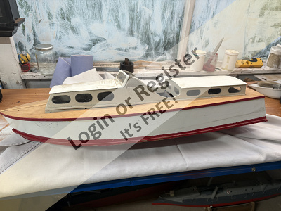
I asked my grandson earlier this summer what boat would he want me to build next. Without hesitation, he said a cargo ship showing me a picture of a Maresk Lines container ship in a children's picture book. I thought about this one for several weeks wondering how to build a realistic replica of something that large. My dry dock isn't very big, and the Admiral frowns on large models. One morning at breakfast I was peeling my banana, and I realize the perfect boat. A quick google search verified my thinking of the perfect cargo ship.
I have lived in this area all my life, and my first job was in the small gulf port town of Freeport, Texas. In the early 80's it basically only served the shrimp boat operators and commercial fishermen as well as a few cargo ships for Dow Chemical and the like. The size does not compare to the Port of Houston or even Galveston. However, in the 90's the Dole Fruit Company started operations delivering containers of tropical fruit for distribution to the US.
At that time I was commuting to Houston for work, and would see the Dole container trucks on the road and would chuckle to myself "must be a banana boat in port!
The Dole company just celebrated 30 years of service in Freeport, and in 2023 launched two sister container ships, the Aztec and Maya, specifically for the Gulf of Mexico deliveries. These are smaller ships which I estimate carry only about 500 containers.
Since I could not find any plans on the internet for a smaller container ship, I decided to make my own. From pictures of the Aztec, I free handed a graph paper drawing of what I intended to build, and when satisfied, I produced a CAD version in Autosketch.
The attached pictures are of the Aztec in port at Gulfport MS.. The Maya being built in drydock. My hand drawn rendering on graph paper, and a .PDF of the cad version with bulkhead detail.
The model ship will be about 26.5 inches long with a width of about 4.5". I plan to have a brushless motor driving a 1 inch 5 bladed brass prop.
Chris
🇺🇸 cjanik001

10 days ago


2 Posts
4 Followers
12 Likes
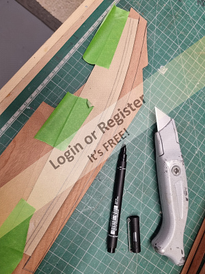
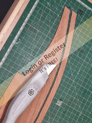
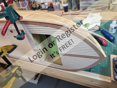
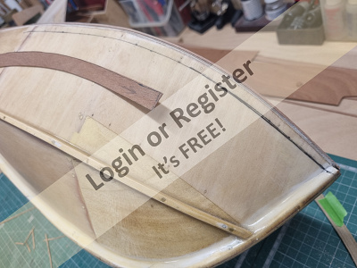
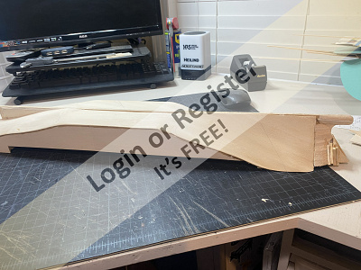
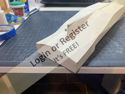
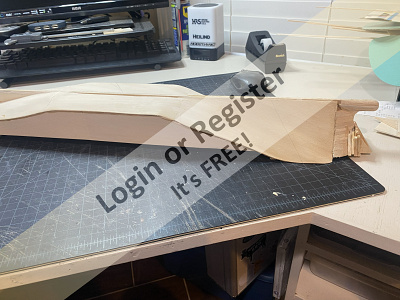
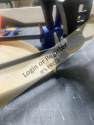
Fairey Fisherman 27
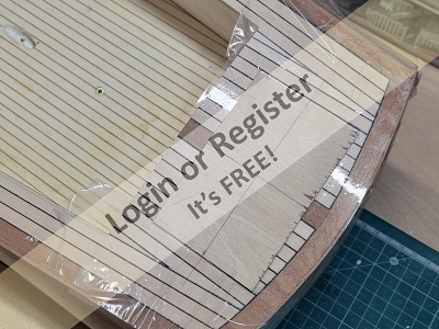
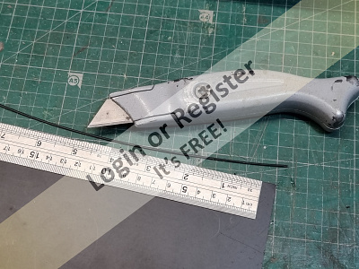
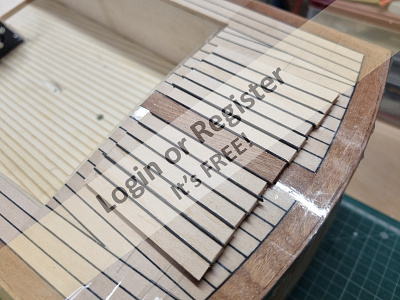
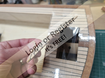
Made the bilge keels from two laminations of mahogany sheet to get the correct thickness and then glued them in place. Once this was done I was able to return to the superstructure. Drilled the holes for the portholes and then glued the cabin sides in position.
Made the forward cabin front window and glued in followed by that for the rear cabin. Bolted and screwed the upper support for the drop keel whilst I still had easy access.
Really starting to take shape now but still a long way to go!
Chris
🇬🇧 ChrisF
13 days ago


6 Posts
4 Followers
19 Likes
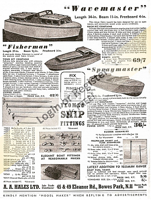
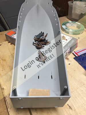
Wave master boat
This is a classic wave master it was built in the fifty's a nd a internet buy I have stripped out the rc engine and its tanks now on the research stage there are a few issues rear end smack thats had a poor repair done and the spray rails do not fit well of its history I know nothing
🇬🇧 Stephen T

14 days ago

1 Post
1 Follower
4 Likes
Vosper
Well, I'm about to start my Vosper. I painted the crew, glued the transom in place. made a rudder up because I'm just thinking about how I'll propel the boat, rummage around in the drawers for a motor and drive shaft prop that may take a while. The model is about 24 inches in length, and the third photo shows that it takes 7 screws to hold it to the hull easily, but it may be a problem changing batteries. Lots of thinking will be needed to R/C the Vosper.P/S Ron gave me some ideas so thanks, Ron.
🇨🇦 GARTH
15 days ago
|
|

Media Gallery
Fishing Trawler build
10 days ago by lukeH
Christmas theme
2 months ago by GARTH
SSMBC (Florida) meet: 12/7/2025 military focus
2 months ago by LewZ
SSMBC (Seminole, Florida) meet, Nov 16, 2025
2 months ago by LewZ
SSMBC (Seminole, Florida) meet, Nov. 2, 2025
3 months ago by LewZ
Spooky - (Evening sail November)
3 months ago by philcaretaker
Gaff Rigged Bristol Pilot Cutter Autumn / Fall
3 months ago by philcaretaker
Only 2 days left
3 months ago by GARTH
Professional Photographer at Southport
3 months ago by SouthportPat
Filming over water
4 months ago by philcaretaker
"Sailor Sam" greets onlookers at the Sunday morning "Run In The Park".
4 months ago by philcaretaker
Light up the Night on the September 25th 2025 including safety cautions
4 months ago by GARTH
|
|

Login To
Remove Ads
Remove Ads
Boat Clubs & Lakes
Recent Updates In Places

|
Black Mountain Radio Sailing Club
11 days ago by 🇺🇸 oefranz (
Able Seaman) |
|
|
Buxton Model Boat Club
2 months ago by 🇬🇧 philcaretaker (
Commodore) |
|
|
Schiffsmodellclub Sömmerda/OT leubingen
2 months ago by 🇨🇭 Mike Stoney (
Rear Admiral) |
|
|
Southport Model Boat Club
3 months ago by 🇬🇧 SouthportPat (
Commodore) |
|
|
BUXTON MODEL BOAT CLUB
3 months ago by 🇬🇧 philcaretaker (
Commodore) |
|
|

Upcoming Events

|
Jan
23 2026
|
Jan
25 2026
|
Edina Model Yacht Club at the Minneapolis Boat Show
Ended 2 hours ago
|
|
|

Boat Harbour
3 Photos
11 Likes
Sterling Century Seamaid
I got this model from a fellow Cofederation modeller member. The Model boat needed a few things, like a battery box area and a steering wheel that I'm still working on installing, plus a few other small things. I always like to have a driver, so I'll use my Dail Ernhart junior figure that I had in my duel cockpit runabout . The model was a wooden Sterling model kit that was well-made by that member. found the kit on Google images
🇨🇦 GARTH
9 days ago
12 Attributes
3 Comments
7 Photos
4 Likes
LESRO SPRITE
Not sure what the run time will be with the new brushless set-up, so I've put 15mins as a start point; I know I can get 10-12+ mins with this size motor and a 3200mAh 4s Lipo in a 63ins span KK Super Sixty trainer plane revving an11x4" prop alot higher, so driving a 35mm prop in water at a range of speeds should get over 15 mins ( I hope...).
Same with the speed - I'll let you judge from the video, but it's difficult to tell how fast she can go in such a small area.
As for current draw - no idea at this stage, but I'll try and do an amp test in the future.
The photos on open water are with the original brushed motor set up. I've also included comparative photos of original motor set-up and the brushless set up. The short video should speak for itself, it's the same one as in the Classic Model Power Boats thread.
Best regards,
Nick
🇳🇿 Nick Ward
12 days ago
11 Attributes
3 Comments
0 Photos
4 Likes
Non-Classic Fairey Builds
These come from the era of classic boats, including the 1960s and 70s and were timber hulled. The Fisherman 27 could be called a classic as it was a popular boat but I'm talking here in the context of models. I don't know of any of these being built and there certainly weren't any drawings or kits produced unlike with the classics like the Huntsman 31 etc.
These builds were borne out of my desire to build something different but still Faireys and were inspired by photographs found in books, which in the case of the River Cruiser, a small B&W photograph being my only source of information though with the hull being based on the Huntress made things easier.
🇬🇧 ChrisF
19 days ago
0 Attributes
14 Comments
0 Photos
6 Likes
Other Classic Fairey Builds
In addition to the Huntress I'm building all the other classic Faireys at the same scale of 1:12. None of them are finished yet!
The first of these was the Huntsman 28, followed by the Swordsman 33 (raised aft cabin version) and the Huntsman 31 aft cabin version - this started off as the full rear cockpit version called the Sport which was primarily intended for off-shore powerboat racing, but as I'd sold off my big 47" aft cabin version and my number of rear cockpit versions was increasing I decided to convert it to the aft cabin version mid-build.
Chris
🇬🇧 ChrisF
19 days ago
0 Attributes
13 Comments
5 Photos
9 Likes
Fairey Huntresses
I mainly scratch build my own models but when Dave Milbourn offered me one of the prototypes he'd built for testing the drawings for his scale 1:12 model it was too good to miss. This then set me on the course to build all my models to the same scale.
This included a Huntress Long Cabin version which features a stern-drive. Whilst wanting to build the classic well known Faireys I like to build some of their less well known ones as well.
Dave sadly passed away but I was then given the opportunity to obtain the second prototype which was even more detailed.
🇬🇧 ChrisF
20 days ago
0 Attributes
11 Comments
3 Photos
12 Likes
GLYNN GUEST KNOCKER WHITE TUG
NB some of the stats above such as run time, max amps, speed, are estimated. The actual finished weight was 727grams,.
This boat was recently finished and maidened on Christmas day on our new back yard pond. Since then I have added some LED navigation lights and cabin lighting. I'm very pleased with the result and would thoroughly recommend Glynn Guests designs for small pond models. They are simple and relatively cheap to build, yet with a little effort can emerge with plenty of character.
Due to the success of this one, I intend to build a couple more of his small designs, as well as a couple of Hal Harrisons, so watch this space.
Full details of this build are on this website in the build blog section.
rgds,
Nick Ward
🇳🇿 Nick Ward
27 days ago
12 Attributes
5 Comments
11 Photos
10 Likes
Re: R.A.F Crash Tender
This is a reduced model down to 28" from the 34" Crash Tender.
I then built it out of balsa wood and covere the bottom balsa skin with 1/16th ply.
I will get around to finishing it one day. Only part painted up to now.
The propellor on it in the picture is not the one that it will be run on it will have
a 25mm 3 bladed brass one on it. But I do also have a 20mm as a back up incase thats too big.
🇬🇧 BOATSHED
1 month ago
6 Attributes
2 Comments
1 Photo
9 Likes
Fire Crash Tender
Original Aerokits 46’’
850 motor
🇬🇧 Heners2332
1 month ago
6 Attributes
18 Comments
2 Photos
5 Likes
Fairmount Alpine
Purchased Built
🇬🇧 Heners2332
1 month ago
6 Attributes
3 Comments
|
|
How-To Articles
Electric Boat Engine Etc Etc
Revised 2 months ago
By Guy O
Essential or useful tools and utensils for the ship modeler. A final appendix lists the most common
Revised 3 months ago
By AlessandroSPQR
stop email notifications
Revised 3 months ago
By Ace23
painting epoxy over Humbrol and varnish enamels
Revised 5 months ago
By roycv
Cardan joint, Homokinetic joint, universal joint. Problems related to the junction between the engin
Revised 7 months ago
By AlessandroSPQR
various electrical connection diagrams for two motors
Revised 9 months ago
By tomarack
Lifeboats or work boats?
Revised 12 months ago
By AlessandroSPQR
Permanent magnet brushed electric motors. Main features. Basic elements of distinction. How to evalu
Revised 12 months ago
By AlessandroSPQR
When wooden planking the sides of hulls What Glues are you using?
Revised 1 year ago
By bruce1946
Fibreglassing a wooden hull
Revised 1 year ago
By DuncanP
|
|

Login To
Remove Ads
Remove Ads
Model Boats Website
This is the alert text. You can customize this text to be as long or short as needed. The modal height will adjust accordingly.
🛍️ Basket
Go AD FREE & get your membership medal
BRONZE
Less Ads
SILVER
GOLD
Ad Free
Cancel
Anytime
Anytime
£2.50
£4.50
£6.50
Subscribe
Main menu transported here on mobile
Login
Create New Account
Trending Topics
Members Online
Blog
Re: The tub test
jumpugly
30 minutes ago
Forum
Peterd has passed away quietly this evening
Ronald
2 hours ago
Blog
Re: Making the Rear Hatch
chugalone100
10 hours ago
Event
Edina Model Yacht Club at the Minneapolis Boat Show
chugalone100
12 hours ago
Forum
Identify model
Mike Stoney
12 hours ago
Forum
Question of the Day?
PhilH
16 hours ago
Blog
New Moth MKII semi scale yacht
jbkiwi
18 hours ago
Forum
Meet Selma from Norway 🇳🇴
jumpugly
2 days ago
Blog
Re: Vosper
Ronald
2 days ago
Forum
Adhesives
bruce1946
2 days ago
Forum
Sailing at the Toronto Boat Show
ScouterChil
2 days ago
Blog
Last gasp before maiden splash in warm weather
Chum444
3 days ago
Forum
How much is too much? (If it ain't free and I need to volunteer then I ain't joining.)
hermank
3 days ago
Forum
motor for large paddle steamer. Advice required
Hermione
4 days ago
Blog
Re: Fairey Fisherman 27
zooma
4 days ago
Blog
Re: Fairey Fisherman 27
zooma
4 days ago
Forum
Interesting sail on this Catboat
luckyduck
4 days ago
Blog
Re: LISA M Motor Yacht
DuncanP
5 days ago
Forum
4 vessels for sale
Rogal118
5 days ago
Forum
Mary Ann 472
Ronald
6 days ago
Blog
Re: She’s done
DWBrinkman
6 days ago
Blog
Re: VIC SMEED'S VIVACITY
jumpugly
6 days ago
Forum
Sprite
zooma
6 days ago
Blog
Re: Construction report "Pilot Cutter Britannia" 1 : 24
Mike Stoney
7 days ago
Harbour
Re: Sterling Century Seamaid
jumpugly
8 days ago
Forum
VIC SMEED'S VIVACITY
Nick Ward
8 days ago
Gallery
Re: Fishing Trawler build
Mike Stoney
8 days ago
Forum
Speedline models RNLI 1/16 Shannon.
lukeH
8 days ago
LewZ
Vice Admiral
7,307 Points
23 seconds ago
stevedownunder
Commodore
4,242 Points
35 seconds ago
BOATSHED
Commander
2,872 Points
51 seconds ago
Harwind
Leading Seaman
87 Points
1 minute ago
melian
Recruit
0 Points
2 minutes ago
roycv
Fleet Admiral
10,327 Points
11 minutes ago
chugalone100
Lieutenant Commander
2,465 Points
27 minutes ago
Steves-s
Chief Petty Officer 1st Class
499 Points
28 minutes ago

jumpugly
Admiral
8,693 Points
29 minutes ago
RNinMunich
Fleet Admiral
40,180 Points
41 minutes ago
Ronald
Fleet Admiral
13,165 Points
49 minutes ago
Lauriem
Petty Officer 1st Class
241 Points
53 minutes ago

SouthportPat
Commodore
4,818 Points
59 minutes ago
RossM
Captain
3,224 Points
1 hour ago
ekoral
Master Seaman
137 Points
1 hour ago
neilw
Lieutenant Commander
2,364 Points
2 hours ago
RonH
Warrant Officer
806 Points
2 hours ago
GARTH
Commodore
4,035 Points
2 hours ago
MarkS3
Recruit
0 Points
2 hours ago
Rowen
Captain
3,547 Points
2 hours ago
AlessandroSPQR
Fleet Admiral
12,538 Points
2 hours ago
GaryLC
Captain
3,600 Points
3 hours ago
Andreas
Recruit
0 Points
3 hours ago
DavidT4
Recruit
5 Points
3 hours ago
ChrisF
Rear Admiral
5,958 Points
3 hours ago
Chum444
Commodore
4,105 Points
3 hours ago
Rookysailor
Commodore
4,986 Points
4 hours ago
zooma
Vice Admiral
6,537 Points
4 hours ago
DWBrinkman
Commodore
4,455 Points
4 hours ago
Mike Stoney
Rear Admiral
5,350 Points
5 hours ago
PhilH
Lieutenant
1,979 Points
5 hours ago
Capt Bob
Recruit
0 Points
6 hours ago
NeilP1
Recruit
0 Points
6 hours ago
stuartbell3553
Recruit
12 Points
7 hours ago
premecekcz
Master Seaman
123 Points
7 hours ago
IanH5
Recruit
0 Points
7 hours ago
Hsailer
Able Seaman
42 Points
7 hours ago
Wolle
Commodore
4,944 Points
7 hours ago
Missouri
Master Seaman
133 Points
7 hours ago
powell39
Recruit
0 Points
7 hours ago
RubaDub
Petty Officer 1st Class
245 Points
7 hours ago
dash8man
Able Seaman
33 Points
8 hours ago
JOHN
Midshipman
1,157 Points
8 hours ago

Gaggs
Recruit
0 Points
8 hours ago
eddyc
Recruit
6 Points
9 hours ago
Jay
Recruit
15 Points
9 hours ago
luckyduck
Lieutenant
1,903 Points
9 hours ago
pressonreguardless
Rear Admiral
5,315 Points
10 hours ago
hermank
Rear Admiral
5,393 Points
10 hours ago
hercule
Recruit
0 Points
10 hours ago
Login To
Remove Ads
Remove Ads
🏠
Home
Home
📰
Trending
Trending
💬
Forum
Forum
🗝
Login / Join
Login / Join
|
Cookies are used for ads personalisation.
By using this website you agree to our use of cookies. More Info |
Main Menu
🚤 Model Boats
• Forum
• Build Blogs
• Media Gallery
• Boat Clubs & Lakes
• Events
• Boat Harbour
• How-To Articles
• Useful Links
• The Games Chest
This Website
🔍 Search
📝 Guestbook
👨👩👧👦 Members (1,789)
📣 Support
Hobby Supplies
🛍️ Online Shop
Login
🗝 Login
🗝 Create New Account
▼
Media Gallery
X
1 of 4
► |
◄ |
Media Viewer
^
_
X
Share
X
Flag Inappropriate Post
X
| Select Reason | |
| Sexual content Includes graphic sexual activity, nudity, and other sexual content. | |
| Violent or repulsive content Violent or graphic content, or content posted to shock viewers. | |
| Hateful or abusive content Content that promotes hatred against protected groups, abuses vulnerable individuals, or engages in cyberbullying. | |
| Harmful dangerous acts Content that includes acts that may result in physical harm. | |
| Child abuse Content that includes sexual, predatory or abusive communications towards minors. | |
| Promotes terrorism Content intended to recruit for terrorist organisations, incite violence, glorify terrorist attacks, or otherwise promote acts of terrorism. | |
| Spam or misleading Content that is massively posted or otherwise misleading in nature. | |
| Infringes my rights Privacy, copyright and other legal complaints. | |
Basket Updated
X
Loading...
Loading
Loading Uploader...