Join Us On Social Media!

|

|

|
Download The App!
Login To
Remove Ads
Remove Ads
Login To
Remove Ads
Remove Ads
Model Boats Website
 Fleet Admiral)

 Liked Graupner mc-26 5 years ago
 Liked Graupner mc-26 5 years ago


United Kingdom

Recent Posts
📝 stepper motors
5 years ago by 🇬🇧 G6SWJ ( Sub-Lieutenant)
Sub-Lieutenant)✧ 24 Views · 5 Likes
Flag
📝 Reply
The jumble of wires that you can often see are akin to an ESC
This video is interesting as it shows the slow & smooth movement as well as significant rpm
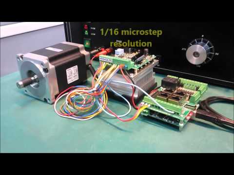
This video is interesting as it shows the slow & smooth movement as well as significant rpm
▲
⟩⟩
RNinMunich
MouldBuilder
Martin555
Colin H
redpmg
Login To
Remove Ads
Remove Ads
📝 stepper motors
5 years ago by 🇬🇧 G6SWJ ( Sub-Lieutenant)
Sub-Lieutenant)✧ 24 Views · 3 Likes
Flag
📝 Reply
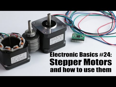
A few YouTube links to while away some time...


▲
⟩⟩
MouldBuilder
Martin555
redpmg
📝 stepper motors
5 years ago by 🇬🇧 G6SWJ ( Sub-Lieutenant)
Sub-Lieutenant)✧ 28 Views · 3 Likes
Flag
📝 Reply
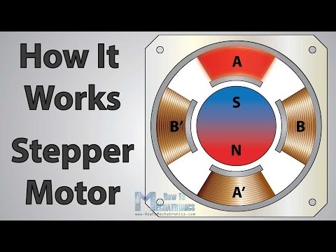
What an interesting thought - you may be onto something - essentially they are just brushless motors.
Some of them have significant torque - you have got me think now as I am looking for 2 motors for my 8ft HMS Hermes...cogs are turning in my head....
Let me mull that over and I will come back to you with a considered response rather than shooting from the hip....
Regards
Jonathan
Some of them have significant torque - you have got me think now as I am looking for 2 motors for my 8ft HMS Hermes...cogs are turning in my head....
Let me mull that over and I will come back to you with a considered response rather than shooting from the hip....
Regards
Jonathan
▲
⟩⟩
MouldBuilder
Martin555
redpmg
📝 stepper motors
5 years ago by 🇬🇧 G6SWJ ( Sub-Lieutenant)
Sub-Lieutenant)✧ 38 Views · 2 Likes
Flag
📝 Reply
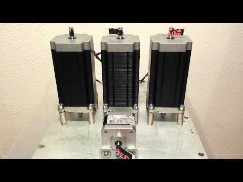
Could not find these earlier... hopefully self explanatory
▲
⟩⟩
alan44
T33CNO
📝 stepper motors
5 years ago by 🇬🇧 G6SWJ ( Sub-Lieutenant)
Sub-Lieutenant)✧ 34 Views · 4 Likes
Flag
📝 Reply
Hi Martin,
This will be used on HMS Rodney
This will be used on HMS Rodney
▲
⟩⟩
jbkiwi
MouldBuilder
Martin555
T33CNO
📝 stepper motors
5 years ago by 🇬🇧 G6SWJ ( Sub-Lieutenant)
Sub-Lieutenant)✧ 36 Views · 4 Likes
Flag
📝 Reply
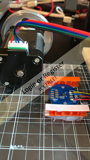
I have been playing with stepper motors for quite a few years. Biggest issue is always that unlike a servo they have no feedback mechanism for where they are "pointing".
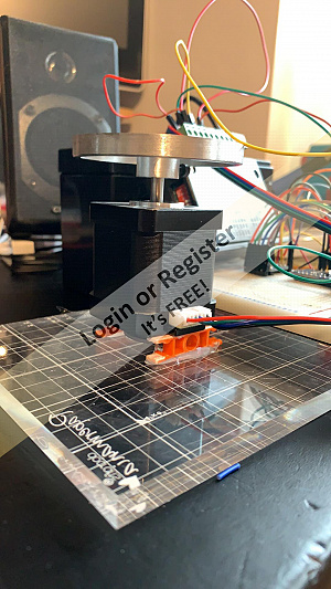
I found a sensor that uses a diametrically magnetised magnet - I have attached the magnet to the botton of the stepper shaft.
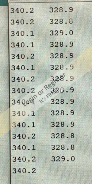
I wrote a quick program to make the stepper move 200 steps - report it's position via the sensor and then move 200 steps the other way and report it's position - the stepper just sweeps between the 2 positions and the sensor reports the "magnet angle" before the stepper commences moving in the opposite direction.
Blown away with a 0.25 degree accuracy so far - the sensor can be calibrated - the kit to achieve this arrived today in the post....
Regards
Jonathan
I found a sensor that uses a diametrically magnetised magnet - I have attached the magnet to the botton of the stepper shaft.
I wrote a quick program to make the stepper move 200 steps - report it's position via the sensor and then move 200 steps the other way and report it's position - the stepper just sweeps between the 2 positions and the sensor reports the "magnet angle" before the stepper commences moving in the opposite direction.
Blown away with a 0.25 degree accuracy so far - the sensor can be calibrated - the kit to achieve this arrived today in the post....
Regards
Jonathan
▲
⟩⟩
MouldBuilder
T33CNO
Martin555
Colin H
📝 Fun with digital sound
5 years ago by 🇬🇧 G6SWJ ( Sub-Lieutenant)
Sub-Lieutenant)✧ 34 Views · 4 Likes
Flag
📝 Reply
Having had to focus on paying the bills more so less time to play and post on the forum for the last many months....
I have found some time to mess around with some proportional sound production - this is work in progress but this is where I have got to...
I have found some time to mess around with some proportional sound production - this is work in progress but this is where I have got to...

▲
⟩⟩
RNinMunich
jbkiwi
Martin555
Colin H
📝 Graupner mc-26
5 years ago by 🇬🇧 G6SWJ ( Sub-Lieutenant)
Sub-Lieutenant)✧ 90 Views · 2 Likes
Flag
📝 Reply
Hi Len,
I feel your frustration. I will digest what you have posted so I can come back upto speed with the latest info.
Did you find Krick customer support responsive?
Regards
Jonathan _._
I feel your frustration. I will digest what you have posted so I can come back upto speed with the latest info.
Did you find Krick customer support responsive?
Regards
Jonathan _._
▲
⟩⟩
bombero
Martin555
📝 Graupner mc-26
5 years ago by 🇬🇧 G6SWJ ( Sub-Lieutenant)
Sub-Lieutenant)✧ 82 Views · 1 Like
Flag
📝 Reply
Hi Len,
Will read through and respond later.
Suggest mini steps - for now forget external power supply - stick with receiver battery whilst getting used to programming radio.
So pick your channel and then use the centre pin as the positive rail and either of the 2 outer pins as the negative and then see if they come live (using multimeter) when switched - of course there is the minor issue of programming the radio
Logical way forward?
Jonathan_._
▲
⟩⟩
Martin555
📝 openTX and openLRSng
5 years ago by 🇬🇧 G6SWJ ( Sub-Lieutenant)
Sub-Lieutenant)✧ 18 Views · 1 Like
Flag
📝 Reply
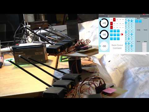
Early days but my version of openLRS - one that will be easy to understand and use!!!
16CH RC UHF with telemetry being streamed back from model
A quick test of latency - pretty good considering convaluted path for the RC commands...
Jonathan _._
16CH RC UHF with telemetry being streamed back from model
A quick test of latency - pretty good considering convaluted path for the RC commands...
Jonathan _._
▲
⟩⟩
Martin555
📝 Graupner mc-26
5 years ago by 🇬🇧 G6SWJ ( Sub-Lieutenant)
Sub-Lieutenant)✧ 77 Views · 1 Like
Flag
📝 Reply
Len,
Attached is a better instuction PDF - more subtle detail I think
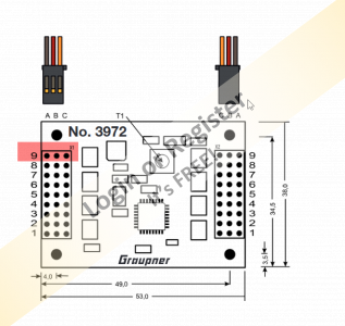
My understanding is that the centre B pin on both columns X1 and X2 pin 1-8 is always unswitched positive (live) - it's the hard wired to the power line supplied via the receiver patch cable - you could validate this with a meter.
Indeed I would progress using your multi meter (inputs) as the device you wish to switch on and off to test things out and not blow anything else
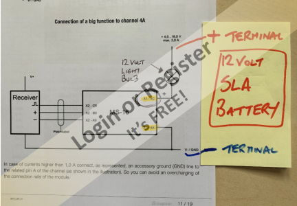
For a small circuit (low current) you would be using the RX battery supply directly (no choice)
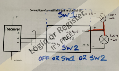
You would connect the device you want to switch (bulb/small motor) directly to the 3972 pin B + power and then either pin A or C to pick up a switched negative line
Note you can have 2 circuits per channel as 2 switched negative lines (A&C)
If you choose to use an external power supply (not the RX battery) then you DO NOT connect the positive line of the external supply to the 3972
To use an external power supply:
Connect the negative external power to pin A
Connect the device negative connection to pin C
Connect the positive from the external power supply directly to the device (NOT the 3972)
*** When using an external power supply, you have used pin A and C so you can only switch one device per channel
Please senser check this for accuracy and that my understaning is correct
I would progress with only one item plugged into the 3972!!
And the came the software configuration 😊
Regards
Jonathan _._

Attached is a better instuction PDF - more subtle detail I think
My understanding is that the centre B pin on both columns X1 and X2 pin 1-8 is always unswitched positive (live) - it's the hard wired to the power line supplied via the receiver patch cable - you could validate this with a meter.
Indeed I would progress using your multi meter (inputs) as the device you wish to switch on and off to test things out and not blow anything else
For a small circuit (low current) you would be using the RX battery supply directly (no choice)
You would connect the device you want to switch (bulb/small motor) directly to the 3972 pin B + power and then either pin A or C to pick up a switched negative line
Note you can have 2 circuits per channel as 2 switched negative lines (A&C)
If you choose to use an external power supply (not the RX battery) then you DO NOT connect the positive line of the external supply to the 3972
To use an external power supply:
Connect the negative external power to pin A
Connect the device negative connection to pin C
Connect the positive from the external power supply directly to the device (NOT the 3972)
*** When using an external power supply, you have used pin A and C so you can only switch one device per channel
Please senser check this for accuracy and that my understaning is correct
I would progress with only one item plugged into the 3972!!
And the came the software configuration 😊
Regards
Jonathan _._
▲
⟩⟩
Martin555
Login To
Remove Ads
Remove Ads
📝 Graupner mc-26
5 years ago by 🇬🇧 G6SWJ ( Sub-Lieutenant)
Sub-Lieutenant)✧ 75 Views · 1 Like
Flag
📝 Reply
ToraDog,
Not at all - any info adds to the understanding. I played with the Robbe system a few years back and unfortunately my memory is not what it once was....
I now remember that the centre pin on the switch units is normally "unswitched positive" and live all the time whilst connected to a power supply.
The 2 outer pins are switched ground allowing/facilitating 2 switch circuits per channel
ToraDog - is that your understanding?
Still can't remember how you serve different voltages to different channels - indeed it's not obvious how you connect any battery directly to the Graupner unit as unlike the Robbe version their is no "battery" connection identified - the unit itself being powered I presume from the receiver patch lead....
Regards
Jonathan _._
▲
⟩⟩
Martin555
📝 Graupner mc-26
5 years ago by 🇬🇧 G6SWJ ( Sub-Lieutenant)
Sub-Lieutenant)✧ 74 Views · 1 Like
Flag
📝 Reply
Hi Len,
Coming back to the subject afresh I decided to re-read the instructions before looking at your update.
Page 10 states "The module consumes so few current that you can connect it through the included patch cable directly to the multichannel output of the receiver"
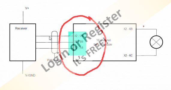
Page 11 - the picture clearly shows the patch cable between the receiver and 16ch 3972 connected to slot X2 A9 B9 C9 (left hand column of pins labelled FS_Impuls)
I think we agree on the above?
Do you have a multi meter?
I would suggest that you don't plug anything into the multi switch right now and try to follow my thoughts...
I will try to validate my suggestion this weekend with the kit I have
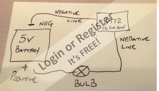
This (3972)is a switch. It is a single pole switch so can only switch one line either positive or negative but not both. We are told that it switches the negative/ground line
So this would mean for each channel we make only 2 connections to the switch for each channel (an in and an out for want of better terminology)
This would mean that we insert the switch into the negative/ground line only (see attached image)
Pic to follow shortly
I did not understand your post 100% but hopefully my post may add to the joint understanding
Update - see later post which over-rides some of this text
Regards
Jonathan
Coming back to the subject afresh I decided to re-read the instructions before looking at your update.
Page 10 states "The module consumes so few current that you can connect it through the included patch cable directly to the multichannel output of the receiver"
Page 11 - the picture clearly shows the patch cable between the receiver and 16ch 3972 connected to slot X2 A9 B9 C9 (left hand column of pins labelled FS_Impuls)
I think we agree on the above?
Do you have a multi meter?
I would suggest that you don't plug anything into the multi switch right now and try to follow my thoughts...
I will try to validate my suggestion this weekend with the kit I have
This (3972)is a switch. It is a single pole switch so can only switch one line either positive or negative but not both. We are told that it switches the negative/ground line
So this would mean for each channel we make only 2 connections to the switch for each channel (an in and an out for want of better terminology)
This would mean that we insert the switch into the negative/ground line only (see attached image)
Pic to follow shortly
I did not understand your post 100% but hopefully my post may add to the joint understanding
Update - see later post which over-rides some of this text
Regards
Jonathan
▲
⟩⟩
Martin555
📝 Graupner mc-26
5 years ago by 🇬🇧 G6SWJ ( Sub-Lieutenant)
Sub-Lieutenant)✧ 72 Views · 1 Like
Flag
📝 Reply
Hi Len,
Spinning plates right now ( well if I am honest doing the house work! )- will have a look later and digest/comment on your findings
Pleased you are sticking with it - regardless of the frustration to date!
Regards
Jonathan
Spinning plates right now ( well if I am honest doing the house work! )- will have a look later and digest/comment on your findings
Pleased you are sticking with it - regardless of the frustration to date!
Regards
Jonathan
▲
⟩⟩
Martin555
📝 Graupner mc-26
6 years ago by 🇬🇧 G6SWJ ( Sub-Lieutenant)
Sub-Lieutenant)✧ 64 Views · 1 Like
Flag
📝 Reply
Hi Len,
It appears that this has nothing to do with any software setting.
It looks like a hardware/cabling issue (sure you had deteremined this already!)
I think for now to resolve the hardware issue it's a case for Krick customer support
In the instructions for the "ploarity reversing" unit - it refers to "memory setting" which must be disabled.
The relates back to terminology on the Robbe mutli switch - the term "memory" can be substitued with "latching". In other words the Multi switch output into the Krick polarity reversing unit must not be latching but temporary switched (i.e It's only on whilst you are holding a non latching switch in the on position)...
Hope you get some good news from Krick HQ
Regards
Jonathan _._
▲
⟩⟩
Martin555
📝 Graupner mc-26
6 years ago by 🇬🇧 G6SWJ ( Sub-Lieutenant)
Sub-Lieutenant)✧ 62 Views · 1 Like
Flag
📝 Reply
Len,
Re-reading the documentation it looks like the "patch cable" between the receiver and the multi switch unit should be plugged into X2 Slot 9 - top slot on the RHS column labelled FS-Impuls
Please check and confirm this for yourself .....
I would suggest that you only have one thing plugged into the multi switch at a time whilst working through these issues - perhaps the blue light would be a good option?
Crazy that X1 and X2 are not marked on the multi switch case
Update - I see from your hand written notes that you have used X2 slot 9 - is that correct..
Regards
Jonathan _._
▲
⟩⟩
Martin555
📝 Graupner mc-26
6 years ago by 🇬🇧 G6SWJ ( Sub-Lieutenant)
Sub-Lieutenant)✧ 56 Views · 1 Like
Flag
📝 Reply
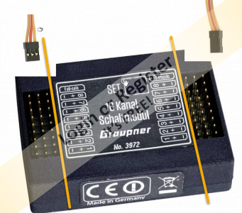
Len one think to note on the Graupner No.3972 multi switch unit is that for both columns of pins the outer pin closest to the edge of the case is the negative pin.
So the plugs one one side will be the reverse orientation of the other side
Another way of looking at it it the orange lead should always be closest to the centre of the unit for both columns
I can see that there are no orientation guide like there are on some receivers so you can plug a lead in either way!!
Jonathan _._
▲
⟩⟩
Martin555
📝 Graupner mc-26
6 years ago by 🇬🇧 G6SWJ ( Sub-Lieutenant)
Sub-Lieutenant)✧ 56 Views · 1 Like
Flag
📝 Reply
Hello Len,
Was it a Krick No.8249 you cooked?
If so where was it plugged into when the blue smoke got released?
Is it possible to post a pic of how(plug orientation) and where it was plugged in (power off of course) - and are the plugs shaped so they only plug in one way?
Do you have a relay unit which is intended for use with the pump?
PS now up to speed with the wiring diagram.
Will suggest the way forward once answers to questions above....
Regards
Jonathan
▲
⟩⟩
Martin555
📝 Graupner mc-26
6 years ago by 🇬🇧 G6SWJ ( Sub-Lieutenant)
Sub-Lieutenant)✧ 54 Views · 2 Likes
Flag
📝 Reply
Let me get my head around the detail and I will come back to you.
Sure there is a way forward - hold the faith!
Regards
Jonathan _._
Sure there is a way forward - hold the faith!
Regards
Jonathan _._
▲
⟩⟩
RNinMunich
Martin555
📝 Graupner mc-26
6 years ago by 🇬🇧 G6SWJ ( Sub-Lieutenant)
Sub-Lieutenant)✧ 55 Views · 2 Likes
Flag
📝 Reply
Len,
Before you jump ship - it would be worth taking a step back.
You could find yourself in a worse position($$$) and still not having your desired outcome!!
Getting 16 channels of RC to your model is relatively easy - it's what you do with them once they exit the receiver that's key - specifcally what hardware does the receiver interface with.
This is where the Graupner Nautic multi switch unit scores big time compared to other solutions.
Map out what you need to control on the model and what type of control it needs (proportional stick or slider, switch on / off - momentary or latched).
We may be able to suggest a way forward once we understand your requirements...
Look forward to your update
Regards
Jonathan _._
▲
⟩⟩
ToraDog
Martin555
📝 Graupner mc-26
6 years ago by 🇬🇧 G6SWJ ( Sub-Lieutenant)
Sub-Lieutenant)✧ 54 Views · 3 Likes
Flag
📝 Reply
Hi Len,
My catch phrase is "I've learnt most of my stuff by getting very stuck first"
I am currently working on a project that I had working a few years back - I am about 4 hours in and it's still not working - if I had written a note or two at the time .....
The most annoying aspect is I know what is wrong - I just can't get it to work.
The Graupner radio is a great piece of kit - it's just complex to get up and running.
If you really want to jump ship then the FrSky Taranis is a sure bet.
Happy to work with you to get the MC26 working...
If you map out what you need to control and with what (proportional, on/off) etc perhaps we can get this working.
I have got myself stuck with "tech" so many times - I am just very stubborn and will not be beaten - this can often lead to some long journeys...
Regards
Jonathan _._
▲
⟩⟩
Martin555
RNinMunich
ToraDog
Login To
Remove Ads
Remove Ads
📝 Graupner mc-26
6 years ago by 🇬🇧 G6SWJ ( Sub-Lieutenant)
Sub-Lieutenant)✧ 53 Views · 1 Like
Flag
📝 Reply
Hi Len,
"Am I missing something" - yes sort of but I would suggest that most users would be in the same boat (excuse the pun) 😊
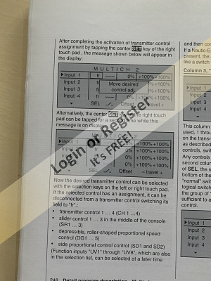
When you go into the "Control Switch" screen it is expecting you to "move a desired control" - e.g. A CONTROL like a stick etc in fact anything apart from a SWITCH from the 2 banks of 12 switches
It is really obvious NOT
I have 2 Jeti radio's that are equally capable/complex - they are a breeze to use and program. The Taranis radio is also a very capable radio and relatively easy to use.
The Graupner radio I would suggest is a little cumbersome - this would not be a problem so much if the manual was user friendly
Regards
Jonathan _._
"Am I missing something" - yes sort of but I would suggest that most users would be in the same boat (excuse the pun) 😊
When you go into the "Control Switch" screen it is expecting you to "move a desired control" - e.g. A CONTROL like a stick etc in fact anything apart from a SWITCH from the 2 banks of 12 switches
It is really obvious NOT
I have 2 Jeti radio's that are equally capable/complex - they are a breeze to use and program. The Taranis radio is also a very capable radio and relatively easy to use.
The Graupner radio I would suggest is a little cumbersome - this would not be a problem so much if the manual was user friendly
Regards
Jonathan _._
▲
⟩⟩
Martin555
📝 openTX and openLRSng
6 years ago by 🇬🇧 G6SWJ ( Sub-Lieutenant)
Sub-Lieutenant)✧ 19 Views · 2 Likes
Flag
📝 Reply
Hi,
Anybody have experience/views on using openTX in conjunction with openLRSng?
I am insterested in opinions as to if it's reliable, easy to use....
Thank you in advance
Jonathan _._
OpenTX = open software that you can run on some radio handsets
Anybody have experience/views on using openTX in conjunction with openLRSng?
I am insterested in opinions as to if it's reliable, easy to use....
Thank you in advance
Jonathan _._
OpenTX = open software that you can run on some radio handsets


▲
⟩⟩
Ianh
Martin555
📝 Graupner mc-26
6 years ago by 🇬🇧 G6SWJ ( Sub-Lieutenant)
Sub-Lieutenant)✧ 52 Views · 1 Like
Flag
📝 Reply
Hi Bombero,
I think you will finds the MC26 & MC32 software are all but the same!
If the instructions have the same circuit diagram then it does not relate to the switch unit you have (No.3972) but the (No.4159).
If you look at the face of your mutli switch unit I think the "patch" cable will go in the top left connection marked "failsafe" or as highlighted in previous image X1 Slot 9
It is very likely that the multi 16 channel data is sent from the receiver (channel as configured 5 through 8) down the patch cable in 2 alternating blocks/frames of 8 channels each
You can test this all with the GR16 receiver - you don't need to wait for the GR32!!
Regards
Jonathan_._
▲
⟩⟩
Martin555
💬 Re: HMS York D98
6 years ago by 🇬🇧 G6SWJ ( Sub-Lieutenant)
Sub-Lieutenant)✧ 20 Views · 1 Like
Flag
💬 Add Comment
Hi Ron,
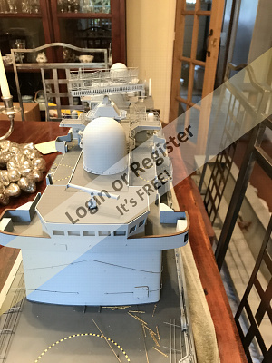
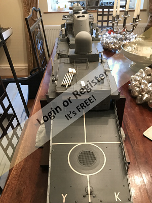
It's about 80% complete - lots of detailing,stanchions & railings to be fitted.
The model is built on a Fleetscale hull and "semi-kit" - the superstructure is scratch built...
It's about 80% complete - lots of detailing,stanchions & railings to be fitted.
The model is built on a Fleetscale hull and "semi-kit" - the superstructure is scratch built...

▲
⟩⟩
Martin555
💬 Re: HMS York D98
6 years ago by 🇬🇧 G6SWJ ( Sub-Lieutenant)
Sub-Lieutenant)✧ 22 Views · 3 Likes
Flag
💬 Add Comment
Colin
Not sure how Mischa (my female 6 year old springer) got on here - I'll leave her there as it makes me smile
Geoff L
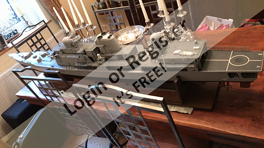
Much to my wifes dislike our dining room table is a often a temporary staging post for most arrivals and departures - not allowed to leave them there very long.
HMS York is now berthed safely in my den alongside HMS Chatham
Regards
Jonathan _._
Not sure how Mischa (my female 6 year old springer) got on here - I'll leave her there as it makes me smile
Geoff L
Much to my wifes dislike our dining room table is a often a temporary staging post for most arrivals and departures - not allowed to leave them there very long.
HMS York is now berthed safely in my den alongside HMS Chatham
Regards
Jonathan _._
▲
⟩⟩
Colin H
Ronald
Martin555
📝 Graupner mc-26
6 years ago by 🇬🇧 G6SWJ ( Sub-Lieutenant)
Sub-Lieutenant)✧ 50 Views · 1 Like
Flag
📝 Reply
Arghh!!!
How do you upload images in sequence - it seems to chew the names even if A.jpg,B.jpg etc
How do you upload images in sequence - it seems to chew the names even if A.jpg,B.jpg etc
▲
⟩⟩
Martin555
📝 Graupner mc-26
6 years ago by 🇬🇧 G6SWJ ( Sub-Lieutenant)
Sub-Lieutenant)✧ 52 Views · 4 Likes
Flag
📝 Reply
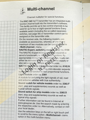
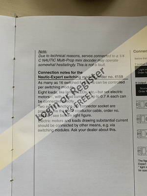
Having re-read the PDF manual online the instructions are shocking - I can only presume they used some auto translate software.
I have a programming manual for the MC32 - letter format about 1 inch thick!
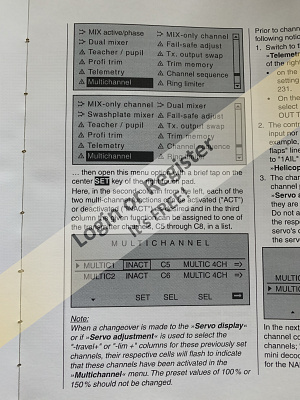
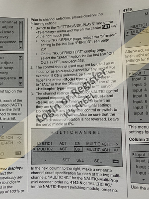
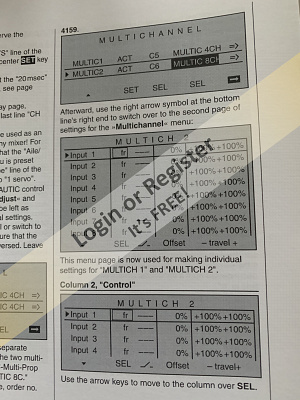
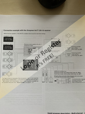
I have taken images of the "Multichannel" instuctions, clearly you will need to think of these in terms of MC26 offering but they might help fill some of the gaps especailly with regard to assigning control surfaces (Stick/switch/slider) and their travel limits
Sorry the PDF reads back to front - the last page comes first
Regards
Jonathan _._

I have a programming manual for the MC32 - letter format about 1 inch thick!
I have taken images of the "Multichannel" instuctions, clearly you will need to think of these in terms of MC26 offering but they might help fill some of the gaps especailly with regard to assigning control surfaces (Stick/switch/slider) and their travel limits
Sorry the PDF reads back to front - the last page comes first
Regards
Jonathan _._
▲
⟩⟩
MouldBuilder
Ianh
RNinMunich
Martin555
📝 HMS York D98
6 years ago by 🇬🇧 G6SWJ ( Sub-Lieutenant)
Sub-Lieutenant)✧ 19 Views · 4 Likes · 9 Comments
Flag
💬 Add Comment
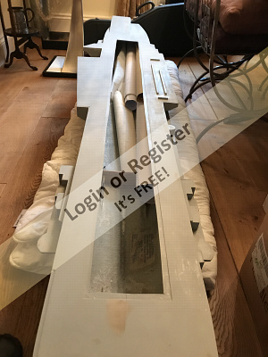
Just a few quick pics - just landed in my posession - needs to be completed


▲
⟩⟩
marky
Rookysailor
Martin555
Colin H
📝 Graupner mc-26
6 years ago by 🇬🇧 G6SWJ ( Sub-Lieutenant)
Sub-Lieutenant)✧ 51 Views · 3 Likes
Flag
📝 Reply
Hi - I have an MC32 - I don't use it much...
The MC26 is a later model and I believe will be a little different to how I descibe below but similar.
Basically you can expand 2 of the receiver output channels into multichannel outputs (4 or 8) and once configured in ther handset software plug a multi unit (switcher 4 or 8 channel two state on/off switch or 4 channel porportional )into those sockets
On the MC32 you have 2 "Multichannels" (MUTLIC1 & MULTIC2) that you can configure(point to) (C5,C6,C7 or C8) output on the receiver. You can further set each on these Multichannels to be either a 4 or 8 function multichannel
A Nautic switching unit for the MC32 may have the number '16' in it's name but it's an 8 channel switch to confuse things
So using one of the 2 Mutlichannel software configurations - (MULTIC1) in the handset software, set to say Channel 5 you would plug the Nautic Multiswitch "Empflanger" socket into the receiver channel slot 5
This means the modified (Multichannel data stream) output of receiver channel 5 now goes into the Nautic Switch and we can switch multiple circuits.
The mapping of exactly what physical stick/switch/slider or pot to each of the Multichannels is performed in the handset software
Reading between the lines a new variant of the Nautic 16 switch does allow you to switch 16 circuits. I believe it has 2 inputs (A&B) - these would I think be 2 x 8 channels inputs
So....
MULTIC1 8 channels - Mapped to Channel 5 - Plugged into Socket A
MULTIC2 8 channels - Mapped to Channel 6 - Plugged into Socket B
Would give you 16 switched channels.
Do you have 2 sockets on your switch unit marked A&B?
Update - not quite as explained - update to follow shortly!!
Here is a link for the multiswitch manual

▲
⟩⟩
Ianh
RNinMunich
Martin555
Login To
Remove Ads
Remove Ads