Join Us On Social Media!

|

|

|
Download The App!
Login To
Remove Ads
Remove Ads
Login To
Remove Ads
Remove Ads
Model Boats Website
 Fleet Admiral)
 Captain)
 Liked Emma C. Berry 10 months ago
 Liked 1:4 scale Clinker Dinghy 10 months ago
 Liked Skiff sailing 10 months ago
 Liked Re: Now in Color 10 months ago
 Liked Re: Bonehead Strikes Again! 10 months ago


United States


Recent Posts
💬 Re: Fin
7 hours ago by 🇺🇸 Jerry Todd ( Sub-Lieutenant)
Sub-Lieutenant)✧ 8 Views · 4 Likes
Flag
💬 Add Comment
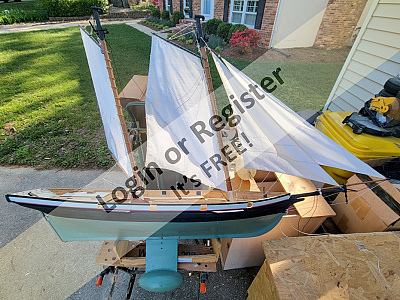
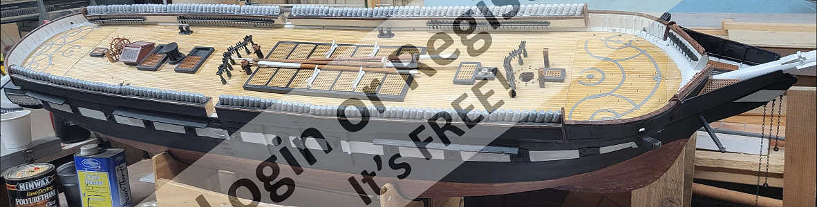
The sails were laid out with panel lines aligned to the run of the cloth. At the moment the heads'ls aren't attached to stays, but have a bit of cord attached at the head and tack to hang them up - ie, they're jury-rigged.


▲
⟩⟩
roycv
EdW
SimpleSailor
hermank
Login To
Remove Ads
Remove Ads
📝 Fin
2 days ago by 🇺🇸 Jerry Todd ( Sub-Lieutenant)
Sub-Lieutenant)✧ 19 Views · 5 Likes · 2 Comments
Flag
💬 Add Comment
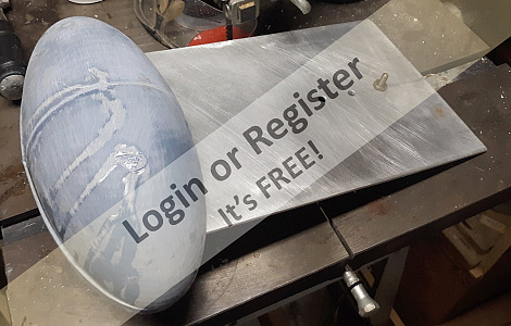
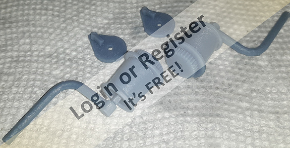
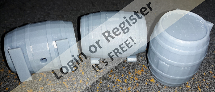
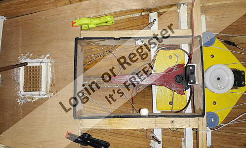
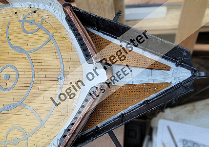
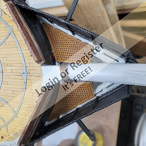
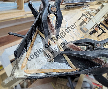
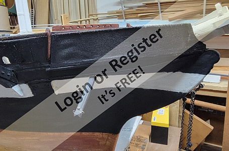
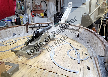
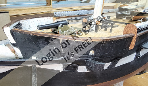
While trying to clean up the shop, I got Pride out of her corner, and put her fin in to get a picture
The holes in it are for depth adjustment, from 15" to 13". It weights 25 pounds, so it the primary ballast for the model, though a little will go inside to adjust how she sits in the water. Obviously it's removable, and without it, the models only weights about 20 pounds, even with the battery in.
The holes in it are for depth adjustment, from 15" to 13". It weights 25 pounds, so it the primary ballast for the model, though a little will go inside to adjust how she sits in the water. Obviously it's removable, and without it, the models only weights about 20 pounds, even with the battery in.
▲
⟩⟩
EdW
SimpleSailor
hermank
chugalone100
Ronald
📝 Brace Winch Concept
1 month ago by 🇺🇸 Jerry Todd ( Sub-Lieutenant)
Sub-Lieutenant)✧ 26 Views · 5 Likes · 1 Comment
Flag
💬 Add Comment
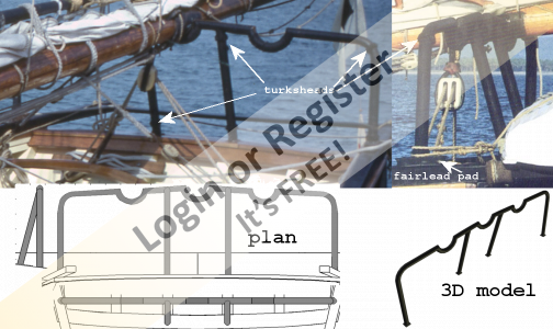
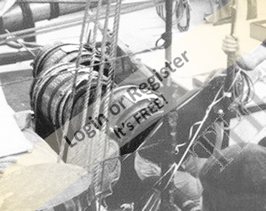
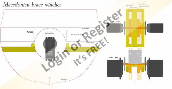
I'm building a web page on my site dealing with sail controls for RC square-riggers. While researching various methods, I came across a YouTube video about the RC bark Nurnberg and it's brace winches: link at the bottom
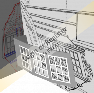
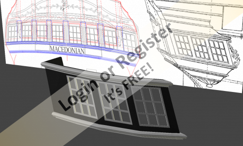
I really liked the modular approach, and simple design. I had already decided to use winch-drums turned vertical in Macedonian, to better handle slack in the braces, AND the tacks and sheets of the course sails.
The drawing shows my plan to control the fore, main, and mizzen tops'l yards, and the fore and main course tacks (fewer yards controlled than on Nurnberg) and a 3D model I made to check clearances and fit.

▲
⟩⟩
TonyAsh
tomarack
hermank
pressonreguardless
RossM
📝 Pride of Paint
8 months ago by 🇺🇸 Jerry Todd ( Sub-Lieutenant)
Sub-Lieutenant)✧ 28 Views · 4 Likes
Flag
💬 Add Comment
While painting things for Constellation, some things for Pride got paint too
▲
⟩⟩
EdW
hermank
chugalone100
RNinMunich
📝 Do and Redo
8 months ago by 🇺🇸 Jerry Todd ( Sub-Lieutenant)
Sub-Lieutenant)✧ 17 Views · 5 Likes · 1 Comment
Flag
💬 Add Comment
Painted the printed grating a more oakish color, but not really matching the wood gratings I made. then I had to chop off some of the head gratings to bet the bowsprit by. Not really happy with any of that, but fixing it will have to wait as I'm gonna be traveling away from home for a bit.
I started painting the hammocks on the portside.
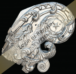
Then I found they had scanned the head ornaments on Constellation, and using screen shot of their models I got 3D files. There's a LOT of work to be done before I can print them, but I'll have 3D printed head carving for the model at last.

I started painting the hammocks on the portside.
Then I found they had scanned the head ornaments on Constellation, and using screen shot of their models I got 3D files. There's a LOT of work to be done before I can print them, but I'll have 3D printed head carving for the model at last.
▲
⟩⟩
thadlietz
stevedownunder
Ronald
RNinMunich
peterd
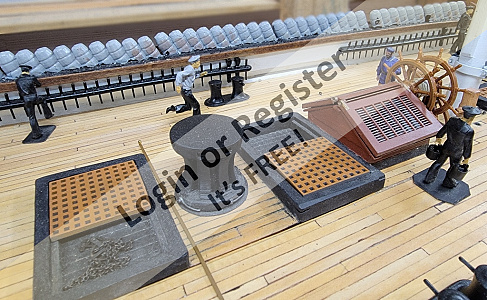
📝 Gratings and Skids
9 months ago by 🇺🇸 Jerry Todd ( Sub-Lieutenant)
Sub-Lieutenant)✧ 29 Views · 7 Likes
Flag
💬 Add Comment
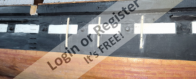
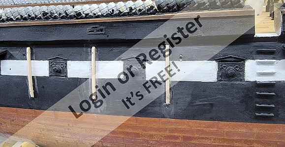
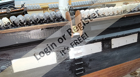
Clamps, ledgers, cleats, whatever, got installed in the head for the grating to sit on, and it all got painted. I made new templates and from them 3D models of (hopefully) better fitting gratings. Being thin and perforated, they wanted to curl, so I glued wood stiffeners to the underside, and they got primer and paint.
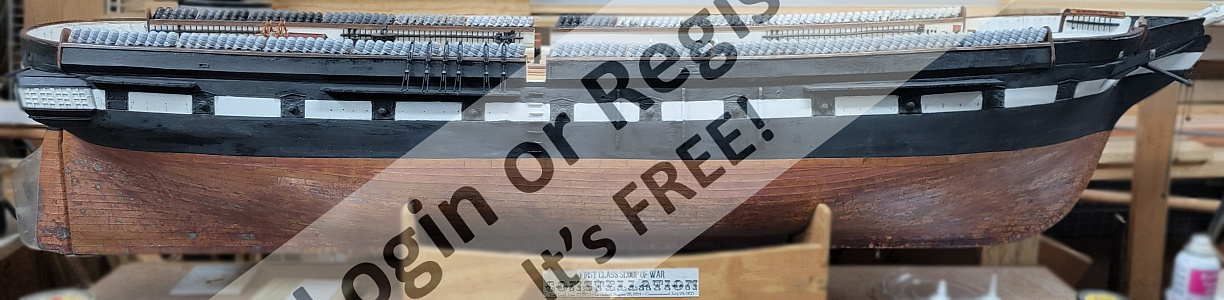
I installed skid rails on the sides when I could see them in the 1856 portrait the model's based on. These were cut to shape, glued, and pinned to the hull. Some primer and paint went on here too.
It's almost time to mask and properly paint the hull nice and neat.
I installed skid rails on the sides when I could see them in the 1856 portrait the model's based on. These were cut to shape, glued, and pinned to the hull. Some primer and paint went on here too.
It's almost time to mask and properly paint the hull nice and neat.
▲
⟩⟩
Ronald
Len1
hermank
EdW
thadlietz
stevedownunder
RNinMunich
📝 Remodeling the Loo
9 months ago by 🇺🇸 Jerry Todd ( Sub-Lieutenant)
Sub-Lieutenant)✧ 36 Views · 7 Likes · 1 Comment
Flag
💬 Add Comment
Painting and clear-coating is done on the crew that's made so far, so I started looking at making gratings for the head.
I made chipboard patterns, scanned them, and used that image as a guide to 3D modeling them. They took 4 hours to print and need some adjustment, but I need to install cleats (ledges) for them to sit on to accurately see how much adjustment is needed.

I made chipboard patterns, scanned them, and used that image as a guide to 3D modeling them. They took 4 hours to print and need some adjustment, but I need to install cleats (ledges) for them to sit on to accurately see how much adjustment is needed.
▲
⟩⟩
hermank
EdW
RNinMunich
Len1
stevedownunder
Ronald
Newby7
📝 Davit and Goliath
10 months ago by 🇺🇸 Jerry Todd ( Sub-Lieutenant)
Sub-Lieutenant)✧ 38 Views · 6 Likes
Flag
💬 Add Comment
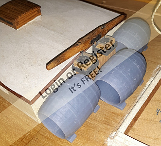
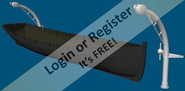
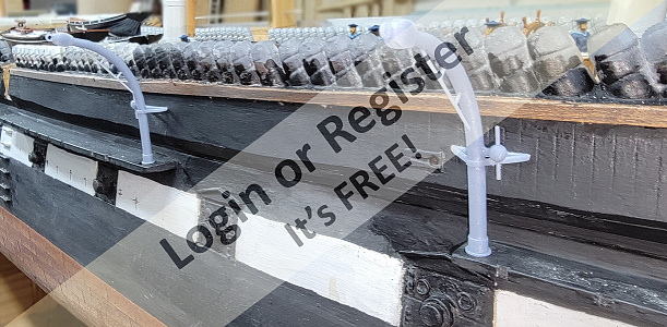
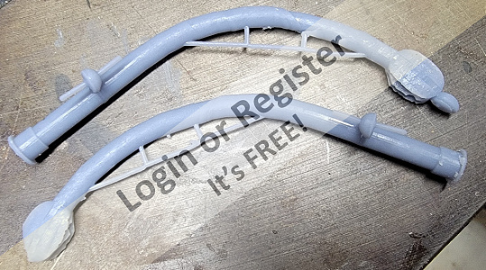
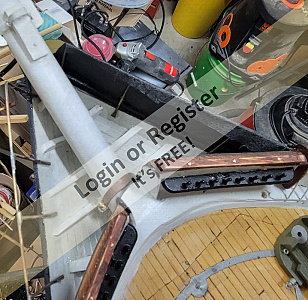
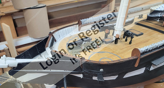
I'm sure the davits had some sort of brace, most likely bolted to the hammock irons that make up the bulwarks, so I mocked something up with chipboard and the last poorly printed davits to get measurements with. I updated the 3D model with that as well as finishing the double block at the top. I replaced the ball at the tip with a ring as it appear there was a chain linking the davits together.
The slicer said it would take 3 hours and 50 minutes to print a pair, but checking the printer 2 hours in, I found it wasn't doing anything. I reset and restarted it and 4 hours later had a pair of davits.
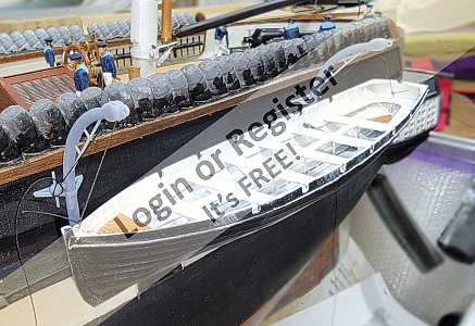
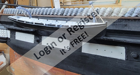
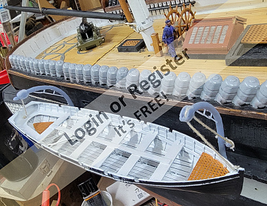
I temporarily CAed them to the channels to see how they looked, and hung a boat from them. I think they'll serve just fine, they look right, at least. I'll drill holes in the bottoms so pins can attach them to the channels better.
The slicer said it would take 3 hours and 50 minutes to print a pair, but checking the printer 2 hours in, I found it wasn't doing anything. I reset and restarted it and 4 hours later had a pair of davits.
I temporarily CAed them to the channels to see how they looked, and hung a boat from them. I think they'll serve just fine, they look right, at least. I'll drill holes in the bottoms so pins can attach them to the channels better.
▲
⟩⟩
EdW
RNinMunich
Len1
stevedownunder
peterd
hermank
📝 More little guys
10 months ago by 🇺🇸 Jerry Todd ( Sub-Lieutenant)
Sub-Lieutenant)✧ 40 Views · 7 Likes
Flag
💬 Add Comment
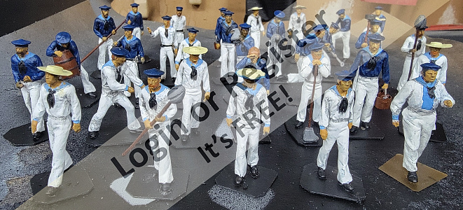
I printed the modified files, 7 straw hats, and the sponger. I made the hat brims too thin, and they didn't print well, so I made brims from paper, painted them with resin from the printer ; and hardened the resin with UV light. This batch of 15 is mostly painted, but still needs some details and touch-up.
This will make 32 crew, and I have to make guys climbing the rig, laying out on the yards, sitting around, plus some officers and Marines. I'm guessing it's going to wind up being 50 or more figure in total.
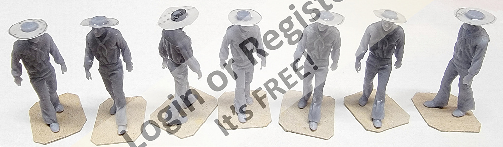
This will make 32 crew, and I have to make guys climbing the rig, laying out on the yards, sitting around, plus some officers and Marines. I'm guessing it's going to wind up being 50 or more figure in total.
▲
⟩⟩
EdW
Steves-s
Len1
hermank
stevedownunder
Fred
SimpleSailor
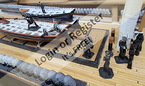
💬 Re: Now in Color
10 months ago by 🇺🇸 Jerry Todd ( Sub-Lieutenant)
Sub-Lieutenant)✧ 48 Views · 4 Likes
Flag
💬 Add Comment
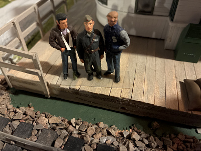
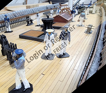
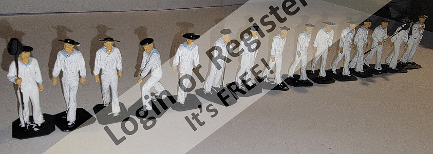
All of them are on bits of card for now, but will be attached to the deck. On stands they'd slide around as the model sailed.
Ivan is standing on a piece of clear plastic, he got his feet wet and the card came off. When he's gone sailing, he was taped down to stay with the boat.
PS: I just printed a few more, though four didn't turn out. In the pic they're cleaned and PVA glued to bit of chipboard, then primed black.

Ivan is standing on a piece of clear plastic, he got his feet wet and the card came off. When he's gone sailing, he was taped down to stay with the boat.
PS: I just printed a few more, though four didn't turn out. In the pic they're cleaned and PVA glued to bit of chipboard, then primed black.
▲
⟩⟩
SimpleSailor
Len1
EdW
hermank
📝 Now in Color
10 months ago by 🇺🇸 Jerry Todd ( Sub-Lieutenant)
Sub-Lieutenant)✧ 53 Views · 11 Likes · 3 Comments
Flag
💬 Add Comment
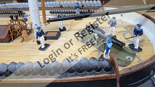
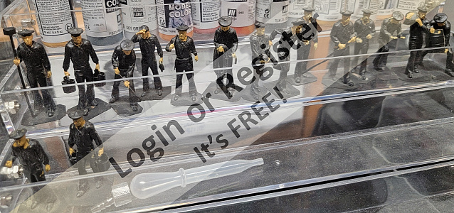
I ordered some white, black, and blue acrylics, and paint half my little crew as soon as they came in, including Ivan.
Ivan came from a $5 kit of WWII Soviet Naval soldiers, an was the models first crewman whose job it was to be in pictures to give a sense of scale. He even survived the 2011 Earthquake!
Ivan got new paint to match the other crewmen, will remain "clean shaven," and will be posted at the helm.
I had to order more paint as I didn't have anything for things like hair colors, buckets, or casks.
▲
⟩⟩
Steves-s
SimpleSailor
Rookysailor
EdW
luckyduck
Len1
stevedownunder
hermank
RNinMunich
peterd
Wolle
Login To
Remove Ads
Remove Ads
📝 Bonehead Strikes Again!
10 months ago by 🇺🇸 Jerry Todd ( Sub-Lieutenant)
Sub-Lieutenant)✧ 60 Views · 10 Likes · 2 Comments
Flag
💬 Add Comment
Years ago, the lady opened the garage door while I had the full rig up, and snapped off the mizzen topmast and main mast head. I repaired it, though it was difficult as the mast and topmasts are made of white cedar and gluing end-grain does do well at all.
In a photo in the last post, in the upper left of the photo, there are some gray tubes stored up in the garage door tracks. A little over a week ago, I moved the model, with the topmasts un-shipped and t'gallants up, as in the photo, and snapped of the mizzen topmast right at the previous repair. I epoxied it back together, a little sloppily, but I was gonna clean it up later.
Instead, I went and snapped it off again, this time at the doubling. I tried to repair it again, but it was to weak to be of use.
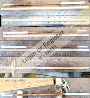
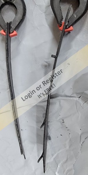
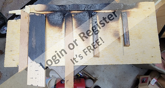
So I made a new mizzen topmast. I don't have any more white cedar long enough, so I used bit of yellow pine from an old cabinet I scavenged some wood from. The picture shows the steps in making the new spar.
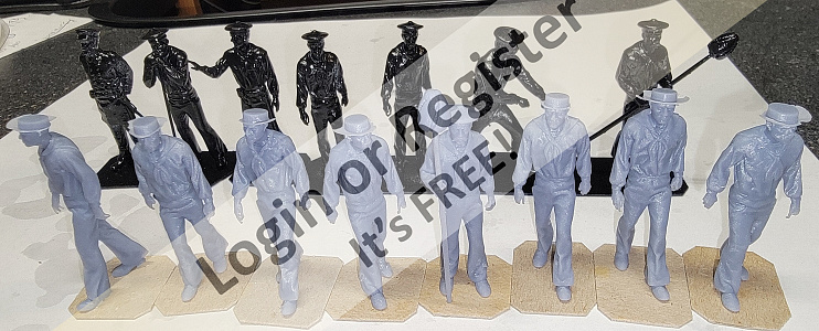
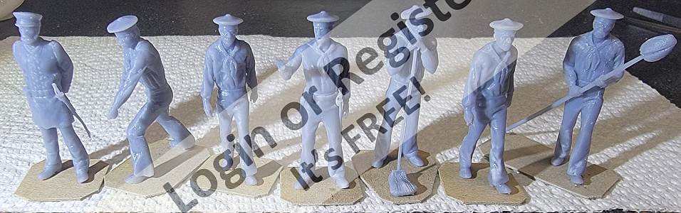
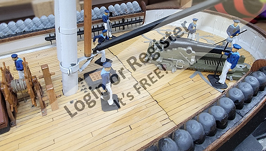
Today being a one step forward two steps back kind of day, I started painting the crew figures I 3D printed. These guys are on a portion of the 30-40 squids, marines, officers, and a cat, I plan to man the ship. I don't have the 1850's marine figures, I need to repose a few sailors, and the officer need dis-arming and reposing.
In a photo in the last post, in the upper left of the photo, there are some gray tubes stored up in the garage door tracks. A little over a week ago, I moved the model, with the topmasts un-shipped and t'gallants up, as in the photo, and snapped of the mizzen topmast right at the previous repair. I epoxied it back together, a little sloppily, but I was gonna clean it up later.
Instead, I went and snapped it off again, this time at the doubling. I tried to repair it again, but it was to weak to be of use.
So I made a new mizzen topmast. I don't have any more white cedar long enough, so I used bit of yellow pine from an old cabinet I scavenged some wood from. The picture shows the steps in making the new spar.
Today being a one step forward two steps back kind of day, I started painting the crew figures I 3D printed. These guys are on a portion of the 30-40 squids, marines, officers, and a cat, I plan to man the ship. I don't have the 1850's marine figures, I need to repose a few sailors, and the officer need dis-arming and reposing.
▲
⟩⟩
Len1
Wolle
stevedownunder
AustinG
hermank
RNinMunich
ToraDog
RossM
SimpleSailor
EdW
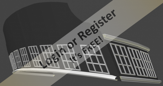
📝 Privacy in the Heads
10 months ago by 🇺🇸 Jerry Todd ( Sub-Lieutenant)
Sub-Lieutenant)✧ 62 Views · 6 Likes
Flag
💬 Add Comment
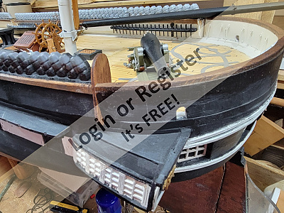
The screens are up, laced, and painted. The tars can have a little privacy while contemplating what that was Cookie fed them. That reminds me, I have to put in the seats and the poop-chute yet.
Well, the sheer runs the full length of the boat now.
Well, the sheer runs the full length of the boat now.
▲
⟩⟩
Len1
Wolle
SimpleSailor
EdW
hermank
stevedownunder
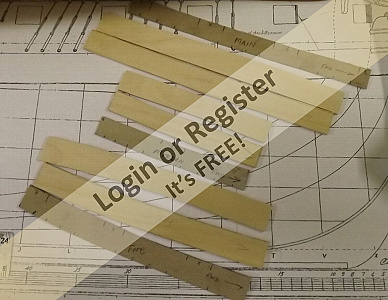
💬 Re: Tarpaulin
10 months ago by 🇺🇸 Jerry Todd ( Sub-Lieutenant)
Sub-Lieutenant)✧ 64 Views · 2 Likes
Flag
💬 Add Comment
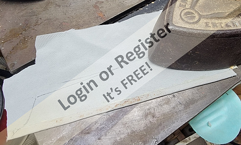
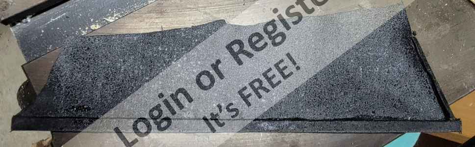
Actually Gray Supplex spray-painted black.
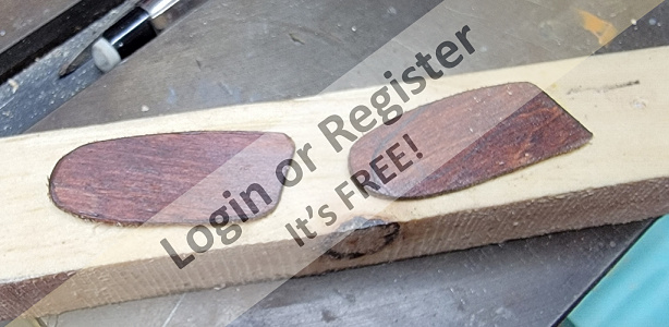
I got a couple of yards to make Macedonian's sails and snipped off some bits to do this.

I got a couple of yards to make Macedonian's sails and snipped off some bits to do this.
▲
⟩⟩
Len1
hermank
📝 Davit Developement
10 months ago by 🇺🇸 Jerry Todd ( Sub-Lieutenant)
Sub-Lieutenant)✧ 66 Views · 7 Likes
Flag
💬 Add Comment
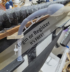
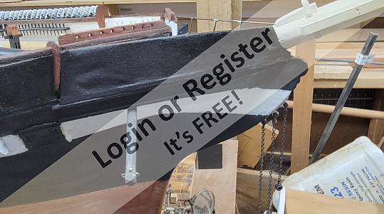
I don't have much to go on as the quarter-boat davits go. The images I have of the time frame I'm modeling the boat, are "impressionistic" at best, and I haven't been able to find technical drawings, manuals, instruction, images of other ships, photos, or anything that really shows what these davits looked like or how they were attached.
The two portraits I'm working from are the one I'm basing the model on from 1856, and one from 1860.
The davits I model previously were nothing like the paintings, so I modified it to what I show here. I printed four, two failed outright, and the two I got wouldn't be usable, but they did help with visualization.
There's some details to work out, beside building the proper double-block to replace the one I just slapped on to get a test model made. I'm there had to be some sort of bracing to the bulwark that's not shown, because the davit doesn't appear to extend below the channels to be braced against the hull.
The davits will be among the last parts to go on the model, so there's no hurry to get them done.
▲
⟩⟩
Len1
EdW
jbkiwi
hermank
Ronald
stevedownunder
SimpleSailor
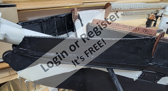
📝 Tarpaulin
10 months ago by 🇺🇸 Jerry Todd ( Sub-Lieutenant)
Sub-Lieutenant)✧ 66 Views · 4 Likes · 2 Comments
Flag
💬 Add Comment
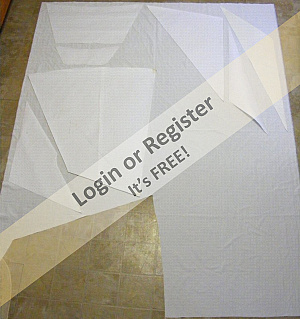
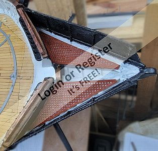
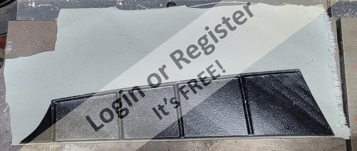
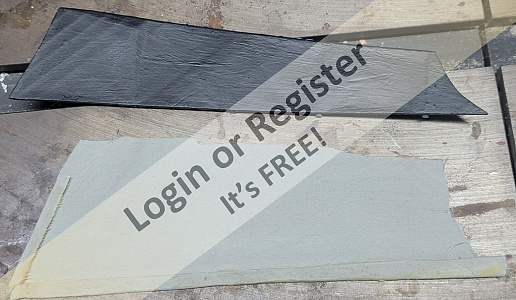
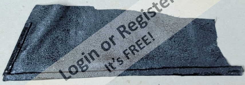
The tarp that goes over the frames I made from some Supplex (cloth I use for my sails) with strips of wood hemmed/glued into the bottom and aft ends. It's left a little long at the top and will get trimmed after it's installed. It was spray-painted black, front and back - two coats.
The reinforced edges are glued to the top-rail of the head and the hull, and the loose part is pulled over the rail and CAed to hold it. It's then laced with Dacron sail thread along the top rail and forward end. The whole thing will get another coat of paint brushed on, but first I have to get the port side to this point.
The reinforced edges are glued to the top-rail of the head and the hull, and the loose part is pulled over the rail and CAed to hold it. It's then laced with Dacron sail thread along the top rail and forward end. The whole thing will get another coat of paint brushed on, but first I have to get the port side to this point.
▲
⟩⟩
Len1
hermank
stevedownunder
SimpleSailor
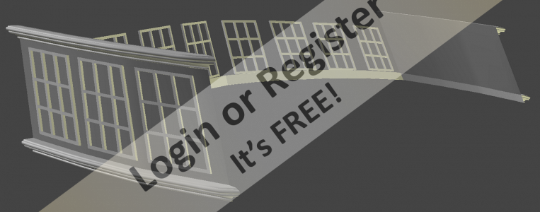
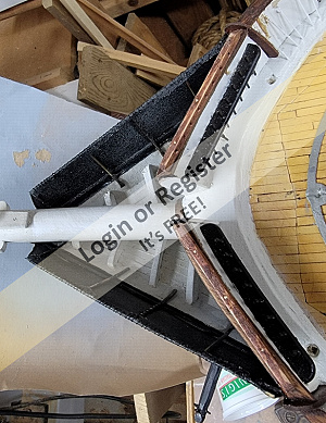
📝 Spray-screens
10 months ago by 🇺🇸 Jerry Todd ( Sub-Lieutenant)
Sub-Lieutenant)✧ 64 Views · 5 Likes
Flag
💬 Add Comment
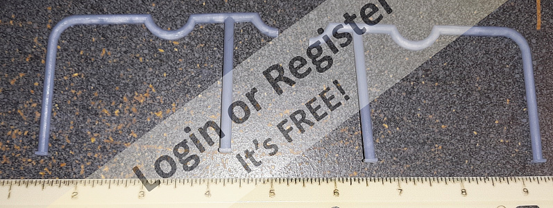
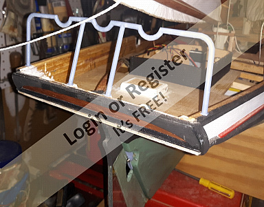
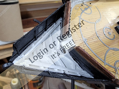
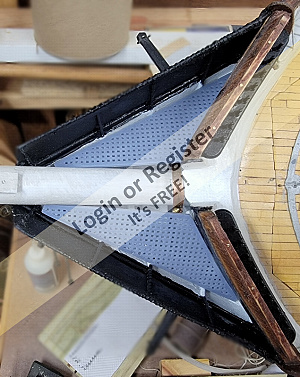
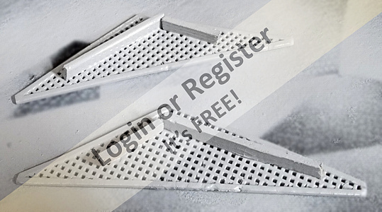
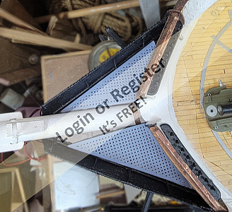
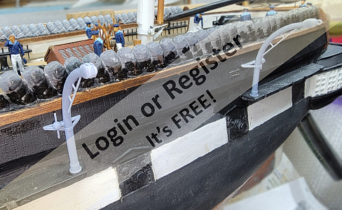
The 3D printed spray-screens curled, and I wasn't satisfied they'd stand up, even to being installed, without snapping in half at some point.
So I went back to plan A which was to make the frame in brass rod (1/16") and make the screen either of painted cloth (which is basically what the original was) or styrene or PVC sheet.
The legs of the frames or rails are flattened where they attach to the head to give some gluing surface, and installed with CA, then reinforced with epoxy.
The last pic's of the jig I soldered the frame on. It's a bit cooked, but it did the job
▲
⟩⟩
hermank
SimpleSailor
premecekcz
stevedownunder
Len1
📝 Oops
11 months ago by 🇺🇸 Jerry Todd ( Sub-Lieutenant)
Sub-Lieutenant)✧ 65 Views · 7 Likes
Flag
💬 Add Comment
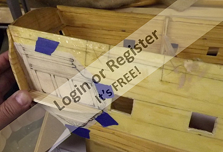
Well, not that big of an oops, but I forgot to put in two smaller end-boards at the end of the fixed bulwarks where the box pin-rails are.
So, I cut the parts from the old thin basswood end-board I was replacing with thicker ones, and installed these over-looked pieces.
The I installed the new, thicker end-boards except for one, which I have to turn the model around again to get at. Once that piece is installed, it'll pretty much be done with the railings and end-boards.
I think the spray-screens will be next, and I think it might mean moving away from 3D printing...
▲
⟩⟩
SimpleSailor
premecekcz
Len1
hermank
Wolle
Fred
stevedownunder
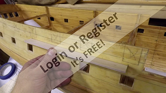
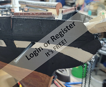
📝 End-boards
11 months ago by 🇺🇸 Jerry Todd ( Sub-Lieutenant)
Sub-Lieutenant)✧ 63 Views · 8 Likes · 1 Comment
Flag
💬 Add Comment
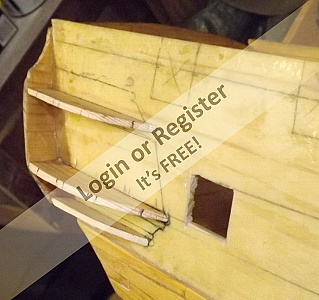
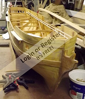
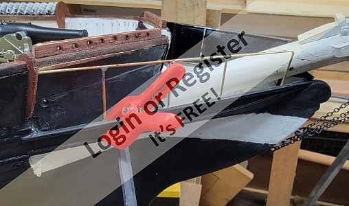
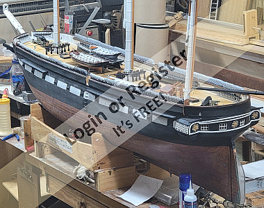
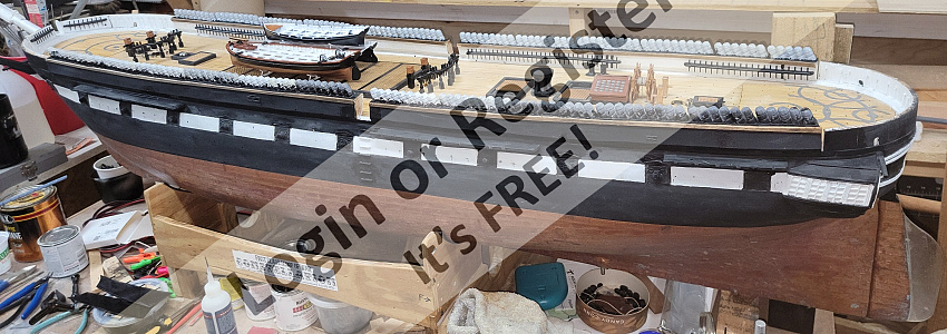
I made 4 new end-boards from some thin plywood, which require opening the space between the bulwarks and the drop-panels so they'd fit. I have to turn the hull to get at the starboard side, so they aren't installed yet, but I stuck them at the entry-port just for a pic.
▲
⟩⟩
peterd
SimpleSailor
premecekcz
Len1
hermank
Fred
Ronald
stevedownunder
📝 railing on the rails
11 months ago by 🇺🇸 Jerry Todd ( Sub-Lieutenant)
Sub-Lieutenant)✧ 63 Views · 6 Likes
Flag
💬 Add Comment
The pin-rails and trim boards installed, I went about putting the cap-rails on the drop-panel portions of the bulwarks fore and aft.
These were cut from a 3/16" thick board a friend left from making a guitar at my shop some years ago, using a card template traced from the bulwarks themselves.
Probably better described as "log" over "rails," since they were fairly rough made, each panel would have had their own section, but since I didn't model the function of the panels, I made the rail in one piece, and scored it where the breaks would be. Once fitted, it was stained, darkening those score lines. It was drilled for the round-toothpick pins that would help fasten it to the bulwarks, besides just being glued to the top.
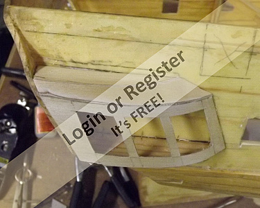
The end-boards with round tops at the ends of the bulwarks, are just sitting there. I plan to make slightly thicker ones for permanent placement. The ones that frame the entry-port were carved, and I'm trying to 3D model those with no success so far.
As a placeholder, I printed the carvings on paper and glued that to blank end-boards. Anyway, these will probably go on next along with the spray-screens up on the head.


These were cut from a 3/16" thick board a friend left from making a guitar at my shop some years ago, using a card template traced from the bulwarks themselves.
Probably better described as "log" over "rails," since they were fairly rough made, each panel would have had their own section, but since I didn't model the function of the panels, I made the rail in one piece, and scored it where the breaks would be. Once fitted, it was stained, darkening those score lines. It was drilled for the round-toothpick pins that would help fasten it to the bulwarks, besides just being glued to the top.
The end-boards with round tops at the ends of the bulwarks, are just sitting there. I plan to make slightly thicker ones for permanent placement. The ones that frame the entry-port were carved, and I'm trying to 3D model those with no success so far.
As a placeholder, I printed the carvings on paper and glued that to blank end-boards. Anyway, these will probably go on next along with the spray-screens up on the head.
▲
⟩⟩
SimpleSailor
hermank
Len1
EdW
stevedownunder
RNinMunich
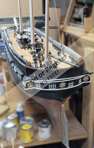
📝 Bulwarks done-ish
11 months ago by 🇺🇸 Jerry Todd ( Sub-Lieutenant)
Sub-Lieutenant)✧ 62 Views · 8 Likes
Flag
💬 Add Comment
The port-side pin-rails are on, and the trim-boards, inboard and outboard, installed. I still need to find, or mix, a paint color that look like canvas for the hammocks; I don't like the gray.
Now I've got to make the rest of the chainplates for the shrouds so actual rigging can start.


Now I've got to make the rest of the chainplates for the shrouds so actual rigging can start.
▲
⟩⟩
SimpleSailor
chugalone100
hermank
Len1
stevedownunder
EdW
peterd
RNinMunich
Login To
Remove Ads
Remove Ads
📝 Paint and glue and paint and glue...
11 months ago by 🇺🇸 Jerry Todd ( Sub-Lieutenant)
Sub-Lieutenant)✧ 62 Views · 11 Likes · 1 Comment
Flag
💬 Add Comment
With the starboard bulwark pretty much done, I ground the outboard edge of the port-side hammocks trays flush and turned the boat around. I then ground the inboard side flush and installed the trim-board. Some painting was done to the hammock trays as well.
I printed a spider-band for the mizzen mast.
Painted the gratings in the boats.
Attached the boat cradles to the main hatch-cover.
Glued on the other bow pin-rail.
Did a test print of the spray-screen on the enclosed head, adjusted the 3D model and printed it again, though I may have to adjust the port-side one some more to make it work as my sloppy workmanship left it a bit asymmetrical.
▲
⟩⟩
SimpleSailor
chugalone100
Len1
EdW
peterd
B rian J ames
hermank
stevedownunder
ToraDog
Wolle
RossM
📝 Wet Bulb
11 months ago by 🇺🇸 Jerry Todd ( Sub-Lieutenant)
Sub-Lieutenant)✧ 41 Views · 7 Likes
Flag
💬 Add Comment
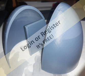
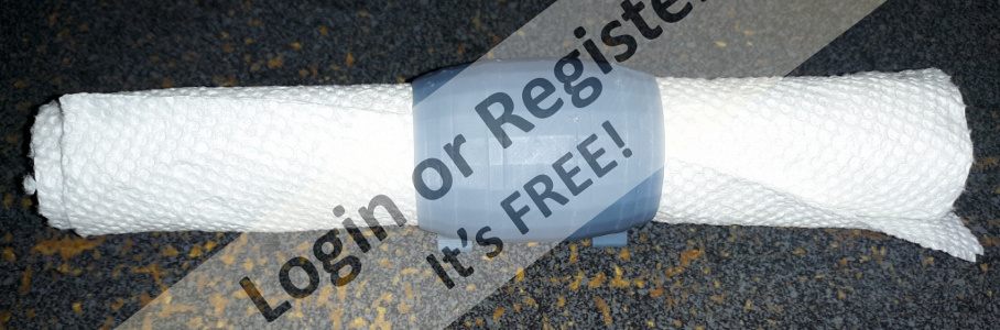
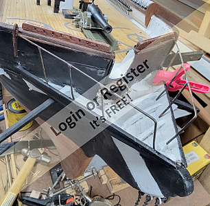
The bulb, aside from paint drying, is basically done!
In total, 3 coats of epoxy, 2 coats of primer, and 2 coats of Moss Green paint, to match the hull.
The thin epoxy ran all over the place with me, brush in hand, chasing it, best I could; but there's still drags and runs, but it's encased in epoxy and functional. Now to see it in the boat.


In total, 3 coats of epoxy, 2 coats of primer, and 2 coats of Moss Green paint, to match the hull.
The thin epoxy ran all over the place with me, brush in hand, chasing it, best I could; but there's still drags and runs, but it's encased in epoxy and functional. Now to see it in the boat.
▲
⟩⟩
SimpleSailor
hermank
chugalone100
RodC
DuncanP
SouthportPat
RossM
📝 Epoxying the bulb
11 months ago by 🇺🇸 Jerry Todd ( Sub-Lieutenant)
Sub-Lieutenant)✧ 43 Views · 8 Likes
Flag
💬 Add Comment
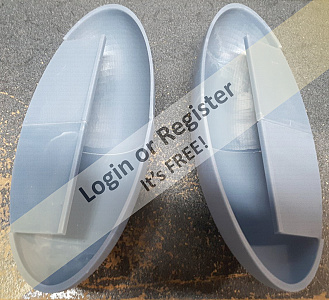
It turned out to be a nice day, so after mowing, I got out the disk sander and sanded the lumpy bulb out in the driveway. It was quicker work than I expected, so I mixed up some epoxy (without sawdust) and coated the thing. This is sold as "pouring epoxy" so it's pretty runny, and takes a while to set.
Once it set , it got a sand and another lite coat of epoxy; then it was sanded and primed - twice; then sanded and painted Moss Green - twice. I think that just about does it for the ballast bulb.


Once it set , it got a sand and another lite coat of epoxy; then it was sanded and primed - twice; then sanded and painted Moss Green - twice. I think that just about does it for the ballast bulb.
▲
⟩⟩
SimpleSailor
hermank
chugalone100
RodC
premecekcz
Peejay
SouthportPat
RossM
📝 Epoxy on the Bulb
11 months ago by 🇺🇸 Jerry Todd ( Sub-Lieutenant)
Sub-Lieutenant)✧ 50 Views · 6 Likes · 1 Comment
Flag
💬 Add Comment
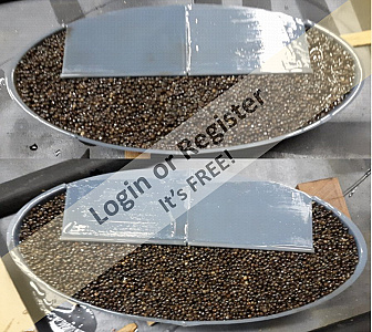
I mixed up epoxy and sawdust for gluing on Constellation's pin-rails, and made some extra to"glass" Pride's ballast-bulb. Instead of glass cloth, I use a piece of pantyhose. Despite the sawdust, the epoxy was still rather thin, and kept running out of the gap I was trying to fill, while I chased it with a stick trying to keep it in there.
It's going to require some sanding, but it'll have to wait till it decides to quit raining, cause I'm not doing that inside.

It's going to require some sanding, but it'll have to wait till it decides to quit raining, cause I'm not doing that inside.
▲
⟩⟩
SimpleSailor
chugalone100
Peejay
hermank
SouthportPat
RossM
📝 Back to work watching paint dry
11 months ago by 🇺🇸 Jerry Todd ( Sub-Lieutenant)
Sub-Lieutenant)✧ 55 Views · 5 Likes
Flag
💬 Add Comment
Made boat cradles for the ship's boats, blocks, and new bitts. Some of the blocks are shells meant to get 8mm brass sheaves for use on moving things like the braces, etc. The others are "static" that don't move, much; for things like halyards. I couldn't find anyone with 8mm sheave in stock, so I printed some in resin. I also printed a set of smaller blocks; some will use 6mm brass sheaves, and some are static.
Next was installing the pin-rails from the prior post, but some work had to happen first;
First was dusting and cleaning them model and positioning it so I could get at where I needed to work.
The Hammocks were made as trays a little wide to accommodate any irregularities in the bulwarks, this excess needed to be grinded down flush with the inside surface. The any gaps were filled with a putty of epoxy and sawdust.
The inside surface and the hammocks all got painted, and when dry, a covering board of stained basswood was glued on to cover the seam between hammocks and bulwark. I'm not happy with the hammocks color, it should be leaning more toward tan than gray, but work on that later.
I had already drilled the pin-rails for mounting pins, those holes needed to transfer to the bulwarks. I made the 3D pin-rails based on measurements taken from the actual ship, but my "covering-board" is a little thick, so there's not much room between the belaying pins and the bulwark. I addressed this by padding the pin-rails with 1/16" basswood.
This is as far as I've gotten on the starboard side. Installing the pin-rails is next, then it's spin the hull around and do all that for the port side.
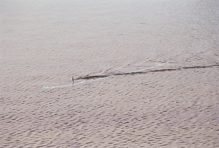
The boats got paint and clear-coat and one even got to go for a swim 😊
Work-log on my site:


Next was installing the pin-rails from the prior post, but some work had to happen first;
First was dusting and cleaning them model and positioning it so I could get at where I needed to work.
The Hammocks were made as trays a little wide to accommodate any irregularities in the bulwarks, this excess needed to be grinded down flush with the inside surface. The any gaps were filled with a putty of epoxy and sawdust.
The inside surface and the hammocks all got painted, and when dry, a covering board of stained basswood was glued on to cover the seam between hammocks and bulwark. I'm not happy with the hammocks color, it should be leaning more toward tan than gray, but work on that later.
I had already drilled the pin-rails for mounting pins, those holes needed to transfer to the bulwarks. I made the 3D pin-rails based on measurements taken from the actual ship, but my "covering-board" is a little thick, so there's not much room between the belaying pins and the bulwark. I addressed this by padding the pin-rails with 1/16" basswood.
This is as far as I've gotten on the starboard side. Installing the pin-rails is next, then it's spin the hull around and do all that for the port side.
The boats got paint and clear-coat and one even got to go for a swim 😊
Work-log on my site:

▲
⟩⟩
chugalone100
EdW
hermank
Wolle
stevedownunder
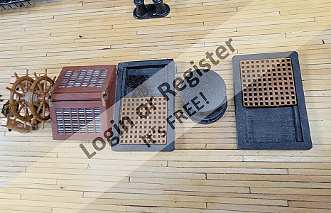
📝 More details
1 year ago by 🇺🇸 Jerry Todd ( Sub-Lieutenant)
Sub-Lieutenant)✧ 39 Views · 3 Likes
Flag
💬 Add Comment
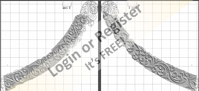
Modeled and printed some gunport lids, cat head cat faces (note these are 1cm sqare, so won't have much detail), and one of 7 sizes of deadeyes.
It might get warm enough to paint a little, or it might blizzard, depends on which channel you watch.


It might get warm enough to paint a little, or it might blizzard, depends on which channel you watch.
▲
⟩⟩
tomarack
Peejay
RNinMunich
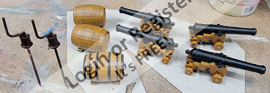
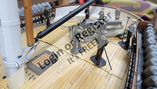
📝 Guns and then some
1 year ago by 🇺🇸 Jerry Todd ( Sub-Lieutenant)
Sub-Lieutenant)✧ 45 Views · 4 Likes
Flag
💬 Add Comment
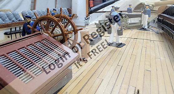
All the guns and carriages needed are printed, a some extras. Also made the ship's wheel from the 3D model of Constellation's wheel.
There's still a bunch of things to model and print; blocks, gunport lids,hearts, bullseyes, fairleads, crew, anchors, and a lot of other stuff.


There's still a bunch of things to model and print; blocks, gunport lids,hearts, bullseyes, fairleads, crew, anchors, and a lot of other stuff.
▲
⟩⟩
tomarack
Peejay
RNinMunich
luckyduck
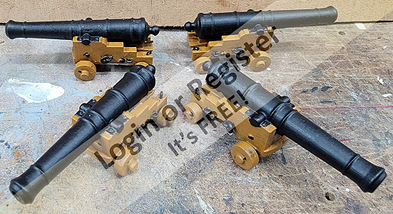
📝 Great Guns
1 year ago by 🇺🇸 Jerry Todd ( Sub-Lieutenant)
Sub-Lieutenant)✧ 50 Views · 7 Likes
Flag
💬 Add Comment
I have all the 18 pounder tubes printed, and half the carriages


▲
⟩⟩
tomarack
Peejay
luckyduck
jumpugly
RNinMunich
hermank
Ray
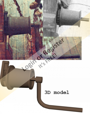
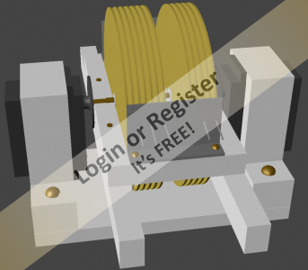
📝 Printing the Capstan
1 year ago by 🇺🇸 Jerry Todd ( Sub-Lieutenant)
Sub-Lieutenant)✧ 53 Views · 7 Likes
Flag
💬 Add Comment
I "test-printed" the capstan and the section of the disks where the sockets for the capstan bars were didn't print. The hole in the bottom capstan didn't go all the way through. So I reworked the disk section of both the upper and lower capstans and printed it again. This time it printed - mostly. The hole in the bottom printed over again (haven't figured that one out) and there were a couple of flaw around some of those sockets (which I'll putty up when paint time comes) It's usable at least and I'm marking it done.


▲
⟩⟩
tomarack
Peejay
RNinMunich
luckyduck
hermank
Chuck
jumpugly
Login To
Remove Ads
Remove Ads