Join Us On Social Media!

|

|

|
Download The App!


Login To
Remove Ads
Remove Ads
Login To
Remove Ads
Remove Ads
Model Boats Website
Revell 1:142, Northsea Fishing Trawler build & RC conversion.
3 Posts · 2 Followers · 16 Photos · 1 Like
Began 5 hours ago by
 Australia
Follow This Thread
Not currently following
> Click to follow
> Click to follow
Latest Post 28 minutes ago by
| Most recent posts shown first (Show Oldest First) | (Print Booklet) |
📝 Revell 1:142, Northsea Fishing Trawler build & RC conversion.
28 minutes ago by 🇦🇺 stevedownunder ( Commodore)
Commodore)✧ 2 Views · 0 Likes
Flag
💬 Add Comment
Hi Ron,
So far I haven't fully tested the sea worthyness of this model to it's full extent however she rides up the waves quite nicly, and is affected by cross winds more than waves, so far there have not been any alarming handeling characteristics.
So far I haven't had a capsize with any of my boats, I generally try to keep any topsides weight to a minimum.
Cheers,
Stephen.
So far I haven't fully tested the sea worthyness of this model to it's full extent however she rides up the waves quite nicly, and is affected by cross winds more than waves, so far there have not been any alarming handeling characteristics.
So far I haven't had a capsize with any of my boats, I generally try to keep any topsides weight to a minimum.
Cheers,
Stephen.
▲
⟩⟩
No likes yet
This member will receive 1 point
for every like received
This member will receive 1 point
for every like received
Login To
Remove Ads
Remove Ads
📝 Revell 1:142, Northsea Fishing Trawler build & RC conversion.
4 hours ago by 🇦🇺 stevedownunder ( Commodore)
Commodore)✧ 10 Views · 0 Likes · 1 Comment
Flag
💬 Add Comment
Hi Ron,
Not much if any ballast was needed, maybe some trimming ballast was used but thats all.
This is quite a small model.
Cheers,
Stephen.
Not much if any ballast was needed, maybe some trimming ballast was used but thats all.
This is quite a small model.
Cheers,
Stephen.
▲
⟩⟩
No likes yet
This member will receive 1 point
for every like received
This member will receive 1 point
for every like received
|
💬 Re: Revell 1:142, Northsea Fishing Trawler build & RC conversion.
3 hours ago by 🇨🇦 Ronald (
 Fleet Admiral) Fleet Admiral)✧ 10 Views · 2 Likes
Flag
But you said you like your models to be able to sail through rough weather. What do you do then to make sure they do not capsize? How do you ensure they are able to sail up the wave and then down the other side, shipping the waves as it moves along?
▲
⟩⟩
stevedownunder
chugalone100
|

📝 Revell 1:142, Northsea Fishing Trawler build & RC conversion.
5 hours ago by 🇦🇺 stevedownunder ( Commodore)
Commodore)✧ 10 Views · 1 Like · 1 Comment
Flag
💬 Add Comment
Part 1.
This project is already finished, the following is a discription of what was done to build and convert the kit to RC.
Because of severe time restraints at the end of 2022 and foreseeing a similar problem during 2023 and beyond, I decided to stop working on my LT100 trawler build. I thought a plastic kit might be a good idea.
I then had an add pop up from a hobby shop in Australia for this little Trawler kit that has been around for a very long time.
Long enough ago that my father had converted this kit to a working model for my brother and myself to play with when we were kids, all be it a simple electric motor battery and switch, about all you would expect in the mid 1970s, fond memory's of this came back when I saw the kit.
After a quick look on You Tube to see if anyone had put RC into this model successfully, I quickly found a couple of videos of converted models getting around on ponds.
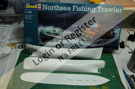
A kit was ordered and quickly came to my house, on opening the box I found a fairly simple kit not much flash the hull halves fitted together quite well. The main complaint I had was how some of the details are quite “blobby” then considering the age of the kit this is justifiable. A quick search on Scalemates tells me that the kit was originally released in 1970 and has had multiple updates to decals and paint schemes, in it’s latest form it represents the Ross Jackal. I also found a couple of build logs on the net these helped me with looking at what might be some good things to alter.
Next I ordered some micro servos a speed controller a small amount of Photo Etch and had a look at how I might implement a conversion.
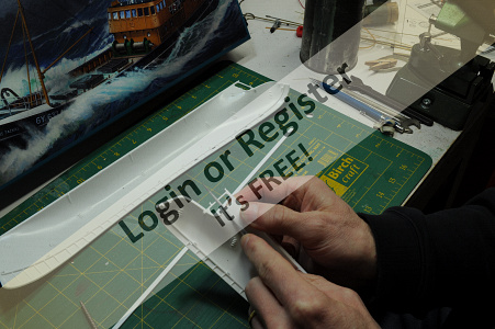
I had some 3mm thin walled Stainless Steel tube that looked like the right size for a custom made prop-shaft, so I started filing the hull halves to open up the prop-shaft area and see if I could fit the tube in. I was very careful while doing this as there was no real room for error.
Once I was satisfied with the result I started making bushes for the shaft.
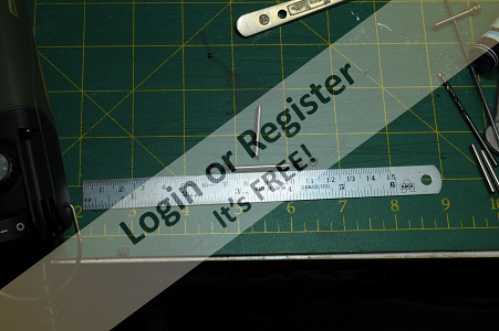
While I was using the lathe I made up an aligning tool to align the shaft and motor, this simply being a good fit in both the motor and prop-shaft. I made this a little on the long side as I didn’t quite know where the motor would sit or how long the shaft would end up, easier to shorten than lengthen.
Some tube was cut, one for the shaft the other for an oiling tube.
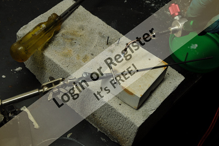
The 2 pieces of tube were silver soldered together using my new micro torch, with LPG and oxygen.
Next job was to make a rudder post and rudder with an actuating lever, brass being used for these components.
Actuating lever and bush along with rudder to rudder post were soft soldered together.
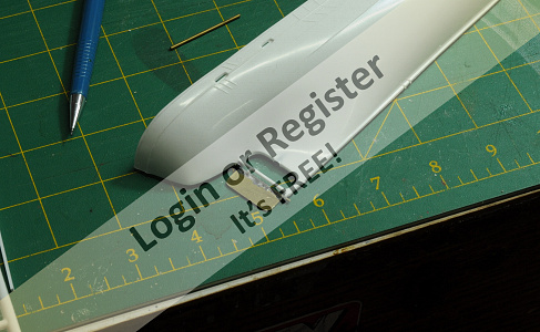
Next thing was to add another anchor recess, modifying a plastic kit in this way is something I haven’t done before, it turned out to be a fairly simple job and quite rewarding.
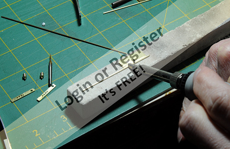
Another mod was to add some more freeing ports along the bulwarks to at least get something closer to the appropriate number, with the help of a build log that explained how to do this I had a go at it and was quite happy with the result. Using a piece of Brass shaped to roughly the right shape it was heated up and pushed into the pre-marked locations to produce a freeing port.
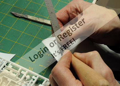
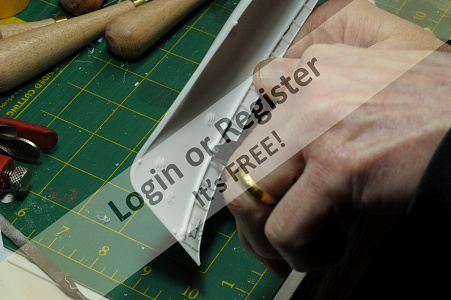
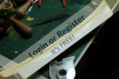
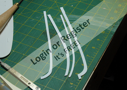
Due to the fact that I like my models to be able to handle heavy weather without fear of sinking, I wanted to seal the deck to the hull. To do this I removed the tabs that are there to help support the deck and replaced them with a continuous ledge, with the hope this will help me make a water tight seal between the deck and hull.
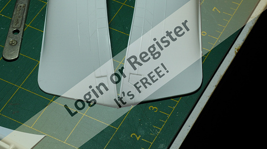
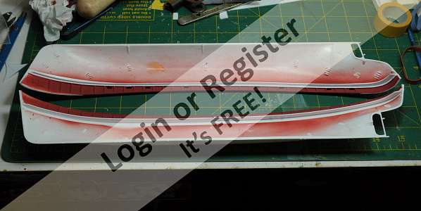
Before gluing the hull halves together I masked and painted the bulwarks, I felt this would be difficult to do later. I also added the new deck supports.
Thank you for reading this post.
Please feel free to comment.
Cheers,
Stephen.




This project is already finished, the following is a discription of what was done to build and convert the kit to RC.
Because of severe time restraints at the end of 2022 and foreseeing a similar problem during 2023 and beyond, I decided to stop working on my LT100 trawler build. I thought a plastic kit might be a good idea.
I then had an add pop up from a hobby shop in Australia for this little Trawler kit that has been around for a very long time.
Long enough ago that my father had converted this kit to a working model for my brother and myself to play with when we were kids, all be it a simple electric motor battery and switch, about all you would expect in the mid 1970s, fond memory's of this came back when I saw the kit.
After a quick look on You Tube to see if anyone had put RC into this model successfully, I quickly found a couple of videos of converted models getting around on ponds.
A kit was ordered and quickly came to my house, on opening the box I found a fairly simple kit not much flash the hull halves fitted together quite well. The main complaint I had was how some of the details are quite “blobby” then considering the age of the kit this is justifiable. A quick search on Scalemates tells me that the kit was originally released in 1970 and has had multiple updates to decals and paint schemes, in it’s latest form it represents the Ross Jackal. I also found a couple of build logs on the net these helped me with looking at what might be some good things to alter.
Next I ordered some micro servos a speed controller a small amount of Photo Etch and had a look at how I might implement a conversion.
I had some 3mm thin walled Stainless Steel tube that looked like the right size for a custom made prop-shaft, so I started filing the hull halves to open up the prop-shaft area and see if I could fit the tube in. I was very careful while doing this as there was no real room for error.
Once I was satisfied with the result I started making bushes for the shaft.
While I was using the lathe I made up an aligning tool to align the shaft and motor, this simply being a good fit in both the motor and prop-shaft. I made this a little on the long side as I didn’t quite know where the motor would sit or how long the shaft would end up, easier to shorten than lengthen.
Some tube was cut, one for the shaft the other for an oiling tube.
The 2 pieces of tube were silver soldered together using my new micro torch, with LPG and oxygen.
Next job was to make a rudder post and rudder with an actuating lever, brass being used for these components.
Actuating lever and bush along with rudder to rudder post were soft soldered together.
Next thing was to add another anchor recess, modifying a plastic kit in this way is something I haven’t done before, it turned out to be a fairly simple job and quite rewarding.
Another mod was to add some more freeing ports along the bulwarks to at least get something closer to the appropriate number, with the help of a build log that explained how to do this I had a go at it and was quite happy with the result. Using a piece of Brass shaped to roughly the right shape it was heated up and pushed into the pre-marked locations to produce a freeing port.
Due to the fact that I like my models to be able to handle heavy weather without fear of sinking, I wanted to seal the deck to the hull. To do this I removed the tabs that are there to help support the deck and replaced them with a continuous ledge, with the hope this will help me make a water tight seal between the deck and hull.
Before gluing the hull halves together I masked and painted the bulwarks, I felt this would be difficult to do later. I also added the new deck supports.
Thank you for reading this post.
Please feel free to comment.
Cheers,
Stephen.
▲
⟩⟩
chugalone100
|
💬 Re: Revell 1:142, Northsea Fishing Trawler build & RC conversion.
4 hours ago by 🇨🇦 Ronald (
Fleet Admiral)✧ 10 Views · 1 Like
Flag
What ballast have you used?
▲
⟩⟩
stevedownunder
|















Login To
Remove Ads
Remove Ads