Join Us On Social Media!

|

|

|
Download The App!
Login To
Remove Ads
Remove Ads
Login To
Remove Ads
Remove Ads
Model Boats Website
Constellation
56 Posts · 16 Followers · 631 Photos · 344 Likes
Began 7 years ago by
 United States
Follow This Thread
Not currently following
> Click to follow
> Click to follow
Latest Post 24 days ago by
| Oldest posts shown first (Show Newest First) | (Print Booklet) |
📝 Constellation
7 years ago by 🇺🇸 Jerry Todd ( Midshipman)
Midshipman)✧ 86 Views · 7 Likes · 3 Comments
Flag
💬 Add Comment
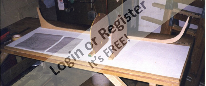
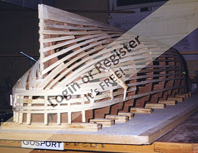
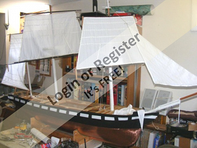
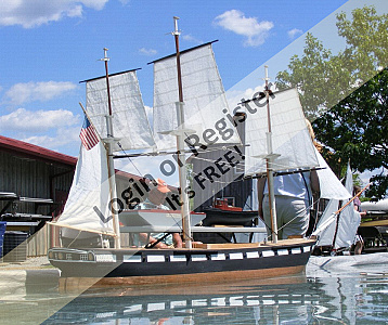
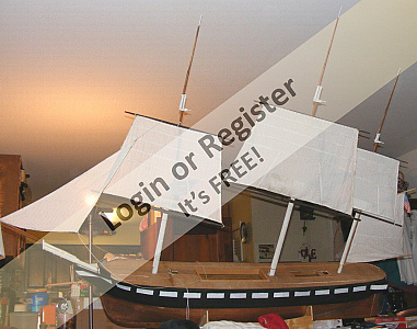
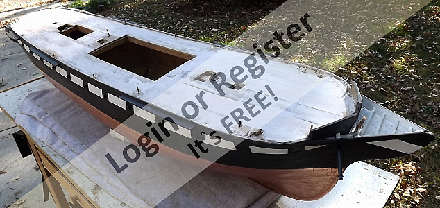
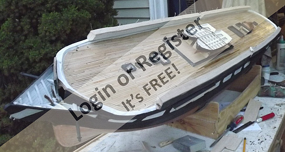
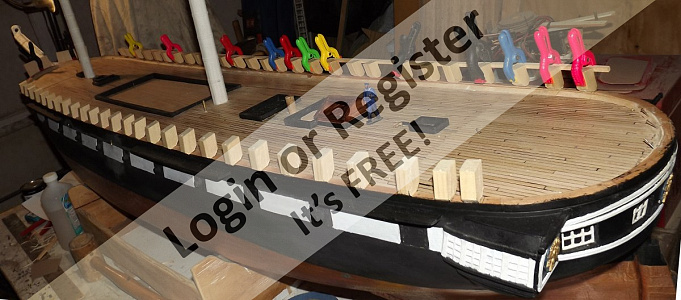
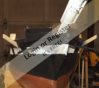
This model was started in February of 1999, and has been worked on, at best, in fits and starts. While progress has been made, and it's capable of sailing, it's far from finished.
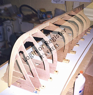
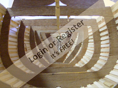
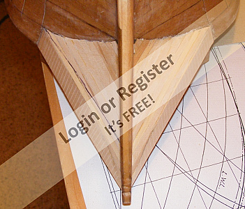
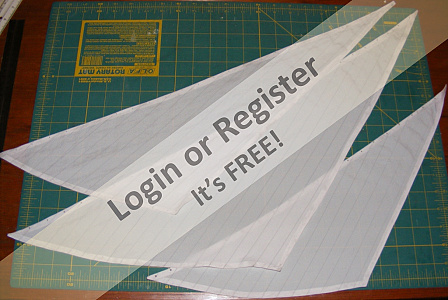
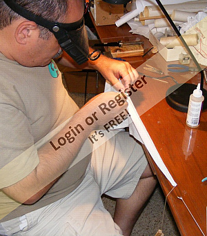
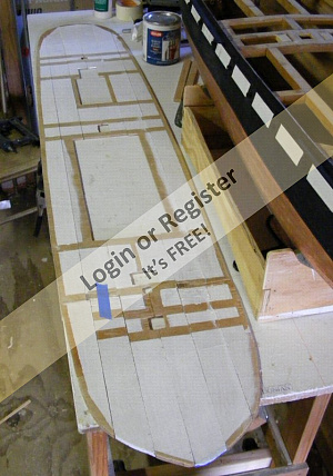
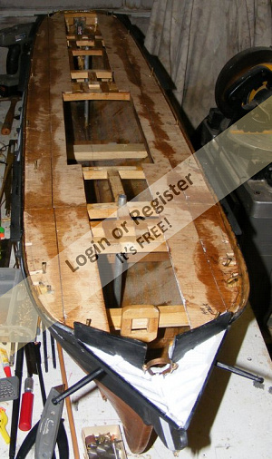
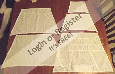
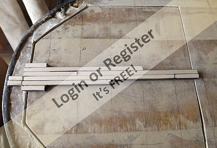
It began as plywood paneling pulled from the walls of my first house and cut into frames. it was to be planked with white pine strips, also scraps from remodeling, but I was distracted by a book. Nasty things books, put all sorts of ideas in your head.
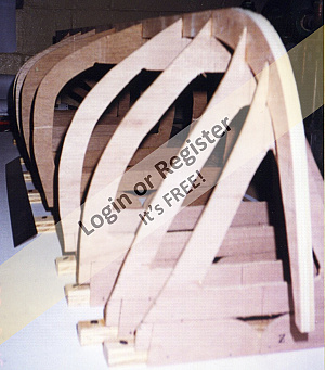
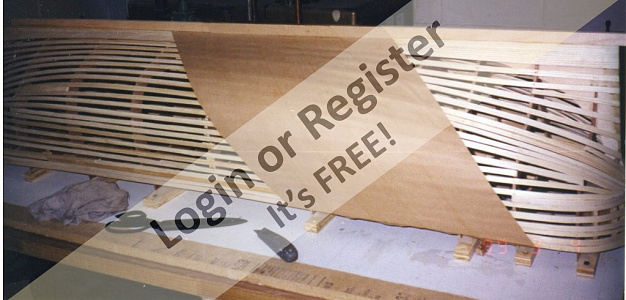
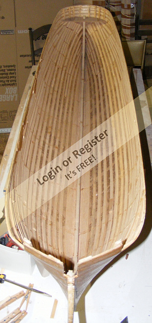
I got the idea of making a plug for a mold so I could turn out THREE hulls! One for me, one for sale, and one to be donated to the real ship. To that end, and with the inspiration of the book, instead of planking, I battened the hull and sheathed it with brown paper wet-n-stick packing tape.
Let's just say, that wasn't a good idea and leave it at that.
A lot of life changes happened; moved to a farm; got unmarried, sold the farm, got an apartment, got a house with a workshop, and 10 years later, recommenced work on the model.
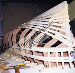
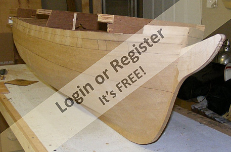
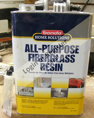
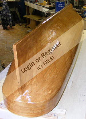
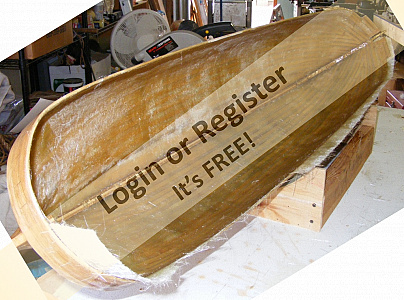
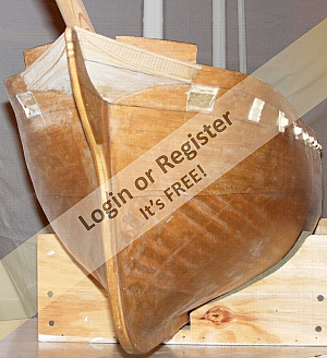
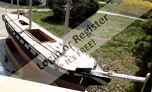
I continued on with the original plan for about a day when I shifted gears and decided to glass the "plug" and make it a hull. I proceeded to prep it to that end, but looking back, what I should have done was strip it down the the forms and start again, planking it properly. instead, I covered the outside with 4oz cloth, filled between the battens with poly resin and glass matting.
The images show the model from it's start to it's glassing, though the site won't allow me to dictate the order in which they're presented - sorry for that.
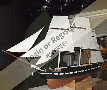
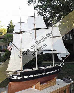
The model is of the American sloop of war Constellation launched in 1855, and as she appeared in Naples in 1856 based on a painting of her by Thomas deSimone.
She is 1:36 scale; 1 inch = 3 feet.
Beam: 13-5/8" (34.6 cm)
Length on deck: 61" (154.9 cm)
Length between perpendiculars (American): 59-1/8" (150.2 cm)
Draft, without ballast keel: 7" (17.8 cm) With 3-1/2" ballast keel: 10-1/2" (26.7 cm)
Weight, with ballast: Approx. 100 pounds (45.36 kg)
Length over the rig: 95" (241.3 cm)
Width over the rig: 30.5" (77.5 cm) ~ Main yard w/o stuns'l booms.
Height bottom of keel to main truck, without ballast keel: 65" (165.1 cm) With ballast keel: 69" (175.3 cm)
Total Sail Area: 2,807.01 square inches in 17 sails (19.5 sf, 18,110 scm, 1.8 sqm)
Working Sail Area: 1,836.1square inches in 13 sails (12.75 sf, 11,845 scm, 1.2 sqm)


It began as plywood paneling pulled from the walls of my first house and cut into frames. it was to be planked with white pine strips, also scraps from remodeling, but I was distracted by a book. Nasty things books, put all sorts of ideas in your head.
I got the idea of making a plug for a mold so I could turn out THREE hulls! One for me, one for sale, and one to be donated to the real ship. To that end, and with the inspiration of the book, instead of planking, I battened the hull and sheathed it with brown paper wet-n-stick packing tape.
Let's just say, that wasn't a good idea and leave it at that.
A lot of life changes happened; moved to a farm; got unmarried, sold the farm, got an apartment, got a house with a workshop, and 10 years later, recommenced work on the model.
I continued on with the original plan for about a day when I shifted gears and decided to glass the "plug" and make it a hull. I proceeded to prep it to that end, but looking back, what I should have done was strip it down the the forms and start again, planking it properly. instead, I covered the outside with 4oz cloth, filled between the battens with poly resin and glass matting.
The images show the model from it's start to it's glassing, though the site won't allow me to dictate the order in which they're presented - sorry for that.
The model is of the American sloop of war Constellation launched in 1855, and as she appeared in Naples in 1856 based on a painting of her by Thomas deSimone.
She is 1:36 scale; 1 inch = 3 feet.
Beam: 13-5/8" (34.6 cm)
Length on deck: 61" (154.9 cm)
Length between perpendiculars (American): 59-1/8" (150.2 cm)
Draft, without ballast keel: 7" (17.8 cm) With 3-1/2" ballast keel: 10-1/2" (26.7 cm)
Weight, with ballast: Approx. 100 pounds (45.36 kg)
Length over the rig: 95" (241.3 cm)
Width over the rig: 30.5" (77.5 cm) ~ Main yard w/o stuns'l booms.
Height bottom of keel to main truck, without ballast keel: 65" (165.1 cm) With ballast keel: 69" (175.3 cm)
Total Sail Area: 2,807.01 square inches in 17 sails (19.5 sf, 18,110 scm, 1.8 sqm)
Working Sail Area: 1,836.1square inches in 13 sails (12.75 sf, 11,845 scm, 1.2 sqm)
▲
⟩⟩
SelwynWilliams
Colin H
cenbeth
Dave M
Mataroa
teejay
RNinMunich
|
💬 Constellation
7 years ago by 🇬🇧 Dave M (
 Vice Admiral) Vice Admiral)✧ 81 Views · 0 Likes
Flag
Course not but we can expect some really good blogs judging by what you have posted so far
Dave ▲
⟩⟩
No likes yet
This member will receive 1 point for every like received |
|
Login To
Remove Ads 💬 Constellation
7 years ago by 🇺🇸 Jerry Todd (
Midshipman)✧ 82 Views · 1 Like
Flag
You can't expect me to post 18 years in one go! 😁
▲
⟩⟩
AllenA
|
|
💬 Constellation
7 years ago by 🇬🇧 Dave M (
Vice Admiral)✧ 81 Views · 0 Likes
Flag
For all its iterations the end result has remained true to the original and the model sails very realistically.
It would be good to see another post to the blog showing the electrics and another the sails. Dave ▲
⟩⟩
No likes yet
This member will receive 1 point for every like received |
Login To
Remove Ads
Remove Ads
📝 water, paint, copper
7 years ago by 🇺🇸 Jerry Todd ( Midshipman)
Midshipman)✧ 88 Views · 8 Likes · 1 Comment
Flag
💬 Add Comment
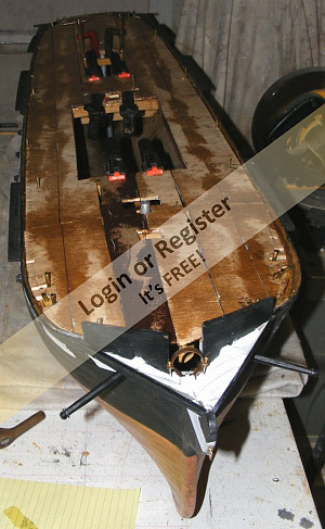
The gun deck isn't modeled. I was building a model intended to sail in open water and didn't want to deal with open gun ports, hatches, etc.
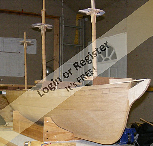
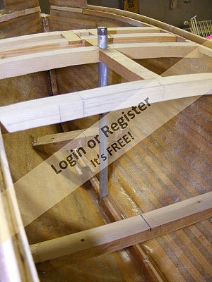
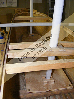
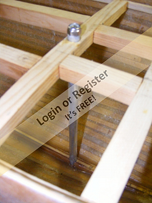
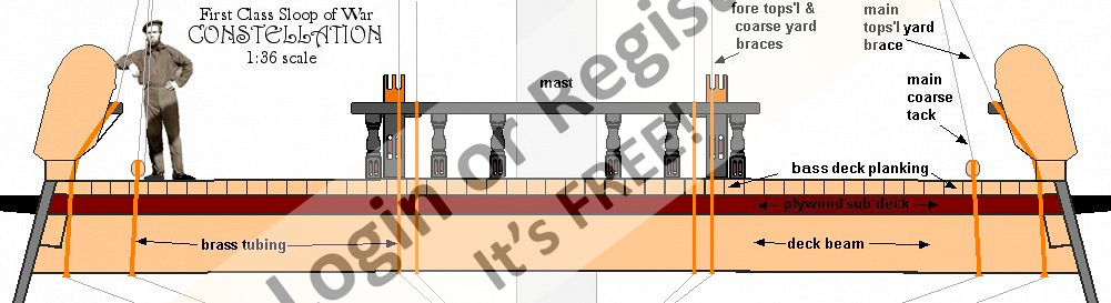
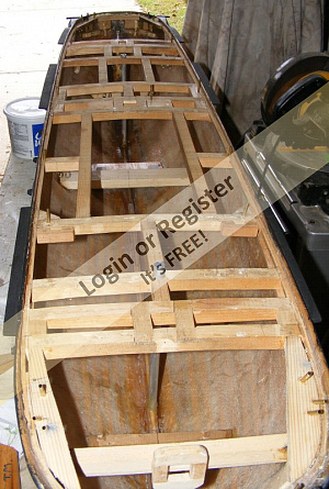
After glassing the hull, she got beams for the spar deck installed. 3/4" x 3/4", they're probably a bit more than was needed.
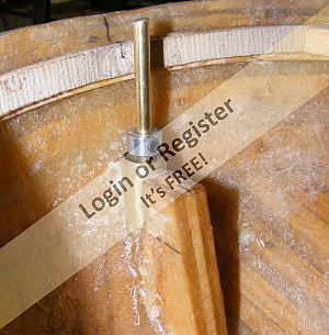
Tubes were installed for 5/16" stainless threaded rods that would hold her external ballast on. The forward one will be disguised as her galley stovepipe, the aft one is hidden under the cabin skylight. The ballast is a 2" i.d. PVC pipe about 4 feet long, filled with lead bird-shot, and weighing some 42 pounds.
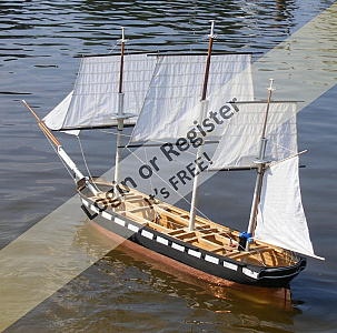
With that much done, I took her to the creek to see her float, but I forgot the rods. A few days later I took her out again, remembering the rods, and put her lower masts in her.
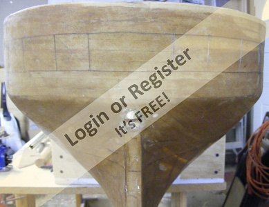
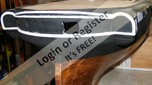
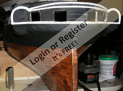
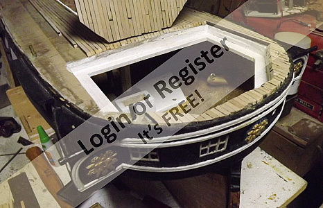
Now baptized, I applied the moldings and trim on her stern, and built up her enclosed head.
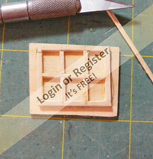
Her gunport were molded in resin in the closed position with the guns clamped in the openings and a tampion in the muzzles. These were epoxied into gunports cut from the outer layer of glass and wood battens, leaving the matting in place as a backer.
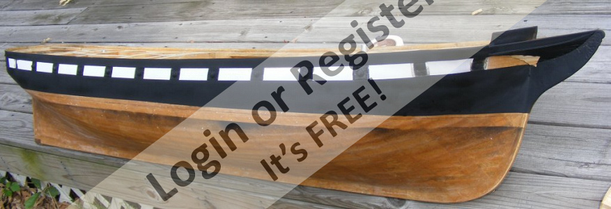
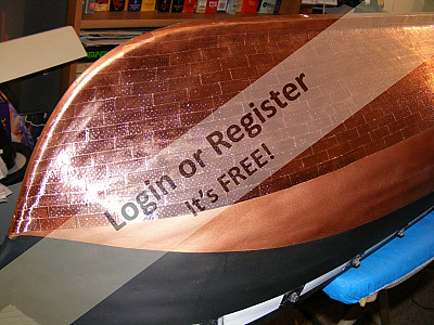
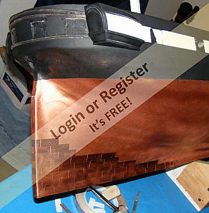
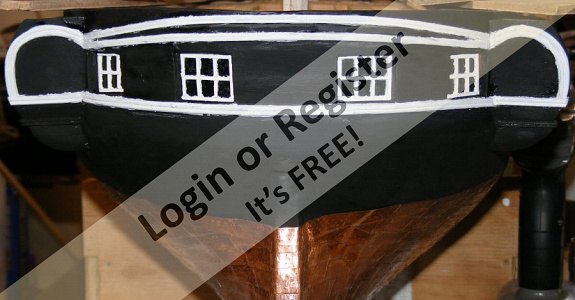
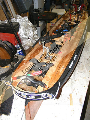
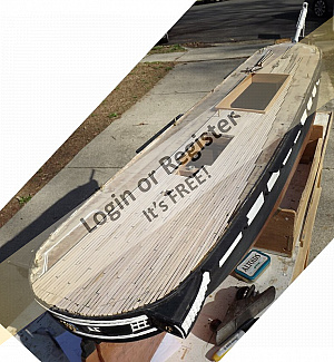
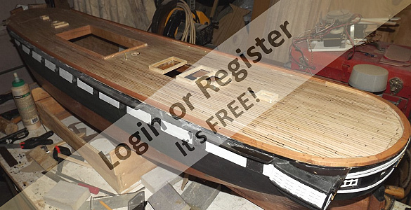
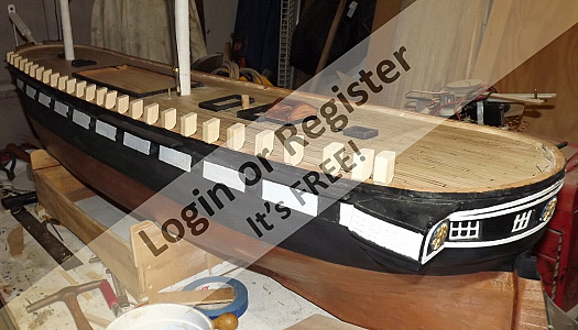
Then she got some paint, mainly because I was getting tired of her looking like a barkless log. The bottom was painted with copper paint, but three rolls of 1/2" wide peel-n-stick tape had just arrived and I started into coppering her bottom right off.
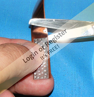
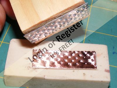
Copper plates are nailed on with copper nails with counter-sunk heads through pre-punched holes in the copper sheets. They are FLAT with with a little hollow where they're driven in just beyond flush with the surface. They are NOT round headed nor look like rivets as so many modelers insist are doing. I pressed an impression of the nails into the face of each plate. installing them pushes this dent back out and leaves a little circle that looks as it should.
It took about a week to do one side, and I took a break to make the tops for the lower masts, then continued onto coppering the other side. it was bright and beautiful when finished, but it wouldn't stay that way. Copper doesn't turn green when submerged, any copper coin will show you it turns brown. I wanted her bottom to brown somewhat, but not too much, and I figured to let that happen naturally. When it got where I wanted it, I'd clear-coat it to lock it in.
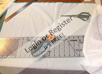
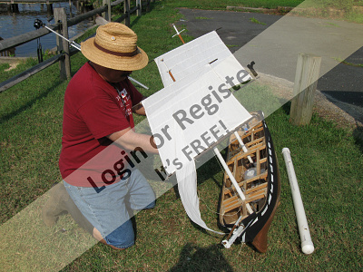
Two yards of Dupont Supplex cloth was ordered to make her sails. This is the stuff SC&H used on their square-rigger kits and it's great for making sails. Being a nylon, you cut it with a hot-knife, and use a pointed tip in a soldering iron to make grommets. I drew on the panel seams with a .03 marker as even the finest stitching is over scale even at 1:36. Top-cloths, corner reinforces, reef bands, etc, are all cut from the same cloth and glued on with fabric adhesive. The only sewing was of the bolt-ropes. These are done by hand much the way real ones are - I've sewn a few miles of real bolt ropes in my time. There's really no substitute for this if you want a functional scale appearing sail. A machine can't sew it properly, in the right position, or securely.


After glassing the hull, she got beams for the spar deck installed. 3/4" x 3/4", they're probably a bit more than was needed.
Tubes were installed for 5/16" stainless threaded rods that would hold her external ballast on. The forward one will be disguised as her galley stovepipe, the aft one is hidden under the cabin skylight. The ballast is a 2" i.d. PVC pipe about 4 feet long, filled with lead bird-shot, and weighing some 42 pounds.
With that much done, I took her to the creek to see her float, but I forgot the rods. A few days later I took her out again, remembering the rods, and put her lower masts in her.
Now baptized, I applied the moldings and trim on her stern, and built up her enclosed head.
Her gunport were molded in resin in the closed position with the guns clamped in the openings and a tampion in the muzzles. These were epoxied into gunports cut from the outer layer of glass and wood battens, leaving the matting in place as a backer.
Then she got some paint, mainly because I was getting tired of her looking like a barkless log. The bottom was painted with copper paint, but three rolls of 1/2" wide peel-n-stick tape had just arrived and I started into coppering her bottom right off.
Copper plates are nailed on with copper nails with counter-sunk heads through pre-punched holes in the copper sheets. They are FLAT with with a little hollow where they're driven in just beyond flush with the surface. They are NOT round headed nor look like rivets as so many modelers insist are doing. I pressed an impression of the nails into the face of each plate. installing them pushes this dent back out and leaves a little circle that looks as it should.
It took about a week to do one side, and I took a break to make the tops for the lower masts, then continued onto coppering the other side. it was bright and beautiful when finished, but it wouldn't stay that way. Copper doesn't turn green when submerged, any copper coin will show you it turns brown. I wanted her bottom to brown somewhat, but not too much, and I figured to let that happen naturally. When it got where I wanted it, I'd clear-coat it to lock it in.
Two yards of Dupont Supplex cloth was ordered to make her sails. This is the stuff SC&H used on their square-rigger kits and it's great for making sails. Being a nylon, you cut it with a hot-knife, and use a pointed tip in a soldering iron to make grommets. I drew on the panel seams with a .03 marker as even the finest stitching is over scale even at 1:36. Top-cloths, corner reinforces, reef bands, etc, are all cut from the same cloth and glued on with fabric adhesive. The only sewing was of the bolt-ropes. These are done by hand much the way real ones are - I've sewn a few miles of real bolt ropes in my time. There's really no substitute for this if you want a functional scale appearing sail. A machine can't sew it properly, in the right position, or securely.
▲
⟩⟩
Northumbrian
SelwynWilliams
Colin H
cenbeth
Dave M
Mataroa
Krampus
teejay
|
💬 water, paint, copper
7 years ago by 🇬🇧 Dave M (
Vice Admiral)✧ 83 Views · 1 Like
Flag
Some really good methods here. I am impressed with the copper plates. Where did you source the Peel-n-stick tape? is it a tool for making the impressions or did you make them all one by one?
The sail making is really enlightening. Were you involved in professionally making sails as you seem to have more than a passing knowlede? I am sure we will all benefit greatly from your shared knowledge. Dave ▲
⟩⟩
AllenA
|
📝 Masts, mast steps, inside the hull, the rudder
7 years ago by 🇺🇸 Jerry Todd ( Midshipman)
Midshipman)✧ 87 Views · 6 Likes
Flag
💬 Add Comment
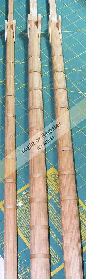
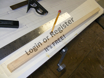
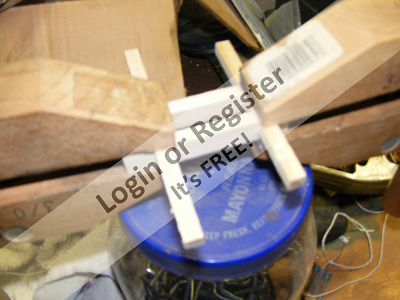
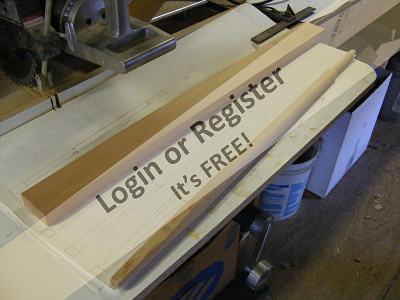
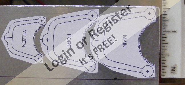
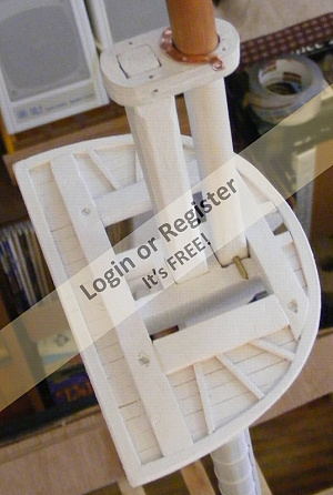
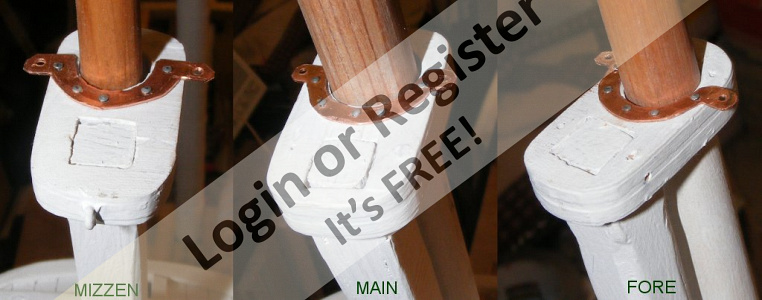
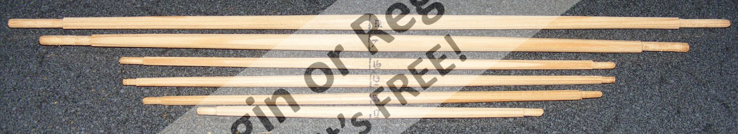
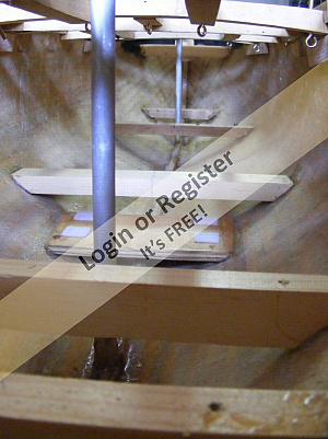
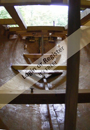
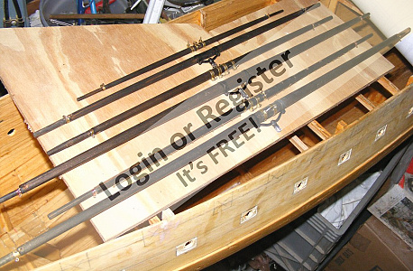
The model's lower masts are made of white cedar. These were cut square, a taper hand-planed in, made 8-sided, then round. The bands are the same brown paper tape the hull was covered in.
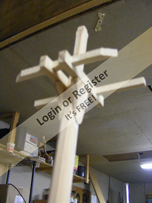
A visit to the real ship in Baltimore to get measurements, and look at some artifacts netted me some bits of live oak original to the ship. The Navy began stockpiling live oak for ship-building in 1816 with the Gradual increase Act. it was from these stockpiles that Constellation was built. These trees were as much as 200 years old when cut, so this wood I have could be as much as 400 years old. I wasn't sure how to incorporate this bit of the ship into the model, and opted to make the mast steps from it. One piece is the size of a business card and stamped USS Constellation 1854. I'll stamp the year she's finally finished and my name into that and install it as her builder's plate.
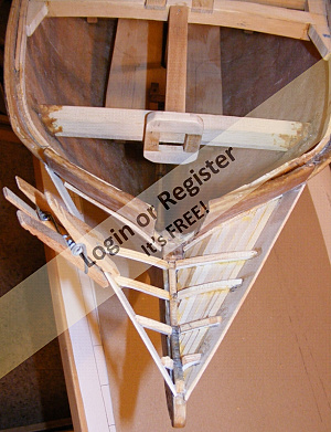
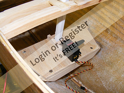
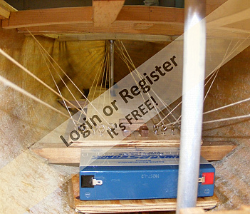
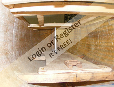
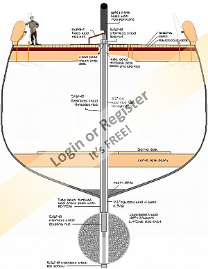
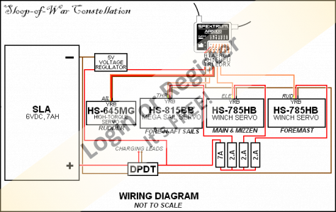
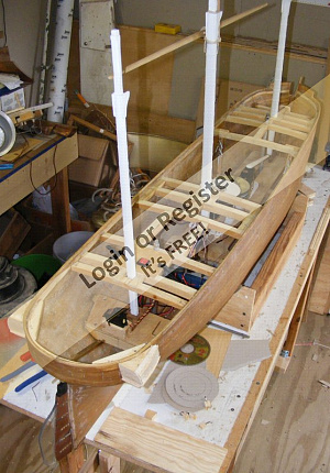
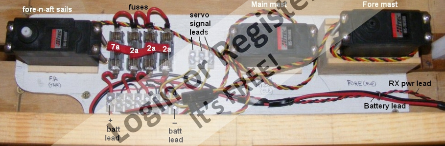
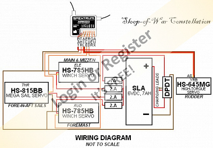
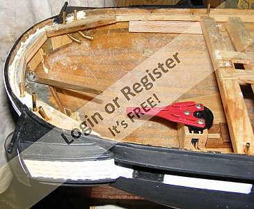
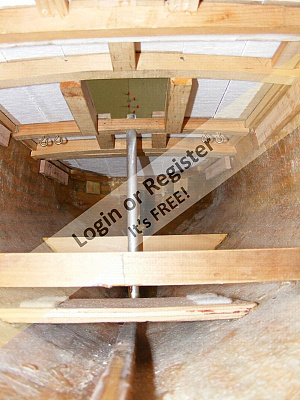
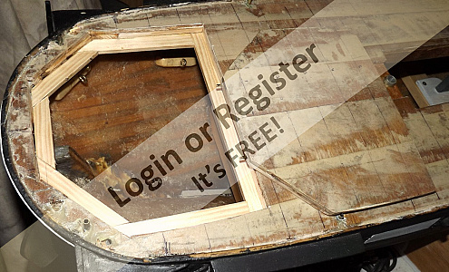
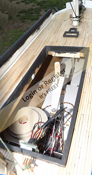
The masts step on what I call her mechanical decks. These are simple 3/8" plywood panels where her mechanics and controls will be mounted. Beams were epoxied into the hull for them, and they are held in place with brass wood screws. The aft deck is where the mizzen steps and the rudder servo is mounted. The battery lies on it's own deck just abaft the main mast as low as it can possibly be inside the hull.
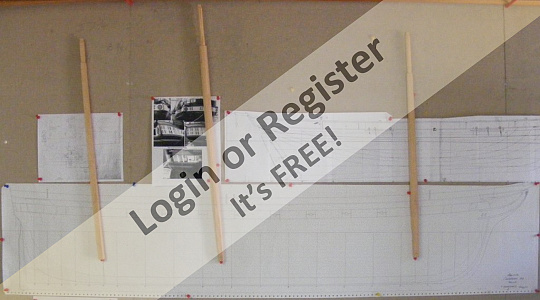
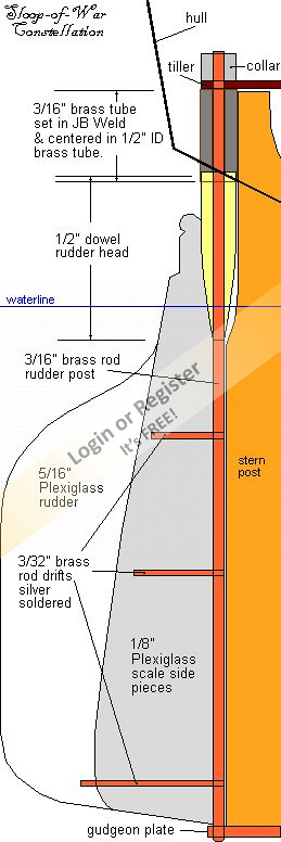
The cross-section drawing shows deck beams, decks, ballast rods, the external ballast, etc etc etc.
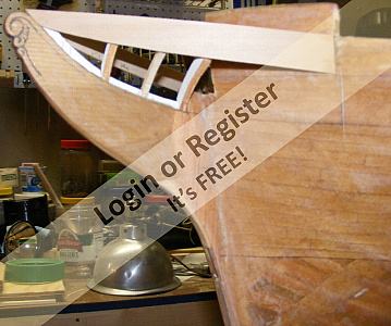
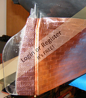
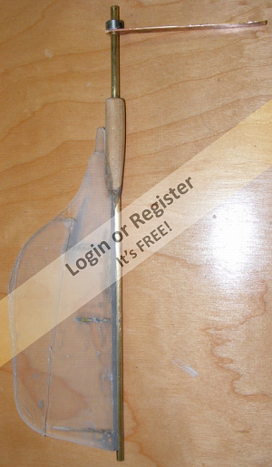
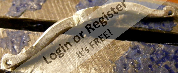
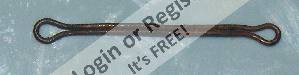
The rudder is made from Plexiglas as shown in it's drawing. A brass tube passes through the stern that the rudder's head just fits into. There's no room behind the rudder head for a bell-crank setup to work, so I again went with real boat tech and installed a tiller, made of copper plate soldiered to a set-collar.
There's a couple of pictures of the aluminum tubes for the ballast rods in there.
You may want to right-click on an image, like the drawings, and "View Image" then click on it to see it full size and legible. Use the browser's "back" button to get out of that.


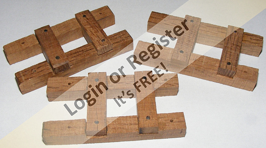


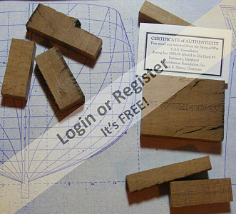
A visit to the real ship in Baltimore to get measurements, and look at some artifacts netted me some bits of live oak original to the ship. The Navy began stockpiling live oak for ship-building in 1816 with the Gradual increase Act. it was from these stockpiles that Constellation was built. These trees were as much as 200 years old when cut, so this wood I have could be as much as 400 years old. I wasn't sure how to incorporate this bit of the ship into the model, and opted to make the mast steps from it. One piece is the size of a business card and stamped USS Constellation 1854. I'll stamp the year she's finally finished and my name into that and install it as her builder's plate.
The masts step on what I call her mechanical decks. These are simple 3/8" plywood panels where her mechanics and controls will be mounted. Beams were epoxied into the hull for them, and they are held in place with brass wood screws. The aft deck is where the mizzen steps and the rudder servo is mounted. The battery lies on it's own deck just abaft the main mast as low as it can possibly be inside the hull.
The cross-section drawing shows deck beams, decks, ballast rods, the external ballast, etc etc etc.
The rudder is made from Plexiglas as shown in it's drawing. A brass tube passes through the stern that the rudder's head just fits into. There's no room behind the rudder head for a bell-crank setup to work, so I again went with real boat tech and installed a tiller, made of copper plate soldiered to a set-collar.
There's a couple of pictures of the aluminum tubes for the ballast rods in there.
You may want to right-click on an image, like the drawings, and "View Image" then click on it to see it full size and legible. Use the browser's "back" button to get out of that.
▲
⟩⟩
SelwynWilliams
Colin H
cenbeth
Dave M
RNinMunich
Mataroa
📝 Controls
7 years ago by 🇺🇸 Jerry Todd ( Midshipman)
Midshipman)✧ 86 Views · 5 Likes · 3 Comments
Flag
💬 Add Comment
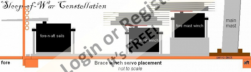
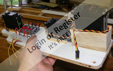
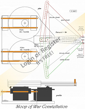
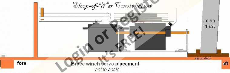
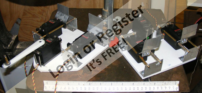
Initially, control of the sails, or rather the yards from which the sails hang, was going to be done with sail-winch servos; one for the yards of the foremast, another for the yards of the main and the mizzen mast combined.
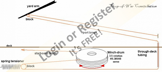
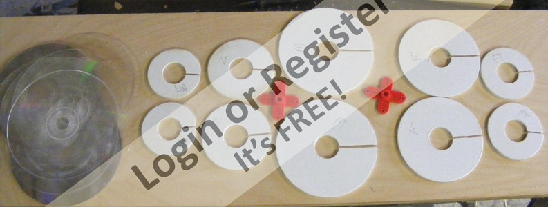
Each controlled yard would have two drums, one to take up it's braces as the other payed them out. The controlled yards would be the fore course and tops'l yards, the main course and tops'l yards, and the mizzen coss-jack. This meant the main/mizzen had 6 drums and the fore mast winch had 4. The drums diameter corresponded their yards as each brace was of a different length because of the distance from the centerline that the brace was attached to the yard. Since each brace was being controlled by one winch turning at the same speed, the difference had to be made up in the drum diameter. The flanges separating the drums were compact-discs (CDs).
The point where the brace attached to the yard describes part of a circle as the yard is turned. The winch drums too, are circles, but the brace from the yard to the point it turns down to the deck, is a vector. Because of this, both braces are tight when the yard is squared, but as it turns to one side, the take-up side stays taught while the paying out side goes slack. Slack on a winch drum is not a good thing, so some means of taking out any slack has to be devised. At this point I was going to mount springs on posts in the hull. They would maintain tension on the braces all the time.
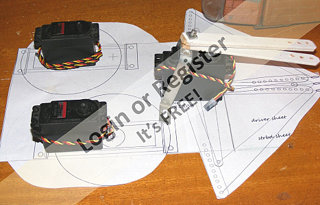
The two winches and a sail-arm servo that would control the heads'ls and driver, were all mounted on a tray, or pallet, that would be screwed to the mechanical deck. One winch had to be mounted higher than the other so the drums and braces wouldn't interfere.
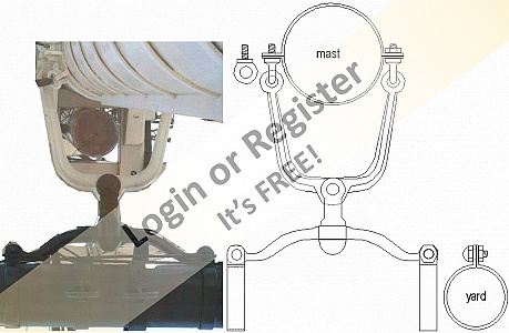
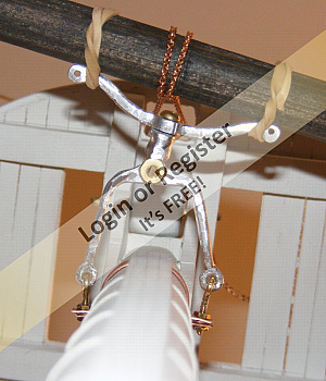
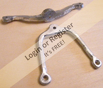
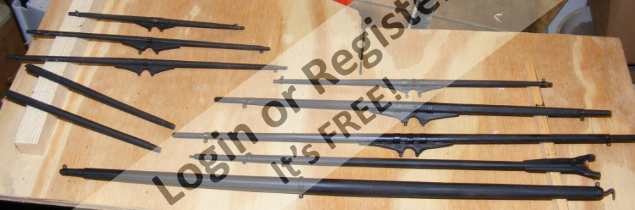
The real ship's yards were/are attached to the masts and pivoted on iron "patent trusses." I made my facsimile of them from aluminum with brass #2 screws, nuts, and eye-bolts I bent and threaded from brass rod. The clevis between the yard and the mast is 1/4" aluminum rod drilled through and shaped.


Each controlled yard would have two drums, one to take up it's braces as the other payed them out. The controlled yards would be the fore course and tops'l yards, the main course and tops'l yards, and the mizzen coss-jack. This meant the main/mizzen had 6 drums and the fore mast winch had 4. The drums diameter corresponded their yards as each brace was of a different length because of the distance from the centerline that the brace was attached to the yard. Since each brace was being controlled by one winch turning at the same speed, the difference had to be made up in the drum diameter. The flanges separating the drums were compact-discs (CDs).
The point where the brace attached to the yard describes part of a circle as the yard is turned. The winch drums too, are circles, but the brace from the yard to the point it turns down to the deck, is a vector. Because of this, both braces are tight when the yard is squared, but as it turns to one side, the take-up side stays taught while the paying out side goes slack. Slack on a winch drum is not a good thing, so some means of taking out any slack has to be devised. At this point I was going to mount springs on posts in the hull. They would maintain tension on the braces all the time.
The two winches and a sail-arm servo that would control the heads'ls and driver, were all mounted on a tray, or pallet, that would be screwed to the mechanical deck. One winch had to be mounted higher than the other so the drums and braces wouldn't interfere.
The real ship's yards were/are attached to the masts and pivoted on iron "patent trusses." I made my facsimile of them from aluminum with brass #2 screws, nuts, and eye-bolts I bent and threaded from brass rod. The clevis between the yard and the mast is 1/4" aluminum rod drilled through and shaped.
▲
⟩⟩
SelwynWilliams
cenbeth
Dave M
Colin H
figtree7nts
|
💬 Controls
7 years ago by 🇬🇧 Dave M (
Vice Admiral)✧ 83 Views · 0 Likes
Flag
Yes
Manufacturers seem to ignore the model boat fraternity. I use Taranis Tx as I can program it to do exactly what I want which is a boon with multiple servos to control. I do all the mixing on the Tx and output to the my chosen Rx channels from 1 Tx stick. I suspect you will have to make your own ratchets. The vertical sticks probably have all the bits but the horizontal will not. Have you considered using one of the knob controls? ▲
⟩⟩
No likes yet
This member will receive 1 point for every like received |
|
Login To
Remove Ads 💬 Controls
7 years ago by 🇺🇸 Jerry Todd (
Midshipman)✧ 83 Views · 0 Likes
Flag
The biggest pain in sailing her is the Dx6 transmitter, or any transmitter of that sort. I only wanted self-centering on the rudder, everything else I wanted ratcheted so it would stay where I put it, but the only channel with a ratchet was the throttle. I took off the self-centering springs where I didn't want them, but there's no easy way to ratchet them, and they move if you breathe on them.
Spektrum doesn't know for boat, or care for boaters, especially sail boaters. They sent me a contest entry questionnaire and the very first question was; "Do you use your radio for Helicopters, planes, or cars?" None of the above wasn't an option. ▲
⟩⟩
No likes yet
This member will receive 1 point for every like received |
|
💬 Controls
7 years ago by 🇬🇧 Dave M (
Vice Admiral)✧ 83 Views · 1 Like
Flag
Very impressive and authentic. it must take a whole heap of concentration to operate the sail controls.
▲
⟩⟩
Jerry Todd
|
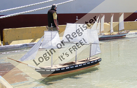
📝 Sailing for the First Time
7 years ago by 🇺🇸 Jerry Todd ( Midshipman)
Midshipman)✧ 89 Views · 5 Likes
Flag
💬 Add Comment
In April 2011 I set a deadline to sail the model for the first time on July 10th. I had places to go and other things to get done, so I figured that was far enough ahead to have her ready in time. There were a lot of things that needed to get done if the model was going to sail;
* Shape the still rough cut yards; fore course, fore tops'l, crossjack, and mizzen tops'l yards.
* Complete the yard trusses with mast bands and banding to attach them to the yards
* A gammon "iron" for the bowsprit.
* Rudder control & steering.
* New winch drum for braces (the originals with wood drums warped badly).
* Sails for planned sailing suit; 3 tops'ls, spanker, and jib.
She was basically jury-rigged, with all three course yards linked together to a single winch.
July 9th's forcaste was for perfect weather, light northerly wind, blowing up the creek so if there was a problem, the model would drift back to me. Unfortunately, I wasn't ready by the 9th and the 10th was light, variable, fluky, 90°, and humid.
The top mast fids were pulled and the topmasts lowered. The model with some tools, her ballast, and what I thought I might need were all placed in the truck the night before. The radio and main batter were put on charge.
Next day we drove the couple of block down the street to the Sloop Cove public dock on Stoney Creek. The rig was raised, ballast attached, electronics connected and tested, and she went into the water. With her ballast and extra lead I had she still sat 2" high in the water.
I set her out, but the iffy light wind sent he back, then she threatened to get tangled with a powerboat on a lift until I managed to squeek her out into open water.
She sailed a bit, but just when she'd get moving the wind would shift or reflect off something and catch her aback. Then suddenly she stopped responding at all. Something of a gust caught her and she headed for a dock. I headed over, which meant swimming, and not being a great swimmer realized I should have brought my flotation vest from my sailboat along. it being so hot, the swim wasn't exactly unwelcome, but it was a lot of work.
The model sailed right into the end of a dock about 100 feet away, bounced on her forestay, and basically parked there. I got her back to shore looking like a drowned cat myself, but there was no damage at all to the model. As it turned out, the main battery failed.
▲
⟩⟩
SelwynWilliams
none
Dave M
RNinMunich
figtree7nts
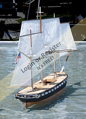
📝 Changes in latitudes
7 years ago by 🇺🇸 Jerry Todd ( Midshipman)
Midshipman)✧ 86 Views · 3 Likes · 1 Comment
Flag
💬 Add Comment
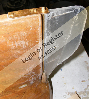
After the sail I tried to figure out how to make the chain plates. The links below the channel are easy enough, but the doubled rod strap that wraps the deadeye was (and is) giving me headaches.
I was originally going to bolt the chainplates to the hull, but instead I intend to use round-headed brass wood screws, and I've installed oak strips inside the hull to give them something to bite into.
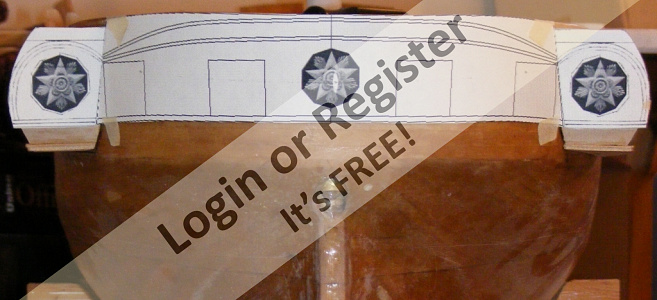
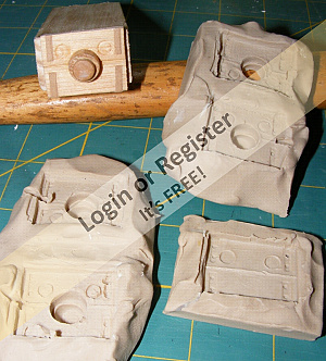
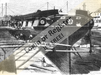
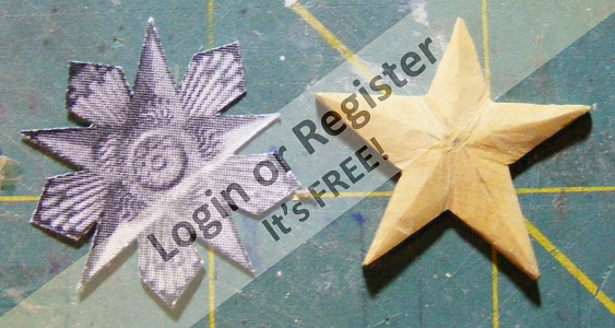
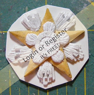
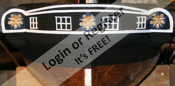
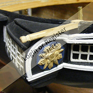
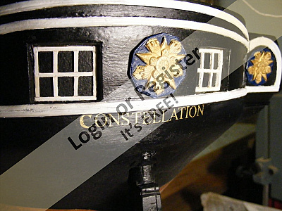
You may recall I'm modeling the ship as she was new, when her portrait was painted in 1856. There's nearly nothing showing what her stern looked like but one etching done of her in dry-dock in Boston in 1859 when she returned from her first cruise. Several painting of her contemporaries show very similar stern ornamentation. I already had the moldings applied based on the drydock drawing, now I made the three rosettes she still carries today - her "constellation of stars."
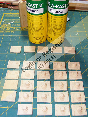
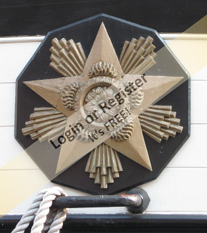
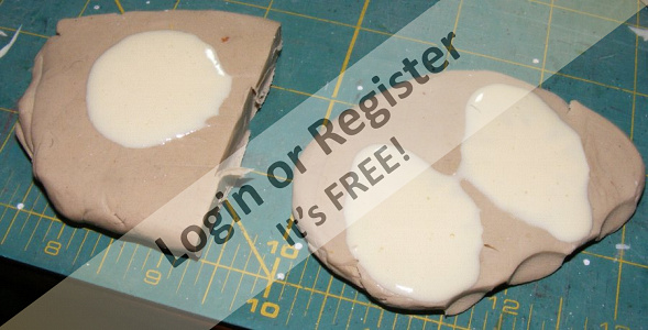
My first attempt was too think and bulky, so I started fresh with a bit of boxwood, and used styrene to apply details. Once done, it got a coat of primer and then I pressed it into clay to make molds for the casting resin. if I had a "Constellation Restaurant" my butter pads would all be molded like this 😊
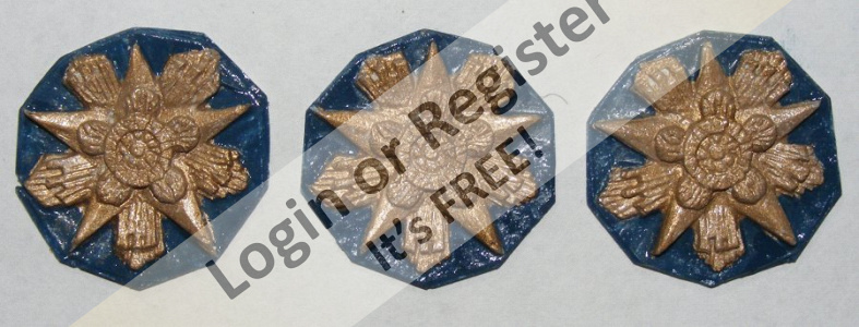
Checking into the fashion of the day for depicting stars and things astronomical, I painted the stars gold on a royal blue background. They were then epoxied to the hull and quarter galleries.
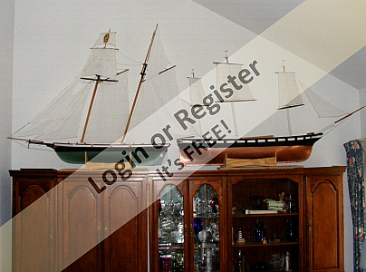
Soon after, I lost my job of 18 years, and about a year later had to move out of the house and in with my girlfriend. The models literally went on the shelf.
She sat on top of a cabinet for nearly a year when I got an invite from the director of Historic Ships Baltimore to bring the model to the Baltimore Port Expo celebrating National Maritime Day.
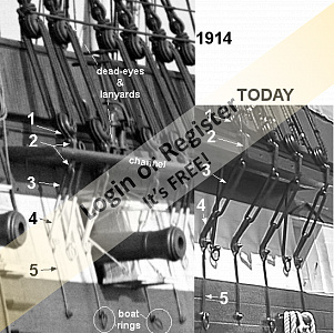


I was originally going to bolt the chainplates to the hull, but instead I intend to use round-headed brass wood screws, and I've installed oak strips inside the hull to give them something to bite into.
You may recall I'm modeling the ship as she was new, when her portrait was painted in 1856. There's nearly nothing showing what her stern looked like but one etching done of her in dry-dock in Boston in 1859 when she returned from her first cruise. Several painting of her contemporaries show very similar stern ornamentation. I already had the moldings applied based on the drydock drawing, now I made the three rosettes she still carries today - her "constellation of stars."
My first attempt was too think and bulky, so I started fresh with a bit of boxwood, and used styrene to apply details. Once done, it got a coat of primer and then I pressed it into clay to make molds for the casting resin. if I had a "Constellation Restaurant" my butter pads would all be molded like this 😊
Checking into the fashion of the day for depicting stars and things astronomical, I painted the stars gold on a royal blue background. They were then epoxied to the hull and quarter galleries.
Soon after, I lost my job of 18 years, and about a year later had to move out of the house and in with my girlfriend. The models literally went on the shelf.
She sat on top of a cabinet for nearly a year when I got an invite from the director of Historic Ships Baltimore to bring the model to the Baltimore Port Expo celebrating National Maritime Day.
▲
⟩⟩
SelwynWilliams
cenbeth
Dave M
|
💬 Changes in latitudes
7 years ago by 🇬🇧 Dave M (
Vice Admiral)✧ 85 Views · 1 Like
Flag
Great detail on the chainplates. The castings have made the model so authentic.
▲
⟩⟩
figtree7nts
|
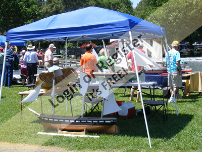
📝 On Public Display
7 years ago by 🇺🇸 Jerry Todd ( Midshipman)
Midshipman)✧ 86 Views · 2 Likes
Flag
💬 Add Comment
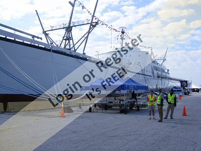
This would be the first time I ever put something on public display. Well, some drawings went up in a high school art show, but this was certainly the first model.
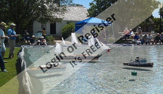
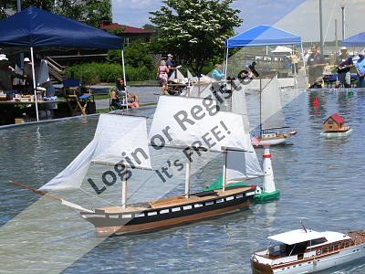
The Port Expo had set up a pool on the dock next to the N.S. Savannah. it was windy, with the wind whipping around the ship every which way. The pool wasn't deep enough for the model to sail, so she just sat there tied off to one end, or down in the lee corner. Not a big deal, but I got to talk to a few folks about her, and that was fun.
One of the other modelers told me about the model expo at the Chesapeake Bay Maritime Museum in St Michaels Maryland, in just two weeks! Last time I had been to that museum I went on a 170 foot barkentine, this time the boat would be a little smaller.
There was no way I was going to get much work done on the model in the time I had, but there was something I wanted to try out.
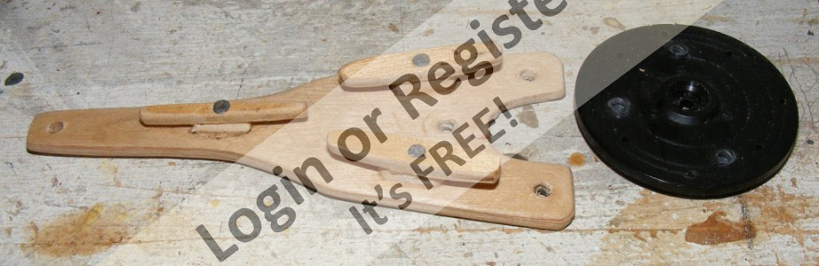
From the start I had a sail-arm servo set-up to handle the fore-and-aft sails, but I hadn't worked out how it would work. The heads'ls over-lapped and each had two sheets. When the model come-about, the heads'ls needed to be hauled over the stays to the other side.
When sailing a real boat, like my 16 footer 'Lydia,' it's the same thing. When you start to come about, you cast-off the jib sheet. As the boat comes across the wind, the jib luffs and comes across mostly on it own. The the new sheet is hauled in and made fast. I wanted to emulate that on the model. My solution was two loose arms with the servo arm between them. The servo pushes one or the other of the loose arms to sheet the heads'ls - but not both. Center the servo and both jib-sheets are slack.
It's incredibly simple and works on a single servo.
I cobbled the system together in time for St Michaels. We also got one of those pop-up tents, and a folding table. I was taking the Pride of Baltimore model, and the Macedonian hull as well. I was getting into this public display thing.
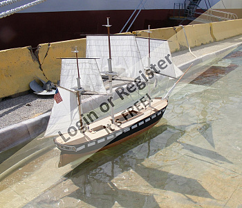
The Model Expo was great. There were a boat-load of modeler's and model there. The pool was much larger, but it was still too shallow, and Stella ran aground after sailing only a few feet.
Only Constellation went in the water, but all three models got a lot of attention and I spent a lot of time talking to folks about them.
The jib-sheeter worked great, though the servo only had 90° of travel and the Dx6 isn't programmable that way.
When I got home, I went right to work on another control mechanism I wanted to try - the sliding-winch.


The Port Expo had set up a pool on the dock next to the N.S. Savannah. it was windy, with the wind whipping around the ship every which way. The pool wasn't deep enough for the model to sail, so she just sat there tied off to one end, or down in the lee corner. Not a big deal, but I got to talk to a few folks about her, and that was fun.
One of the other modelers told me about the model expo at the Chesapeake Bay Maritime Museum in St Michaels Maryland, in just two weeks! Last time I had been to that museum I went on a 170 foot barkentine, this time the boat would be a little smaller.
There was no way I was going to get much work done on the model in the time I had, but there was something I wanted to try out.
From the start I had a sail-arm servo set-up to handle the fore-and-aft sails, but I hadn't worked out how it would work. The heads'ls over-lapped and each had two sheets. When the model come-about, the heads'ls needed to be hauled over the stays to the other side.
When sailing a real boat, like my 16 footer 'Lydia,' it's the same thing. When you start to come about, you cast-off the jib sheet. As the boat comes across the wind, the jib luffs and comes across mostly on it own. The the new sheet is hauled in and made fast. I wanted to emulate that on the model. My solution was two loose arms with the servo arm between them. The servo pushes one or the other of the loose arms to sheet the heads'ls - but not both. Center the servo and both jib-sheets are slack.
It's incredibly simple and works on a single servo.
I cobbled the system together in time for St Michaels. We also got one of those pop-up tents, and a folding table. I was taking the Pride of Baltimore model, and the Macedonian hull as well. I was getting into this public display thing.
The Model Expo was great. There were a boat-load of modeler's and model there. The pool was much larger, but it was still too shallow, and Stella ran aground after sailing only a few feet.
Only Constellation went in the water, but all three models got a lot of attention and I spent a lot of time talking to folks about them.
The jib-sheeter worked great, though the servo only had 90° of travel and the Dx6 isn't programmable that way.
When I got home, I went right to work on another control mechanism I wanted to try - the sliding-winch.
▲
⟩⟩
SelwynWilliams
RNinMunich
📝 New Brace System
7 years ago by 🇺🇸 Jerry Todd ( Midshipman)
Midshipman)✧ 88 Views · 4 Likes · 2 Comments
Flag
💬 Add Comment
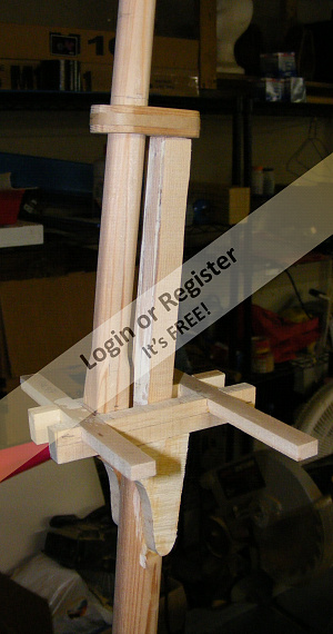
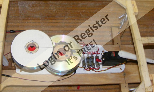
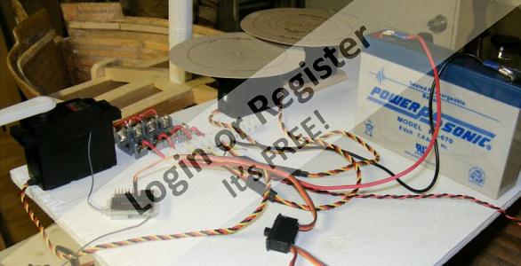
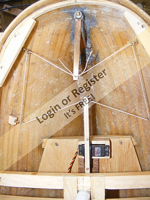
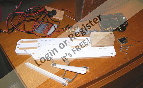
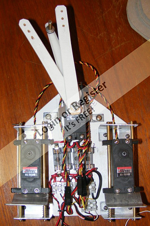
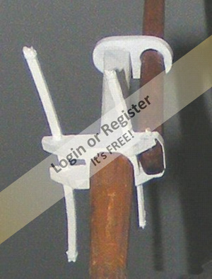
I've kept a log of this build on RCGroups forums since 2009. We share experiences, brainstorm ideas, and help each other out with a lot of the idiosyncrasies of RC square-rig sailing. A fellow there named Dan and I had a long running discussion on dealing with slack in the braces when there are prototypically mounted near the ends of the yards. This discussion led to the sliding winch. The winch servo, unaltered in any way, is mounted on Delrin blocks with holes through which pass a pair of brass rods. The winch can slide fore and aft on theses rods. A pair of aluminum angle hold the ends of the rods so the servo is off the deck and can move freely. A pair of spring are on the rods to provide tension by pushing against the winch.
When the yard is square across the model, the servo is pressing on the spring(s). As the yard is turned, the spring pushes the winch back on the rods taking up any slack in the braces.
I mounted everything on a pallet again, keeping it modular so I can get at things, and easily take them out if need be.
While assembling it, one of the winches started acting strange. I replaced it with another one, which required, removing the winch drum screw and drum; unplugging the servo from the receiver; loosening 4 screws that hold the winch to the slide-blocks; then do all that in reverse to put in the new winch.
I also got Servo-Stretchers that increase the the sail-arm servo's range from 90° to 180° and allow adjustment of the center position.
You'll notice two servo-trays in the pictures; the other one is for the Macedonian frigate model.
As the year went on, I installed bumpkins for and aft. Got some gold dry-transfer lettering and put her name on her stern. Made t'gallant/royal masts.Made a servo arm for the rudder servo that had cleats to allow steering cable adjustment. And installed fairleads for the running rigging below.
All things that had to get done in order to put the spardeck on.
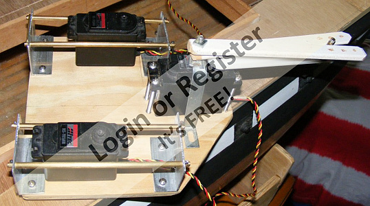
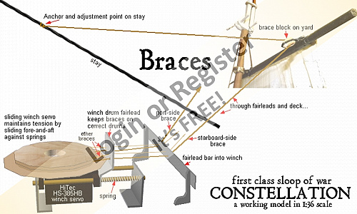
▲
⟩⟩
doghouse
SelwynWilliams
John2
cenbeth
|
💬 New Brace System
7 years ago by 🇺🇸 Jerry Todd (
Midshipman)✧ 87 Views · 2 Likes
Flag
When the yards are squared, the springs are compressed. I use springs that are just strong enough to push out the slack, not make bracing a battle between winch and springs.
You can see how it works here: 
▲
⟩⟩
Krampus
figtree7nts
|
|
💬 New Brace System
7 years ago by 🇬🇧 Dave M (
Vice Admiral)✧ 85 Views · 0 Likes
Flag
Ingenious method of taking up the slack. Does the spring place a constant load n the servo?
Dave ▲
⟩⟩
No likes yet
This member will receive 1 point for every like received |
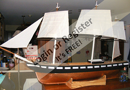
📝 The Spar Deck
7 years ago by 🇺🇸 Jerry Todd ( Midshipman)
Midshipman)✧ 91 Views · 6 Likes
Flag
💬 Add Comment
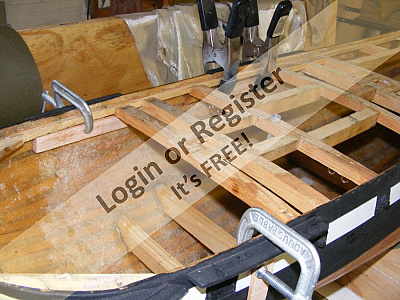
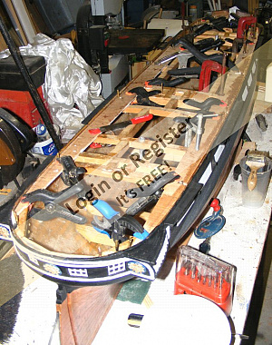
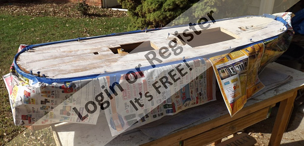
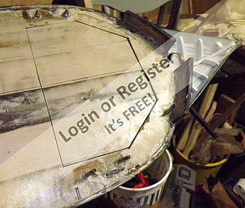
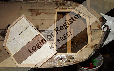
Once I was satisfied I had all the fairleads I needed, or might need (I put in some extras, just-in-case), it was time to permanently close up the deck.
The luan plywood sub-deck had long ago been cut into 2" strips to allow it to take the deck camber and sheer. I had also painted on it's underside except where the deck framing was, so the paint wouldn't interfere with the epoxy.
I got a few very nice days in October (2014) great for dealing with epoxy, and to take on this major step in the model's construction. There's a sinking feeling about this, like you've just locked your keys in the car.
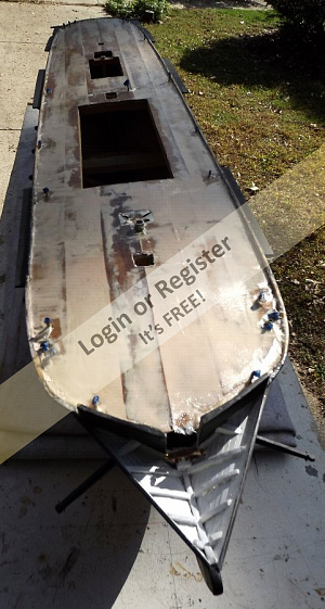
First I removed the mechanical decks below, cleaned out the hull, replaced a deck beam whose joint had never set right, and dabbed epoxy onto things I'd never be able to reach again. The mechanical decks were painted white. The turning blocks for the steering were epoxied in place; having been hot-glued in all these years.
Now I painted epoxy on the entire underside of each strip to seal it as well as glue it to the deck beams. Working from out-board toward the center-line. I clamped the strips down, but also used copper tacks to hold it down that would be left in. in short order, the sub-deck was epoxied and nailed in place. Now the only access inside was through the hatches.
All the cracks and seams on the deck were filled with polyester putty (Bondo), especially around the deck/hull joint. When this set, I sanded it, filled missed places, and sanded some more. Then a layer of 4oz cloth, left over from glassing her hull 5 years before, was laid on the sub-deck. At this point the deck was an integral part of the hull.
I ordered 3/16" x 48" square bass strips to plank the spar deck. I was going to cut this from a maple board I hand, but could get what I wanted safely from the saw. I was concerned bass (lime) wouldn't be hard enough, but it's been great.
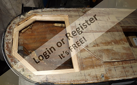
As holidays and cold weather reduced the time I could spend in the shop, I made up the rest of her spars and their hardware; as well as framing up and installing the fore and aft access hatches.
I also cut the deck strips to their length. Then winter came and stayed until April.
Meanwhile I hemmed the rest of her sails.


The luan plywood sub-deck had long ago been cut into 2" strips to allow it to take the deck camber and sheer. I had also painted on it's underside except where the deck framing was, so the paint wouldn't interfere with the epoxy.
I got a few very nice days in October (2014) great for dealing with epoxy, and to take on this major step in the model's construction. There's a sinking feeling about this, like you've just locked your keys in the car.
First I removed the mechanical decks below, cleaned out the hull, replaced a deck beam whose joint had never set right, and dabbed epoxy onto things I'd never be able to reach again. The mechanical decks were painted white. The turning blocks for the steering were epoxied in place; having been hot-glued in all these years.
Now I painted epoxy on the entire underside of each strip to seal it as well as glue it to the deck beams. Working from out-board toward the center-line. I clamped the strips down, but also used copper tacks to hold it down that would be left in. in short order, the sub-deck was epoxied and nailed in place. Now the only access inside was through the hatches.
All the cracks and seams on the deck were filled with polyester putty (Bondo), especially around the deck/hull joint. When this set, I sanded it, filled missed places, and sanded some more. Then a layer of 4oz cloth, left over from glassing her hull 5 years before, was laid on the sub-deck. At this point the deck was an integral part of the hull.
I ordered 3/16" x 48" square bass strips to plank the spar deck. I was going to cut this from a maple board I hand, but could get what I wanted safely from the saw. I was concerned bass (lime) wouldn't be hard enough, but it's been great.
As holidays and cold weather reduced the time I could spend in the shop, I made up the rest of her spars and their hardware; as well as framing up and installing the fore and aft access hatches.
I also cut the deck strips to their length. Then winter came and stayed until April.
Meanwhile I hemmed the rest of her sails.
▲
⟩⟩
doghouse
SelwynWilliams
John2
RNinMunich
figtree7nts
Krampus
📝 Building a deck
7 years ago by 🇺🇸 Jerry Todd ( Midshipman)
Midshipman)✧ 91 Views · 7 Likes
Flag
💬 Add Comment
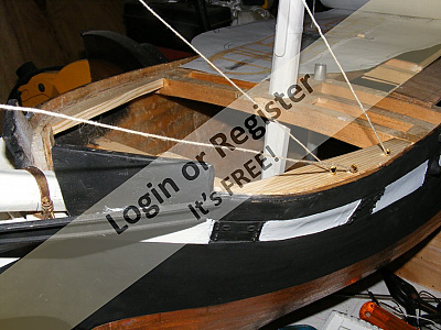
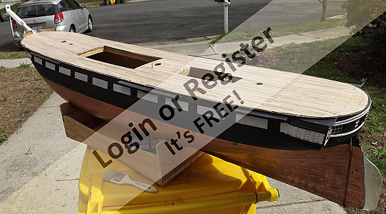
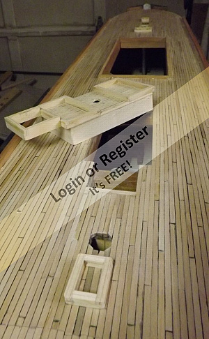
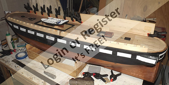
I began laying the deck on April 5th. it had snowed as recently as the week before, but it finally warmed up enough to use glue.
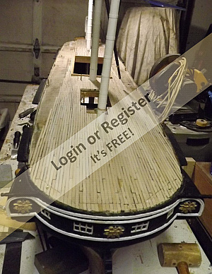
The strips were cut to 6-5/8" length, about 20' in 1:36 scale. I used a black marker on two opposite sides to represent the pitch in the seams. The deck was laid in a 5-plank pattern to mix up the butt-joints as much as I could. My research on her decking found she's had various styles and plank widths over her life. The earliest photo showing her deck that I could find, showed it straight planked with 7 or 8" wide boards based on the number of planks between her waterway and the main hatch coaming. Her waterway logs seem to be placed ON the decking, as there's no margin planks or joggling - even today.
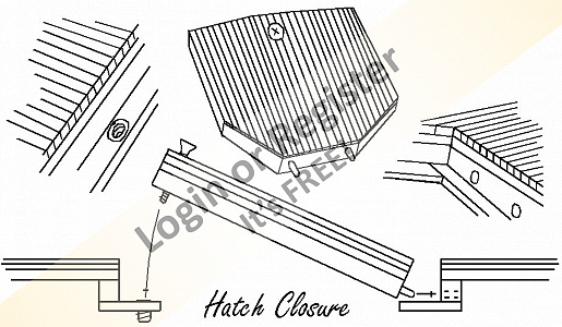
The planking was set with gel CA. Gorilla sells it in a nice bottle with a metal pin in the cap to keep the spout open. it would up taking 3 of these bottles to complete the deck. The planks are cut at a 45 on the ends along the fore and aft access hatches, to try and hide this seam as much as possible.
Once the deck was down, I scraped it. The glue is more resistant than the basswood is, so sanding would have scalloped the wood between seams. Scraping makes everything level. Some lite sanding, more to polish than remove anything, was done last.
I had planned to stain the deck a very light grayish tint, but an active naval vessel gets holy-stoned regularly and wouldn't be gray as the ships that sit at a dock today are.
In all it took 455 pieces to complete the deck and there wasn't any scrap longer than 1 inch left over. in all I have 3/4" deck beams, 1/4" plywood, a layer of 4oz cloth and resin, and a 3/16" basswood deck - I don't recall why I designed it so heavy, but it certainly doesn't hurt the model at all, and I think the 3/16" square strip will prove to have been easier to set than the 1/16" x 1/4" planks Pride and Macedonian will get.
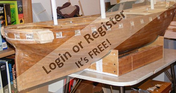
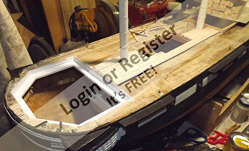
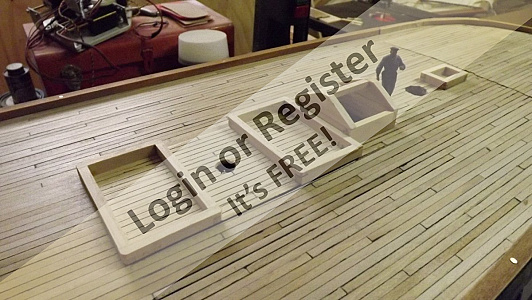
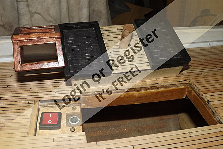
The deck go a coat of water-based satin poly, and I stared working on hatch coamings, cap log, and waterways. The cabin skylight and two hatched forward of it, including the capstan, and all combined into one hatch where the battery is accessed, and which hides the aft ballast rod and main power switch.
The cap logs Are 1/2" wide x 1/4" tall basswood that was tren'led, glued, and copper nailed, onto the deck, flush with the outside of the hull covering this seam completely. The the angled wood waterways were installed around the inside of the cap log, and the deck got a coat of oil-based satin poly. This actually leeched in and made the marker seams bleed a little. in hind sight, I think I'll go with paint over marker for seams in the future.
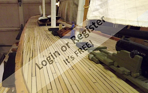
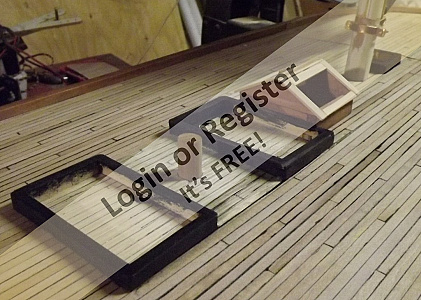
The coamings got painted black. I'm not sure why the Navy painted deck fittings black. it was even common to paint to top surfaces of tops black. I wonder how many injuries and losses this cost the navy that white paint would have prevented. Anyway...
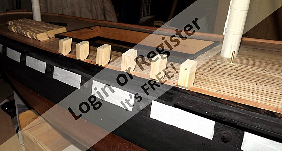
Constellation didn't have "solid" bulwarks, but rather she had hammock irons bolted to her cap log. These were removed when Baltimore tried to pass her off as a frigate and tossed in the bilge. When the ship was restored as a sloop of war, they found all but one. These irons are designed to have wooden rails at their tops, inboard and out, and have holes so several lines can be run through them. The Navy in it's wisdom though, decided to wainscot them to appear as solid bulwarks, despite the additional splinter hazard that would be in battle.
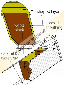
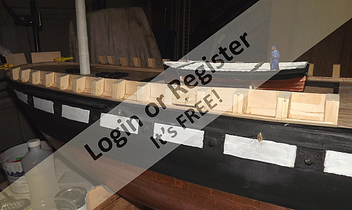
I wasn't making all those metal stanchions just to hide them under wood and tarps, so I made wood blocks sheathed in sheet bass, scribed to look like vertical wainscotting.
It was the end of April by now, and the Baltimore Port Expo was in two weeks. I wanted to have hammocks in the bulwarks, as she appears in the portrait, but there was no time to figure this out, so I layered on some balsa and shaped it so it looked like tarps were laid over the hammocks. When I figure out how I'll represent the stowed hammocks, I can pull the balsa off easily enough.
The bulwarks on, I made some fittings for the spencer masts; installed the eye bolts at the base of the masts; made some bollards (or whatever name they gave those posts), made and installed the catheads, which are laminated 1/16" basswood.
I then started setting up a jury rig and her controls so she could sail at the Port Expo. I set her t'gallants and all three heads'ls this time around. By the night before the Expo, she was ready to go.


The strips were cut to 6-5/8" length, about 20' in 1:36 scale. I used a black marker on two opposite sides to represent the pitch in the seams. The deck was laid in a 5-plank pattern to mix up the butt-joints as much as I could. My research on her decking found she's had various styles and plank widths over her life. The earliest photo showing her deck that I could find, showed it straight planked with 7 or 8" wide boards based on the number of planks between her waterway and the main hatch coaming. Her waterway logs seem to be placed ON the decking, as there's no margin planks or joggling - even today.
The planking was set with gel CA. Gorilla sells it in a nice bottle with a metal pin in the cap to keep the spout open. it would up taking 3 of these bottles to complete the deck. The planks are cut at a 45 on the ends along the fore and aft access hatches, to try and hide this seam as much as possible.
Once the deck was down, I scraped it. The glue is more resistant than the basswood is, so sanding would have scalloped the wood between seams. Scraping makes everything level. Some lite sanding, more to polish than remove anything, was done last.
I had planned to stain the deck a very light grayish tint, but an active naval vessel gets holy-stoned regularly and wouldn't be gray as the ships that sit at a dock today are.
In all it took 455 pieces to complete the deck and there wasn't any scrap longer than 1 inch left over. in all I have 3/4" deck beams, 1/4" plywood, a layer of 4oz cloth and resin, and a 3/16" basswood deck - I don't recall why I designed it so heavy, but it certainly doesn't hurt the model at all, and I think the 3/16" square strip will prove to have been easier to set than the 1/16" x 1/4" planks Pride and Macedonian will get.
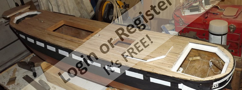
The deck go a coat of water-based satin poly, and I stared working on hatch coamings, cap log, and waterways. The cabin skylight and two hatched forward of it, including the capstan, and all combined into one hatch where the battery is accessed, and which hides the aft ballast rod and main power switch.
The cap logs Are 1/2" wide x 1/4" tall basswood that was tren'led, glued, and copper nailed, onto the deck, flush with the outside of the hull covering this seam completely. The the angled wood waterways were installed around the inside of the cap log, and the deck got a coat of oil-based satin poly. This actually leeched in and made the marker seams bleed a little. in hind sight, I think I'll go with paint over marker for seams in the future.
The coamings got painted black. I'm not sure why the Navy painted deck fittings black. it was even common to paint to top surfaces of tops black. I wonder how many injuries and losses this cost the navy that white paint would have prevented. Anyway...
Constellation didn't have "solid" bulwarks, but rather she had hammock irons bolted to her cap log. These were removed when Baltimore tried to pass her off as a frigate and tossed in the bilge. When the ship was restored as a sloop of war, they found all but one. These irons are designed to have wooden rails at their tops, inboard and out, and have holes so several lines can be run through them. The Navy in it's wisdom though, decided to wainscot them to appear as solid bulwarks, despite the additional splinter hazard that would be in battle.
I wasn't making all those metal stanchions just to hide them under wood and tarps, so I made wood blocks sheathed in sheet bass, scribed to look like vertical wainscotting.
It was the end of April by now, and the Baltimore Port Expo was in two weeks. I wanted to have hammocks in the bulwarks, as she appears in the portrait, but there was no time to figure this out, so I layered on some balsa and shaped it so it looked like tarps were laid over the hammocks. When I figure out how I'll represent the stowed hammocks, I can pull the balsa off easily enough.
The bulwarks on, I made some fittings for the spencer masts; installed the eye bolts at the base of the masts; made some bollards (or whatever name they gave those posts), made and installed the catheads, which are laminated 1/16" basswood.
I then started setting up a jury rig and her controls so she could sail at the Port Expo. I set her t'gallants and all three heads'ls this time around. By the night before the Expo, she was ready to go.
▲
⟩⟩
doghouse
SelwynWilliams
John2
Krampus
Mataroa
AllenA
Colin H


Login To
Remove Ads
Remove Ads