Join Us On Social Media!

|

|

|
Download The App!
Login To
Remove Ads
Remove Ads
Login To
Remove Ads
Remove Ads
Model Boats Website
Bob's Boards
10 Posts · 5 Followers · 0 Photos · 33 Likes
Began 12 months ago by
 Sub-Lieutenant
 United Kingdom
Follow This Thread
Not currently following
> Click to follow
> Click to follow
Latest Post 12 months ago by
( Newest Posts Shown First )
📝 Bob's Boards
42 Views
Country: 🇬🇧 United Kingdom
Online: 11 hours ago
Online: 11 hours ago
My first R/C boat was 'controlled' (up to a point) by the single push button on my super-regent radio. I think the rudder was the only control (at least initially) as the boat wasn't exactly fast, and I am sure the rudder was actuated by a simple non-proportional servo. If I ever come across the faded photos of that floating box of radio & batteries, I'll post it here.
▲
⟩⟩
No likes yet
This member will receive 1 point
for every like received
This member will receive 1 point
for every like received
Dave in West Oxfordshire
 Fleet Admiral
📝 Bob's Boards
45 Views · 1 Like
Country: 🇬🇧 United Kingdom
Online: 19 seconds ago
Online: 19 seconds ago
Before the proportional RC system was developed we had just switches, i.e. on/off and there were some intriguing actuators available. Back in the late 1950's there was the rubber driven pulse rudder unit and also a wind up one. One press for left, (which stayed in place, then another press for neutral. Press again and right and again to regain neutral.
It was frantic pressing to achieve a right turn. Often the model boat was driven with a diesel and going quite fast so it was best to rehearse first!
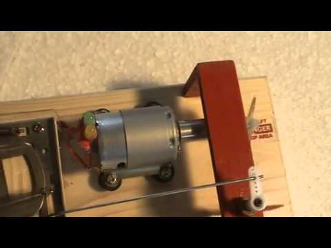
I had a Graupner telematic which was a clever device using a pulsed Geneva mechanism. I found a video of one made up for demonstration, see below.
The drawback was that the electric motor generated RF and this upset the 27Mhtz receiver.
Roy
It was frantic pressing to achieve a right turn. Often the model boat was driven with a diesel and going quite fast so it was best to rehearse first!
I had a Graupner telematic which was a clever device using a pulsed Geneva mechanism. I found a video of one made up for demonstration, see below.
The drawback was that the electric motor generated RF and this upset the 27Mhtz receiver.
Roy
▲
⟩⟩
Ray
 Vice Admiral
📝 Bob's Boards
46 Views · 1 Like
Country: 🇬🇧 United Kingdom
Online: 4 days ago
Online: 4 days ago
Bobs Boards - Tamiya used the same wiper-board principle for many years for the type of speed controller they included in all their 1/10 scale radio control cars kits.
They did work quite well in these very popular models, and the printed boards themselves were seldom the first part that failed!
Tamiya later offered their own brand electronic speed controller (ESC) as a "hop-up" part that could be bought separately to replace the standard kit supplied wiper board system.
It wasn't that long ago that Tamiya finally stopped including these wiper-board speed controllers and replaced them with an ESC in their kits as the standard part.
▲
⟩⟩
Ray
Never too old to learn
📝 Bob's Boards
51 Views · 4 Likes
Country: 🇬🇧 United Kingdom
Online: 19 seconds ago
Online: 19 seconds ago
Hi all, Bob's Boards, they were the cheap option and worked for me, there were other versions where a non-resistive pcb had low value resistors fitted, which acted as a stepped speed controller. Using the pcb idea glued to the top of a servo you could also attach micro switches that could be progessiively switched with an intermediate speed before full speed.
With the early electronic esc's they used ordinary power transistors a drop of 0.7 volt across the emitter to base junction, so you never got the full battery voltage across the motor. If the current to the motor was say 10 amps then there would be 7 Watts of power (heat) across the transistor. Hence the sometimes large heat sinks!
A partial solution to this was to put a relay with high current swiching ability in the emitter/base circuit so that when current got to maximum the relay would be activated and the contacts would short out the power transistor and deliver the full battery voltage direct to the motor.
When FET (Field Effect Transistors) took over the job there was just 0.1 volt drop so no need for the cumbersome heat sinc.
The forth-coming February edtion of Model Boats magazine should have a nostalgic look at early esc's. I am in frequent contact with the author of Flotsom and Jetsom and we discussed this, and as I had a few unopened Bob's Boards, plus some old Futaba 24 volt esc's which he wanted, I despatched them all to him as they were surplus to me.
I look forward to the article too.
regards
Roy
▲
⟩⟩
Rookysailor
Oxford-Dave
hermank
zooma
📝 Bob's Boards
64 Views · 2 Likes
Country: 🇬🇧 United Kingdom
Online: 11 hours ago
Online: 11 hours ago
That's a long way from my basic hobby approach, but it does sound interesting, even if 90% of it is way over my head.
▲
⟩⟩
Mike Stoney
Peejay
Dave in West Oxfordshire
 Lieutenant Commander
📝 Bob's Boards
71 Views · 3 Likes
Country: 🇬🇧 United Kingdom
Online: 4 days ago
Online: 4 days ago
Hi Dave
The whole setup was pretty sketchy as I needed 240V on board for the expansion box that ran the A/D - D/A conversion, the biggest issue I has was developing the software to break into the servos so my control system could utilise the servos for steering and speed. Can remember many late nights getting the millisecond pulses to work correctly.
The whole setup was pretty sketchy as I needed 240V on board for the expansion box that ran the A/D - D/A conversion, the biggest issue I has was developing the software to break into the servos so my control system could utilise the servos for steering and speed. Can remember many late nights getting the millisecond pulses to work correctly.
▲
⟩⟩
Mike Stoney
Peejay
hermank
📝 Bob's Boards
66 Views · 4 Likes
Country: 🇬🇧 United Kingdom
Online: 11 hours ago
Online: 11 hours ago
Hi Neil - all that technology over 30 years ago, with Bob's Boards as the weakest link!
I remember back to the same years when I built an Electronize ESC from the kit that used to be available and the difference between that and the Bob's Board it replaced was a revelation!
I remember back to the same years when I built an Electronize ESC from the kit that used to be available and the difference between that and the Bob's Board it replaced was a revelation!
▲
⟩⟩
roycv
Mike Stoney
Peejay
hermank
Dave in West Oxfordshire
📝 Bob's Boards
71 Views · 5 Likes
Country: 🇬🇧 United Kingdom
Online: 4 days ago
Online: 4 days ago
That brings back memories, in 1992/93 I built a 1:10 scale hull of the Royal Navy Picket Boat No.9 as a test bed for my PhD research. Built a plug, mould and had several mouldings out of the mould. Chose 1:10 as it gave me the largest hull I could fit in to the back of a Ford Sierra.
We had access to the full sized vessel as a research platform until she was dropped a crane so a scale model was the next best option for testing the AI Control System I was developing.
This had a Bob's Board fitted as well as an A-D/D-A conversion box, GPS, fluxgate compass, various 12V batteries, 12-240V inverter, log and a Tosh Laptop running my own software for data collection, Kalman filters to apply to the GPS signals and a neural network for training the control system.
I have some photos somewhere of the setup, will try and dig them out.
▲
⟩⟩
Ray
Mike Stoney
Peejay
hermank
Oxford-Dave
 Rear Admiral
📝 Bob's Boards
68 Views · 4 Likes
Country: 🇨🇭 Switzerland
Online: 1 hour ago
Online: 1 hour ago
Hey Dave,
I have something like this in my collection box! I recently had it in my hand . .
Take a photo . . .
Bb Michel-C.
I have something like this in my collection box! I recently had it in my hand . .
Take a photo . . .
Bb Michel-C.
▲
⟩⟩
Ray
AlessandroSPQR
Peejay
hermank
if you don't ask, you won't get an answer!
📝 Bob's Boards
67 Views · 9 Likes
Country: 🇬🇧 United Kingdom
Online: 11 hours ago
Online: 11 hours ago
British modellers who have been in the hobby for a while might remember (either fondly or with dread) the mechanical speed control system known as Bob's Boards'. These were a PCB with an etched resistance track, with a metal wiper moved by a servo to regulate the output.
My experience of them was that they worked, up to a point, but fine control was difficult and the tracks had a tendency to lift away from the board after a while.
Nostalgia is a funny thing, so when I was offered a look through a couple of boxes of old stock in Howes model shop this morning, I was almost tempted to buy the two Bob's Boards, unopened in their original packing. Luckily, I remembered how difficult they could be, and with a wry smile returned them to the box.
It occurs to me that some people may be more interested in the way things were and might want to give them a go - if so, ring Howes and ask for Nick (the boss there) and mention the Bob's Boards that he showed me (Dave) this morning.
▲
⟩⟩
Ray
Rookysailor
DuncanP
RogerA1
roycv
Peejay
Fred
hermank
Mike Stoney
Dave in West Oxfordshire


Login To
Remove Ads
Remove Ads