Join Us On Social Media!

|

|

|
Download The App!
Login To
Remove Ads
Remove Ads
Login To
Remove Ads
Remove Ads
Model Boats Website
Sprite
249 Posts · 11 Followers · 149 Photos · 611 Likes
Began 8 months ago by
 Vice Admiral
 United Kingdom
Follow This Thread
Not currently following
> Click to follow
> Click to follow
Latest Post 9 days ago by
( Newest Posts Shown First )
📝 Sprite
12 Views
Country: 🇬🇧 United Kingdom
Online: 15 hours ago
Online: 15 hours ago
Another vote for spirit based gloss paint 👍.
It’s what us traditional brush painters need for use on our Classic Model Power Boats.
Bob.
It’s what us traditional brush painters need for use on our Classic Model Power Boats.
Bob.
▲
⟩⟩
No likes yet
This member will receive 1 point
for every like received
This member will receive 1 point
for every like received
Never too old to learn
📝 Sprite
18 Views · 1 Like
Country: 🇬🇧 United Kingdom
Online: 1 hour ago
Online: 1 hour ago
On the subject of paint, which I probably shouldn't bring up again! I'd used water-based in our back bedroom and our son's flat and it was alright and certainly being water wash-up is a big plus. As well as being less glossy (though OK for interior household) the frustration for me is on larger areas like window boards, where the quicker drying means it is difficult to lose brush marks, it just doesn't flow well.
So when doing some work in the bathroom a couple of weeks ago I returned to oil based, what a joy! It covers better and due to it flowing better I achieved a lovely, glossy finish with barely a brush stroke in sight! 😁
Chris
So when doing some work in the bathroom a couple of weeks ago I returned to oil based, what a joy! It covers better and due to it flowing better I achieved a lovely, glossy finish with barely a brush stroke in sight! 😁
Chris
▲
⟩⟩
Ronald
Scratch building 7 Faireys at a scale of 1:12
📝 Sprite
18 Views · 2 Likes
Country: 🇬🇧 United Kingdom
Online: 1 hour ago
Online: 1 hour ago
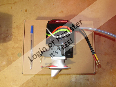
I'd finished the drawings for the Sprite outboard version awhile ago and received the outboard but hadn't done anymore with it. Partly because of other things but also I hadn't used my A3 printer since changing the computer and when I came to I couldn't get it recognised on the wireless network under Windows 11, fine under Windows 10.
Sister-in-law wanting some photos (it's a photo printer) prompted me to get it sorted, which I did, with the help of a 10m cable, as the printer is in another room. This has enabled me to print off the drawings for Sprite, blimey it is going to be big!
Good job, the motor is a big old beast! I knew it was going to be quite big, hence the bigger Sprite and something that would look right with it, but it's still impressive when you get it out of the box. It's well made and will look good mounted on a model.
TFL do a smaller one, but it's flexi-drive which I didn't really want, but more importantly it's even more of a race boat engine, so not very tall and the bottom end is curved and not very scale like. As it is, the bigger one is a "short shaft" design and the low mounting has been a bit of a design challenge as will be this part of the build I think.
I also stocked up on thicker ply for the keel etc. and other thicknesses for stock so ready to go really! But other builds still require work!
Chris
▲
⟩⟩
chugalone100
EdW
Scratch building 7 Faireys at a scale of 1:12
 Admiral
📝 Sprite
34 Views · 4 Likes
Country: 🇺🇸 United States
Online: 10 seconds ago
Online: 10 seconds ago
I agree that acrylic paints have come a long way, especially with durability. For me I still prefer to use oil based enamel paints. For years I have been using Testors, both in the small jars and small cans. The price has gone up in the past few years. The 0.25 (1/4) ounce jars run about 3 - 4 $US. That's about 12 - 16 $US an ounce. Ug!
I still find that the oil based enamels have a slightly better opaqueness over the acrylics. As for durability I usually use a clear dull or gloss oil based enamel over the acrylics.
Lately I have been using acrylics over enamels and vice versa. This is usually when I run out of one kind of paint. No problems.
Lew
▲
⟩⟩
Ronald
Madwelshman
hermank
RodC
Lew Zee (LewsModelBoats.org)
 Fleet Admiral
📝 Sprite
41 Views · 3 Likes
Country: 🇨🇦 Canada
Online: 9 hours ago
Online: 9 hours ago
Interesting read Bob and Doug, it’s not always available to have a discussion with a person in the industry be that candid about their product.
In these discussions people refer to “environmental impact or friendly products “ yet aerosol products are a pollutant too. Just look around your house and see all the different items we take for granted that in their manufacturing process are probably harmful to the environment and the ozone layer that makes up our planet.
I just as guilty of this as others. Just be careful with your choices.
▲
⟩⟩
Madwelshman
zooma
hermank
📝 Sprite
37 Views · 5 Likes
Country: 🇬🇧 United Kingdom
Online: 15 hours ago
Online: 15 hours ago
Hi Doug,
I am sorry to say that I think you have misunderstood the point that I was trying to make (and have made lots of times previously) regarding the suitability of regular water based household paints for use on any surfaces that will be exposed to water and general outdoor use.....and in this case - specifically on an r/c model boat in particular.
I have also used "car touch-up" types of acrylic aerosol spray cans with total success - but that is a very different type of paint to the water-based tins of household paint that I am referring to.
Buying a tin of gloss paint here in the UK will almost always be water-based and often described as being "easy clean".
When trying to restore or build my Classic Model Power Boats I like to try to finish them using the traditional method of hand painting them with a brush, and when I was younger, this type of paint would always be oil based and durable for use outdoors.
Water based paints were previously referred to as "emulsion paints" and were generally used for painting indoor walls and ceilings and nobody would consider them to be suitable for outdoor use where a weather-proof finish was required.
Currently the oil based paints that we always used for making "gloss paint" are now very difficult to find as they have been replaced by these latest types of "easy-clean" paints that are water based that are environmentally much more acceptable.
I have tested these environmentally preferred GLOSS paints many times over the years and have found them to be totally unsuitable for use on my Classic Model Power Boats.
One example that I have previously mentioned was when I bought an environmentally preferred tin of "easy clean" gloss paint for use on a stand that I had made for my Rapier 1.
The paint did not cover very well and took several coats to give a uniform finish, and it was not especially shiny...or gloss like.
This paint was recommended (by the manufacturers - printed on the tin!) for use outdoors on all wood and metal surfaces!
When I tested Rapier 1 for the first time I noticed that as some drips of water dropped onto the stand the paint colour changed - the drips of water were washing the colour away .
I called the technical hotline number for the paint manufacture and explained what I had witnessed and my surprise at a paint that was been sold for use outdoors (including metal surfaces) was not actually waterproof.
His reply amazed me.
He stated clearly that this type of paint was what all manufacturers were being "encouraged" to make as the traditional oil based paints (and even worse the older types that included lead) were no longer considered environmentally acceptable.
In addition, he stated that he would certainly not trust or use any of these new "easy clean" water based paints (from any manufacturer) on his front door! Instead, he would do what I am doing now, and that is to search-out the few remaining types of oil based paints that are still available.
A "tip" was offered to look for paints described as "professional" or "trade" as they usually oil based as professional painters would not use water based paints on outdoor surfaces such as doors and window frames etc.
Another tip was to look for specialist paint types such as "coach paint" that are still used to brush finish some commercial and military vehicles that need an authentic (and durable) paint type......as well as BOATS.
Coach paints (and similar types) tend to be expensive and can often be found in boat chandlers and are often used for painting canal barges and other things that need a paint applied by brush to cover wood and metal surfaces.
Finding these plants online is an alternative for those of us that do not live near a boat chandlers or marine paint specialist......and is why I am pleased to find them available online from suppliers such as eBay.
I hope this helps to clarify why I don't like to brush paint any of my r/c model boats with any of the water based environmentally friendly household "gloss" paints that most of the warehouses now stock almost exclusively here in the UK.
Bob.
▲
⟩⟩
GaryLC
Madwelshman
LewZ
hermank
Chum444
Never too old to learn
 Captain
📝 Sprite
46 Views · 2 Likes
Country: 🇬🇧 United Kingdom
Online: 1 hour ago
Online: 1 hour ago
Doug, you have been quiet for a while, are you OK
▲
⟩⟩
RNinMunich
hermank
📝 Sprite
46 Views · 4 Likes
Country: 🇩🇪 Germany
Online: 7 days ago
Online: 7 days ago
Zooma-
Re "and the current crop of water based gloss paints have proven to be totally unsuitable for use on a Classic Model Power Boat."
Sorry Bob but I can not agree.
See my Build Blog / Restoration of my Sea Scout "Jessica" from 8 years ago.
I achieved a 'glass like' finish using acrylic spray can paints from the auto branch.
Details of the paints used (including clear coat sealant) and sources are given in my Blog.
Remember: it's not just a question of the individual paint type but THE WHOLE PAINT SYSTEM must be compatible. Don't mix solvent and acrylic types and Always seal Acrylics with the system/manufacturer appropriate Clear Coat, just like the auto manufacturers do! See my blog for details.
Cheers, Doug😎
▲
⟩⟩
Madwelshman
Ronald
EdW
hermank
Young at heart 😉 Slightly older in other places.😊 Cheers Doug
📝 Sprite
43 Views · 4 Likes
Country: 🇬🇧 United Kingdom
Online: 15 hours ago
Online: 15 hours ago
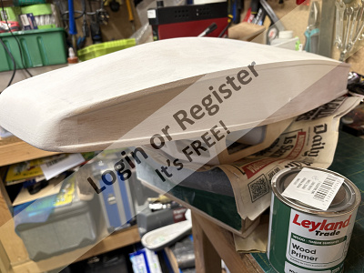
Sprite Plus.
Solvent based Primer and Gloss Paint.
I have used a little P38 filler to tidy-up and flair-in the exit of the prop shaft under the hull and given the underside of the hull its first coat of primer.
A white spirit based primer was found in Screwfix and I may have found some spirit based gloss paint on eBay that can be used for my least favourite job of brush painting the boat when the build is finished.
Finding solvent based gloss paints for brush painting is not as easy as it used be and the current crop of water based gloss paints have proven to be totally unsuitable for use on a Classic Model Power Boat.
Bob.
▲
⟩⟩
EdW
Madwelshman
hermank
chugalone100
Never too old to learn
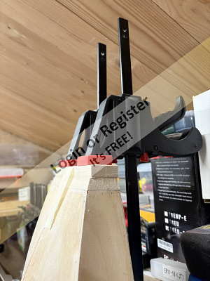
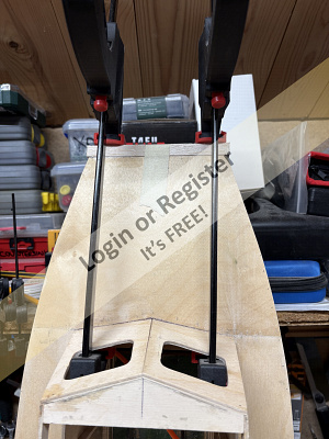
📝 Sprite
47 Views · 6 Likes
Country: 🇬🇧 United Kingdom
Online: 15 hours ago
Online: 15 hours ago
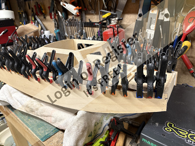
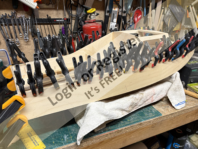
Hi Mike,
You cant have too many clamps!
...and you can pop around anytime and borrow a couple... 🤣
Bob
You cant have too many clamps!
...and you can pop around anytime and borrow a couple... 🤣
Bob
▲
⟩⟩
EdW
Madwelshman
robbob
Steve P
hermank
chugalone100
Never too old to learn


Login To
Remove Ads
Remove Ads