Join Us On Social Media!

|

|

|
Download The App!
Login To
Remove Ads
Remove Ads
Login To
Remove Ads
Remove Ads
Model Boats Website
Bidirectional motor speed reduction circuit
15 Posts · 7 Followers · 10 Photos · 14 Likes
Began 8 months ago by
 Commodore
 United States
Follow This Thread
Not currently following
> Click to follow
> Click to follow
Latest Post 8 months ago by
( Newest Posts Shown First )
📝 Bidirectional motor speed reduction circuit
26 Views · 1 Like
Country: 🇺🇸 United States
Online: 37 seconds ago
Online: 37 seconds ago
John, I am quite familiar with most of the devices needed for RC vehicles. I have a few land vehicles (trucks and a half track) that were operated by model specific RC controllers pre-installed and converted to standard RC trans/rec.
In this wide world one would think someone would have created a replacement for an inline the old resistor/rheostat for reducing bipolar voltage.
Lew
Florida ⛱️, USA
In this wide world one would think someone would have created a replacement for an inline the old resistor/rheostat for reducing bipolar voltage.
Lew
Florida ⛱️, USA
▲
⟩⟩
Scratchbuilder
Lew Zee (LewsModelBoats.org)
 Midshipman
📝 Bidirectional motor speed reduction circuit
24 Views · 2 Likes
Country: 🇬🇧 United Kingdom
Online: 12 minutes ago
Online: 12 minutes ago
hi there Lew
I have a feeling, my friend, you may have to bite the bullet with this one and alter the gearing to slow the crane down. I have been reading back through the posting and it does look like an 'all in one' circuit board that you are working with - very difficult to alter / tamper with.
I suppose though the other alternative would be - to gut the old electronics out and replace with say a Futaba receiver. Then, you would obviously have to have speed controller for the tracks on one channel (forward and back of the actual movement of the crane) - then you would require the other 3 channels for the operation of the crane itself and they could be done with small, cheap, speed controllers.
I have done this myself before on a model - but - for the winches on the crane, I used continuous rotating servos with drums attached for the cables & etc.
The speed controllers I bought came from a local Company - and I will try and find the link - because it is a long time since I made this model. I can put the link on for you if I find it.
John
▲
⟩⟩
hermank
Scratchbuilder
📝 Bidirectional motor speed reduction circuit
26 Views
Country: 🇺🇸 United States
Online: 37 seconds ago
Online: 37 seconds ago
Thanks John. I've built this circuit for a "radar" motor speed controller. Unfortunately this will not work for this application as I need the input and output reversible.
Lew
Florida ⛱️, USA
Lew
Florida ⛱️, USA
▲
⟩⟩
No likes yet
This member will receive 1 point
for every like received
This member will receive 1 point
for every like received
Lew Zee (LewsModelBoats.org)
📝 Bidirectional motor speed reduction circuit
30 Views · 1 Like
Country: 🇬🇧 United Kingdom
Online: 12 minutes ago
Online: 12 minutes ago
hi there
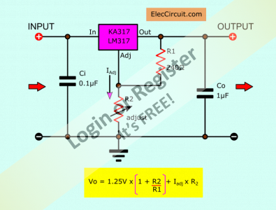
If you are handy with a soldering iron, I suppose that you could construct this little voltage regulator. This would vary the speed of your motor.
The only downside is that you only have 5 volts input which is on the low side for a lot of I.C control units.
John
If you are handy with a soldering iron, I suppose that you could construct this little voltage regulator. This would vary the speed of your motor.
The only downside is that you only have 5 volts input which is on the low side for a lot of I.C control units.
John
▲
⟩⟩
Len1
 Warrant Officer
📝 Bidirectional motor speed reduction circuit
37 Views
Country: 🇬🇧 United Kingdom
Online: 16 days ago
Online: 16 days ago
What speed are you looking for and what does the motor operate?
▲
⟩⟩
No likes yet
This member will receive 1 point
for every like received
This member will receive 1 point
for every like received
📝 Bidirectional motor speed reduction circuit
35 Views
Country: 🇺🇸 United States
Online: 37 seconds ago
Online: 37 seconds ago
I doubt that this device would work for a bunch of reasons. Thanks anyway.
Also, the output of the toy receiver is not variable. Just forward, stop, and reverse.
Lew
Florida ⛱️ ,USA
Also, the output of the toy receiver is not variable. Just forward, stop, and reverse.
Lew
Florida ⛱️ ,USA
▲
⟩⟩
No likes yet
This member will receive 1 point
for every like received
This member will receive 1 point
for every like received
Lew Zee (LewsModelBoats.org)
📝 Bidirectional motor speed reduction circuit
35 Views · 2 Likes
Country: 🇬🇧 United Kingdom
Online: 12 minutes ago
Online: 12 minutes ago
Hi ya Lew
My main concern about what you are trying to do is - the power supply from that circuit board to the crane motor may already be a variable voltage supply, by a pulse with voltage gizmo on the circuit board. Similar to the way the circuitry in a speed controller works. It sends a pulse of signals. I suppose one way of testing would be to replace the motor with a 6 volt bulb. If the bulb dims as you move your lever on your control and it starts to flash, this will be an indication that it is a pulse system. If not, you may be able to replace or fit a little gizmo from China, which I have used quite often and it is a motor speed controller from 'Ali Express'.
I will put a link on here as well, when I refind it for you.
John

▲
⟩⟩
SimpleSailor
Len1
 Lieutenant
📝 Bidirectional motor speed reduction circuit
51 Views
Country: 🇺🇸 United States
Online: 19 hours ago
Online: 19 hours ago
Doug, thanks for the info on servo speed reducers. I was not aware of them before.
Len
Len
▲
⟩⟩
No likes yet
This member will receive 1 point
for every like received
This member will receive 1 point
for every like received
LEN1
📝 Bidirectional motor speed reduction circuit
73 Views
Country: 🇺🇸 United States
Online: 37 seconds ago
Online: 37 seconds ago
Thanks Doug. I was also wondering about these servos speed reducers and if that would answer my questions. (Crane was supplied by Marquis de Peking.)
In the receiver output for channels, the red wire varies the voltage from (approximately) +5v to -5v. The black wire is common, and the white wire is sense.
So the relationship between the red and black varies in that range. The DC motor doesn't recognize that or if the polarity on the terminals is reversed for a direction change.
How about the output from the receiver I have? Is there a way of testing to see if the polarity is changing or is there a common on one wire and the other is going positive to negative?
Lew
Florida ⛱️, USA
▲
⟩⟩
No likes yet
This member will receive 1 point
for every like received
This member will receive 1 point
for every like received
Lew Zee (LewsModelBoats.org)
 Fleet Admiral
📝 Bidirectional motor speed reduction circuit
74 Views
Country: 🇩🇪 Germany
Online: 7 hours ago
Online: 7 hours ago
PS:
Lew, sorry to read of the pain scheme 🤕😭 of the crane.
Was the crane model supplied by Marquis de Sade Models?😁🤣
😎
Lew, sorry to read of the pain scheme 🤕😭 of the crane.
Was the crane model supplied by Marquis de Sade Models?😁🤣
😎
▲
⟩⟩
No likes yet
This member will receive 1 point
for every like received
This member will receive 1 point
for every like received
Young at heart 😉 Slightly older in other places.😊 Cheers Doug


Login To
Remove Ads
Remove Ads