Join Us On Social Media!

|

|

|
Download The App!
Login To
Remove Ads
Remove Ads
Login To
Remove Ads
Remove Ads
Model Boats Website
The Vosper 46” RAF Crash Tender Kit By Vintage Model Works
86 Posts · 46 Followers · 625 Photos · 826 Likes
Began 6 years ago by
 United Kingdom
Follow This Thread
Not currently following
> Click to follow
> Click to follow
Latest Post 3 years ago by
| Oldest posts shown first (Show Newest First) | (Print Booklet) |
📝 The Vosper 46” RAF Crash Tender Kit By Vintage Model Works
6 years ago by 🇬🇧 mturpin013 ( Admiral)
Admiral)✧ 48 Views · 2 Likes
Flag
💬 Add Comment
Just a small introduction, I am a retired engineer, trained as a toolmaker and practiced this in various forms for 20 plus years before going into Lecturing in engineering for 13 years then finally working on development of NVQs and VRQs for an Engineering Awarding Body. As far as My model making experience I did a little as a youngster helping my dad to build the 36 inch Crash tender and then doing some model aircraft but that was 50 years ago. I then became hooked on building a kit car which has occupied me for many years changing things and maintaining it as a recreational vehicle. This brings me up to date and instead of restoring a classic car I decided to get back to model making and this is the start of the 46 Crash Tender.
So here we go
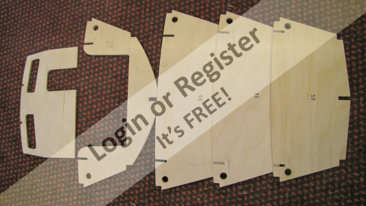
Out of the box and the contents checked off, a minor anomaly on the parts numbering but soon sorted by VMW.
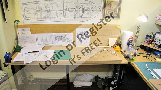
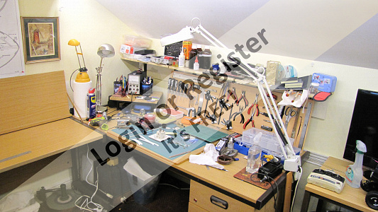
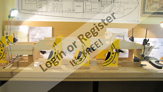
I have spent some time in kitting out a new work station in what used to be my office until I retired. I now have two workshops one upstairs and one in the basement. How good is that?
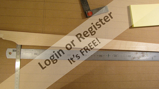
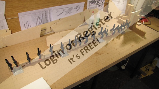
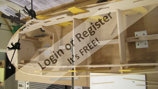
One of the of the first things was to construct a substantial building board that would give a perfectly flat base and a grid that could ensure bulkheads are square to the keel an parallel with each other also the same aspects in the vertical axis. I lined out the base board with parallel lines spaced at 25 mm and then from the centre-line at 90 degrees I marked the bulkhead positions.

So here we go
Out of the box and the contents checked off, a minor anomaly on the parts numbering but soon sorted by VMW.
I have spent some time in kitting out a new work station in what used to be my office until I retired. I now have two workshops one upstairs and one in the basement. How good is that?
One of the of the first things was to construct a substantial building board that would give a perfectly flat base and a grid that could ensure bulkheads are square to the keel an parallel with each other also the same aspects in the vertical axis. I lined out the base board with parallel lines spaced at 25 mm and then from the centre-line at 90 degrees I marked the bulkhead positions.
▲
⟩⟩
BillH
BOATSHED
Login To
Remove Ads
Remove Ads
📝 The Vosper 46” RAF Crash Tender Kit By Vintage Model Works
6 years ago by 🇬🇧 mturpin013 ( Admiral)
Admiral)✧ 54 Views · 8 Likes
Flag
💬 Add Comment
Keel base
The first puzzle was the aspect of the keel base with the first bulkhead position for B1 and the fact that they are not square and actually at 88.9 degrees This made me question as to whether the keel should lay flat on the base or the bulkhead should be in the vertical plane when fitted. This could result in a small error of the vertical B1 or a 10mm error in the keel having to be raised by 10mm at the point where the prop-shaft emerges.
A quick call Michael Cummings at VMW confirmed this should be a 90 degrees not 89 degrees. Therefore the keel lays flat as I thought it should and there would be a small gap between B1 and its vertical face. Michael Cummings said he would look into this.
▲
⟩⟩
rikster67
Harvey Kitten
molly
DaveWhittaker
BOATSHED
Dave M
SelwynWilliams
AllenA
📝 The Vosper 46” RAF Crash Tender Kit By Vintage Model Works
6 years ago by 🇬🇧 mturpin013 ( Admiral)
Admiral)✧ 54 Views · 8 Likes
Flag
💬 Add Comment
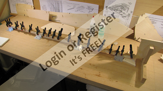
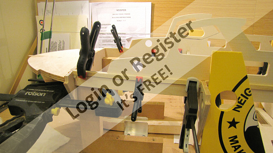
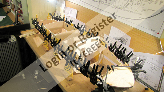
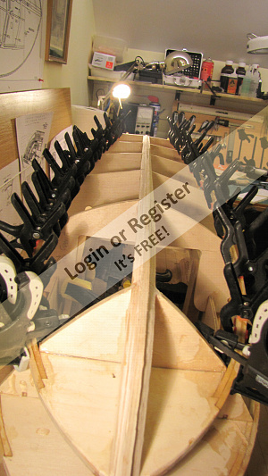
Let the build begin, first job is to cut all the keel components out and trim any pips. I found the most accurate method of marking the position of the bulkheads on the central keel was to lay the cabin sides on the keel and transfer the positions of the already cut slots in the cabin sides onto the keel. The keel was then supported with four 90 degree angle brackets, Starting with the K1 pair they are clamped in position up against B1 then drilled through with 1.8 mm drill, and a 2 mm brass pin pushed home, this was repeated inserting each bulkhead along the whole keel ensuring the bulkheads would fit after the keel components were epoxied. The brass pins are then removed, each pair are epoxied and once again the pins pushed back right through this ensures accurate positioning. As I worked along each section the assembly was clamped. Note the two angle brackets holding the keel square at bulkhead B1

▲
⟩⟩
DaveWhittaker
BOATSHED
Harvey Kitten
Dave M
SelwynWilliams
robbob
marky
sjkraft
📝 Bulkhead
6 years ago by 🇬🇧 mturpin013 ( Admiral)
Admiral)✧ 54 Views · 9 Likes
Flag
💬 Add Comment
Bulkhead
Time to fit the B1 bulkhead, at this point I was advised (by a well-known crash tender builder, more about him later) that I should dry fit the entire front end and to chamfer the appropriate parts prior to final assembly leaving only final trimming when fitting the skins (a good call). Again keeping all components square, vertical and level by using height gauges squares etc. they are pre-drilled and temporally pinned to ensure that they fit correctly. its then all taken apart before final assembly with epoxy and pushing the brass pins fully home and clamped where required.


Time to fit the B1 bulkhead, at this point I was advised (by a well-known crash tender builder, more about him later) that I should dry fit the entire front end and to chamfer the appropriate parts prior to final assembly leaving only final trimming when fitting the skins (a good call). Again keeping all components square, vertical and level by using height gauges squares etc. they are pre-drilled and temporally pinned to ensure that they fit correctly. its then all taken apart before final assembly with epoxy and pushing the brass pins fully home and clamped where required.
▲
⟩⟩
DaveWhittaker
BOATSHED
Dave M
SelwynWilliams
sjkraft
AllenA
Colin H
RNinMunich
robbob
📝 More Bulkheads
6 years ago by 🇬🇧 mturpin013 ( Admiral)
Admiral)✧ 54 Views · 8 Likes · 3 Comments
Flag
💬 Add Comment
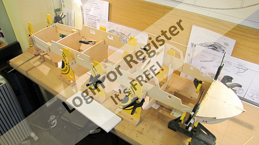
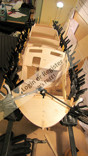
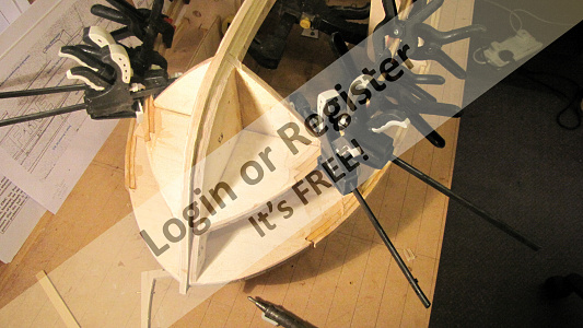
All the bulkhead parts are made ready for assembly. I decided at this point modify CF2 and B2. B2 to enable easy access for further detailing of the cabin at a later stage and CF2 I cut out what will be the door opening into the cockpit. Each of the bulkheads had 2 x 12 mm holes drilled just below deck level for future wiring runs; they also needed support to secure them at 90 degrees so I made a number of right angle squares to support them squarely and at equal height at each side, these were secured with a temporary brass pin. The spacing at the keel was pre-determined when building the keel components, however the tops need correct spacing by dry fitting the cabin sides and just checking that each side measures the same height, finally the back end of the keel needs supporting to keep everything square. Each of the cabin sides and bulkheads can now be dismantled and reassembled with epoxy resin. NOTE at this stage only the bulkheads are epoxied to the keel, the cabin sides and CF2 are only there to ensure the bulkheads are square and correctly spaced at this stage.


▲
⟩⟩
DaveWhittaker
BOATSHED
Dave M
Harvey Kitten
Nutbourne
SelwynWilliams
robbob
RNinMunich
|
💬 More Bulkheads
6 years ago by 🇬🇧 robbob (
Admiral)✧ 49 Views · 2 Likes
Flag
Ah...I see what you are trying to achieve now, I've never seen that done but that's not to say it isn't possible so if you think you can engineer it...why not 😜👍.
Rob. ▲
⟩⟩
BOATSHED
Dave M
|
|
Login To
Remove Ads 💬 More Bulkheads
6 years ago by 🇬🇧 mturpin013 (
Admiral)✧ 50 Views · 3 Likes
Flag
Robbob hopefully the cabin roof will be detachable/hinged and the bulkhead at the back of the cabin will be solid apart from the door, so the bulkhead needs extending down to the floor when fitted, this why the cutout is in B2, its at floor level
That's the though at the moment. ▲
⟩⟩
BOATSHED
Dave M
RNinMunich
|
|
💬 More Bulkheads
6 years ago by 🇬🇧 robbob (
Admiral)✧ 50 Views · 3 Likes
Flag
Hi Michael.
You might want to consider enlarging the cut out in CF2 to allow you to get your hand easily into the interior of the cockpit. I think the small 'door' cut out will restrict access if you intend to detail this area with a wheel, throttles and instruments etc. And getting your hand inside is really helpful when it comes to glazing the windows. Apart from that it looks like a 'proper job' 👍 Robbob. ▲
⟩⟩
BOATSHED
Dave M
RNinMunich
|
📝 Cabin sides and deck supports
6 years ago by 🇬🇧 mturpin013 ( Admiral)
Admiral)✧ 60 Views · 12 Likes · 2 Comments
Flag
💬 Add Comment
Before we continue I must mention some fine detail that should have been mentioned in the previous build update and that is the preparation of the cabin sides. Because the bow end of the cabin sides narrow there is a need to score/cut through partially in the places indicated in the build instructions, this is around the cabin side window and enables the side to bend without cracking the external faces, and this also applies to the rear of the cabin sides where it joins B5. The cabin side extensions can also be glued into position as well
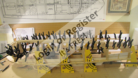
To continue, having secured all the bulkheads to the keel I can now epoxy the cabin sides to the bulkheads ensuring that the height is maintained side to side and bends smoothly round to the bow and stern. Allowing this to set for a couple of hours I can fit the deck stringers from ¼ x ⅛. These are cut to length to suite the gaps between the bulkheads and glued in place using aliphatic resin glue. I also added some extra support where the cabin side extensions are since its only a butt joint.


To continue, having secured all the bulkheads to the keel I can now epoxy the cabin sides to the bulkheads ensuring that the height is maintained side to side and bends smoothly round to the bow and stern. Allowing this to set for a couple of hours I can fit the deck stringers from ¼ x ⅛. These are cut to length to suite the gaps between the bulkheads and glued in place using aliphatic resin glue. I also added some extra support where the cabin side extensions are since its only a butt joint.
▲
⟩⟩
Harvey Kitten
DaveWhittaker
Donnieboy
SelwynWilliams
BOATSHED
marky
Krampus
Dave M
sjkraft
neilmc
RNinMunich
robbob
|
💬 Cabin sides and deck supports
6 years ago by 🇬🇧 jarvo (
 Lieutenant) Lieutenant)✧ 53 Views · 3 Likes
Flag
Just a thought mate, when you have completed the bulkheads etc, before fitting the skins, seal the wood with something like Zpoxy, this will make it easier when sealing the rest of the hull.
Mark ▲
⟩⟩
BOATSHED
Dave M
RNinMunich
|
|
💬 Cabin sides and deck supports
6 years ago by 🇬🇧 Dave M (
 Vice Admiral) Vice Admiral)✧ 52 Views · 2 Likes
Flag
Good building practice. Nice solid baseboard and lots of vertical jigs and clamps holding everything square whilst the glue dries.
I look forward to following your build ▲
⟩⟩
BOATSHED
Gascoigne
|
📝 1st Gunwhale stringers
6 years ago by 🇬🇧 mturpin013 ( Admiral)
Admiral)✧ 62 Views · 8 Likes · 2 Comments
Flag
💬 Add Comment
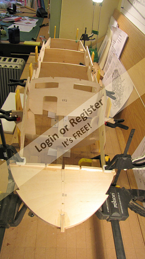
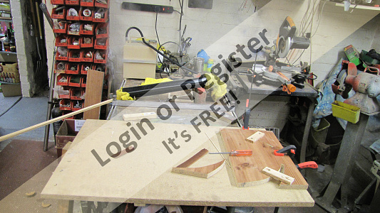
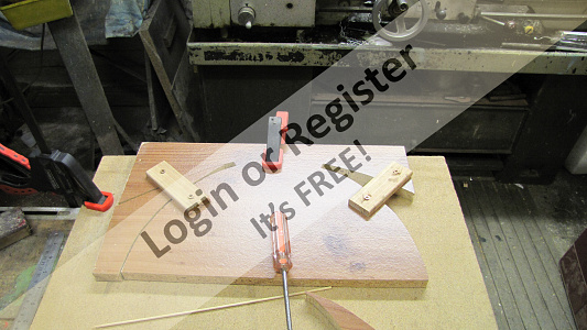
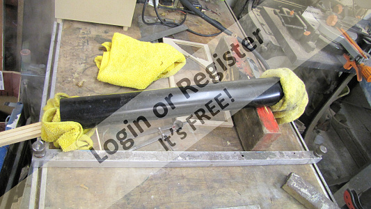
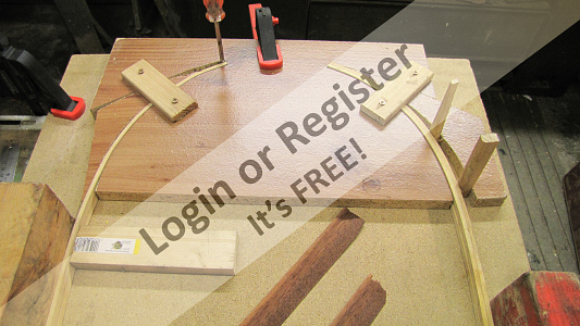
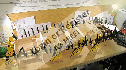
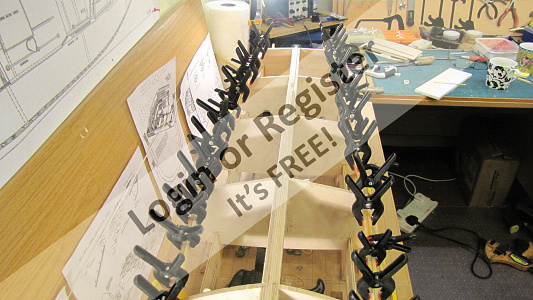
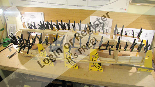
First job is to trim all the bulkhead corners so the stringers sit flat against each bulkhead. We can then start to trial fit each side to see what sort of curvature will be needed to steam the stringers prior to final fitting. I decide to make a jig for the stringers to “set” after steaming, I made this jig to accommodate all 4 stringers creating the same curvature, as the minor differences in curve will be flattened out during the clamping process. I used a domestic wallpaper steamer/striper and a piece of 4” plastic drain pipe blocked at both ends with a piece of cloth and steamed for about 20 minutes. The 4 stringers were then placed in the jig and locked into place with wedges and clamps. These were then left for a couple of days to thoroughly dry out
After steaming and setting, the stringers were dry pinned to the breast hook on both sides with brass pins, then followed back to the stern drilling and pinning to each stringer to the bulkheads as I went back. Being satisfied with the fit I now removed all the pins and started again from the front and epoxied and pinned each bulkhead on both sides.

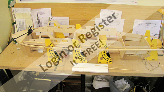


After steaming and setting, the stringers were dry pinned to the breast hook on both sides with brass pins, then followed back to the stern drilling and pinning to each stringer to the bulkheads as I went back. Being satisfied with the fit I now removed all the pins and started again from the front and epoxied and pinned each bulkhead on both sides.
▲
⟩⟩
Clive
DaveWhittaker
BigAlio
BOATSHED
Harvey Kitten
RNinMunich
Dave M
robbob
|
💬 1st Gunwhale stringers
6 years ago by 🇨🇦 Ronald (
Admiral)✧ 55 Views · 0 Likes
Flag
This boat looks like it will be very heavy using those plywood bulkheads.
▲
⟩⟩
No likes yet
This member will receive 1 point for every like received |
|
💬 1st Gunwhale stringers
6 years ago by 🇬🇧 robbob (
Admiral)✧ 57 Views · 2 Likes
Flag
Hi Michael.
Good idea with the jigs, it certainly minimises the possibility of snapping the stringers while they 'set'. Rob. ▲
⟩⟩
Dave M
BOATSHED
|
📝 2nd Gunwhale stringers
6 years ago by 🇬🇧 mturpin013 ( Admiral)
Admiral)✧ 60 Views · 8 Likes · 3 Comments
Flag
💬 Add Comment
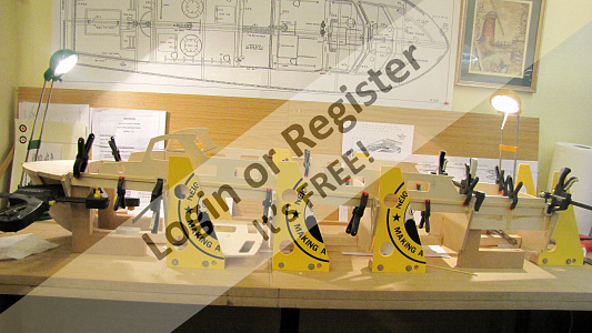
Now for the more difficult stringer, this one has already been steamed and set in the jig. The outer stringer has to be put on using glue only and clamps, so no nails at all since it has to shaped to the profile of the bulkheads over its entire length hopefully using a jack plane (which don’t like nails). Clamps at the ready and glue in hand and away we go,
▲
⟩⟩
Northernflotsam
DaveWhittaker
BigAlio
BOATSHED
RNinMunich
robbob
Dave M
Colin H
|
💬 2nd Gunwhale stringers
6 years ago by 🇬🇧 mturpin013 (
Admiral)✧ 57 Views · 2 Likes
Flag
Thanks Dave you beat me to it
▲
⟩⟩
BOATSHED
SelwynWilliams
|
|
Login To
Remove Ads 💬 2nd Gunwhale stringers
6 years ago by 🇬🇧 Dave M (
Vice Admiral)✧ 57 Views · 2 Likes
Flag
Ron
It'a a 46" model so the wood is the correct size. You have asked about clamps in your post and there are plenty of examples in this blog, you should subscribe to follow progress. The kits by Vintage Models have been around fore a few years and make into a nice model if built carefully as in this model. ▲
⟩⟩
BOATSHED
SelwynWilliams
|
|
💬 2nd Gunwhale stringers
6 years ago by 🇨🇦 Ronald (
Admiral)✧ 56 Views · 1 Like
Flag
Is this a kit, using kit wood? The parts look like they will add too much weight. Am I correct?
▲
⟩⟩
BOATSHED
|
📝 Chine stringers
6 years ago by 🇬🇧 mturpin013 ( Admiral)
Admiral)✧ 61 Views · 7 Likes · 2 Comments
Flag
💬 Add Comment
Chine stringers
Again first job is to trim all the bulkhead corners so the stringers sit flat against each bulkhead. We can then start to trial fit each side to see what sort of curvature we need. This time I needed a tighter curve (2.5 litre paint tin) so again using a scrap piece chip board I made another jig. The stringers are fitted in the same sequence as the gunwhale stringers that is the first pair are trial pinned, then epoxied and fully pinned. When fully set the second pair can be fitted but this time using clamps only, no pins, to allow for trimming at a later stage. Then allow some time for it to set and check that all this tension in both sets of stringers hasn't caused any twisting or misalignment.

Again first job is to trim all the bulkhead corners so the stringers sit flat against each bulkhead. We can then start to trial fit each side to see what sort of curvature we need. This time I needed a tighter curve (2.5 litre paint tin) so again using a scrap piece chip board I made another jig. The stringers are fitted in the same sequence as the gunwhale stringers that is the first pair are trial pinned, then epoxied and fully pinned. When fully set the second pair can be fitted but this time using clamps only, no pins, to allow for trimming at a later stage. Then allow some time for it to set and check that all this tension in both sets of stringers hasn't caused any twisting or misalignment.
▲
⟩⟩
DaveWhittaker
BigAlio
BOATSHED
RNinMunich
Donnieboy
SelwynWilliams
Dave M
|
💬 Chine stringers
6 years ago by 🇬🇧 mturpin013 (
Admiral)✧ 58 Views · 3 Likes
Flag
Its all material I had lying around in my workshop, I never throw anything away so you can imagine the amount of "stuff" I have in my basement. The Yellow angle brackets are made of old neighbourhood watch signs they are made of 1/4" plasticard
▲
⟩⟩
BOATSHED
SelwynWilliams
Donnieboy
|
|
💬 Chine stringers
6 years ago by 🇩🇪 RNinMunich (
 Fleet Admiral) Fleet Admiral)✧ 56 Views · 1 Like
Flag
Great work, LOVE the jigs 👍👍
When I built my destroyer (many many moons ago🤔) I just used loads of panel pins hammered into a chunk of pine board. You way is much more elegant. 😉 ▲
⟩⟩
BOATSHED
|
📝 Rudder, water pickup and skeg
6 years ago by 🇬🇧 mturpin013 ( Admiral)
Admiral)✧ 62 Views · 9 Likes · 1 Comment
Flag
💬 Add Comment
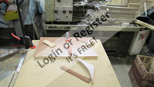
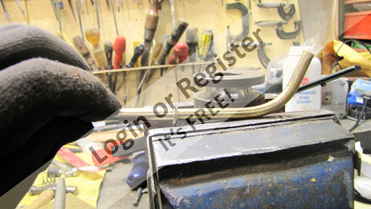
At this point I decided to fit the rudder tube, water pick up and skeg. I was able to mount the boat in the machine vice by gripping the keel; this ensured that the holes are drilled absolutely true and square, 2 x 8mm holes are needed to take both the rudder tube and water scoop. I purchased the rudder assembly from a well-known supplier but I didn’t like any of the proprietary water scoop tubes on offer so decided to make my own. Whilst the boat is in the vice I also decided to machine the slot for the skeg to fit in. This required drilling a series of 2mm holes and then opening them up into a slot using a long series slot drill again giving an accurate slot which the skeg can locate into.
Water scoop
Having dealt with the woodwork, I turned my attention to metalwork. To bend the ¼” brass tube successfully it has to be annealed, (cherry red and quenched in water), then inserting a tight fitting spring inside the tube to stop any kinking I gently pressed it round a former to the correct shape. Springs removed I filed the end to the correct angle which gives an oval opening, but the end didn’t look finished, so I machined a thin spacer and then squashed it to suit the oval end and silver soldered it to the end of the tube, this gives a much better visual appearance.
▲
⟩⟩
Mataroa
DaveWhittaker
BigAlio
BOATSHED
robbob
RNinMunich
Donnieboy
Colin H
Dave M
|
💬 Rudder, water pickup and skeg
6 years ago by 🇩🇪 RNinMunich (
Fleet Admiral)✧ 56 Views · 1 Like
Flag
An excellent tutorial, splendid stuff 👍👍👍
Several years ago I forgot the annealing stage, while making davits for my destroyer, and jammed the spring into the tube 😡 The tube didn't kink but it looked like an earthworm 🤔 ▲
⟩⟩
BOATSHED
|


Login To
Remove Ads
Remove Ads