Join Us On Social Media!

|

|

|
Download The App!
Login To
Remove Ads
Remove Ads
Login To
Remove Ads
Remove Ads
Model Boats Website
36" Thames River Police Launch by Robbob
46 Posts · 18 Followers · 403 Photos · 574 Likes
Began 6 years ago by
 United Kingdom
Follow This Thread
Not currently following
> Click to follow
> Click to follow
Latest Post 5 years ago by
| Oldest posts shown first (Show Newest First) | (Print Booklet) |
📝 36" Thames River Police Launch by Robbob
6 years ago by 🇬🇧 robbob ( Admiral)
Admiral)✧ 57 Views · 6 Likes
Flag
💬 Add Comment
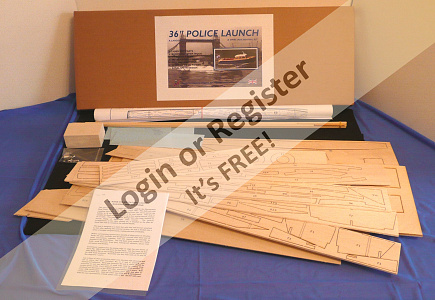
After the successful build of the ‘Vintage Model Works’ RAF Crash Rescue Tender I was asked by Mike Cummings of VMW if I would undertake to build a prototype of their new model with the aim of checking the construction method and the assembly instructions for accuracy before the kit is put into production.
The model is a ‘Thames River Police Launch’ and is based on the original design by Phil Smith for the Veron company, this was a very popular model kit in the late 50’s and 60’s and sold for the princely sum of 43 shillings and tuppence, approximately £2.15 in today’s money but an equivalent cost of £48.50 in 1960.
This design has been updated to accommodate electric propulsion and radio control by Colin Smith, the son of the original designer and it has been re-scaled to be 36” in length where the original was 24” which gives much more scope for detailing and provides more ‘hiding room’ for the drive, control systems and all the associated wiring.
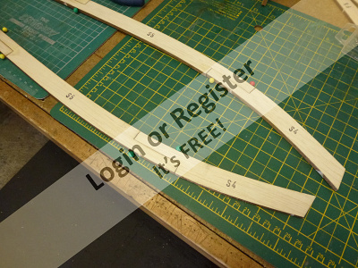
The kit produced by VMW uses the same construction techniques as the original and the materials are a combination of balsa and plywood both of which a laser and CNC cut for precision.
The ply and balsa materials supplied are of very high quality as one would expect from VMW and all the stripwood for the chines, rubbing strakes and deck detailing is included, even the dowel required for the mast is in the box, very comprehensive!
The kit also includes white metal fittings such as the fairleads and stanchions, and the searchlight and horns. The glazing for the windows comes in the kit too.
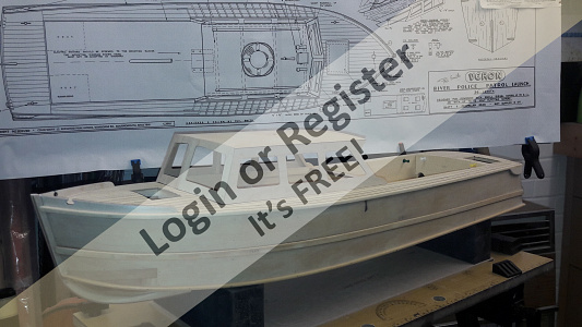
The instruction sheet supplied is in need of revision as it is largely taken directly from the original as written by Phil Smith and some of the terminology needs updating, for instance the ply bottom and side skins are referred to as ‘strakes’ but I understand that a re-write of the instructions is in hand along with an updated plan showing the best positioning for the motor, prop-shaft, battery, ESC, receiver, rudder and servo.
During construction I have added a few additional pieces of ply or balsa as reinforcement or supports and substituted some balsa parts for ply where I thought a stronger material would be better. I also added some hatches to give access to the wiring at the bow and the rudder & servo at the stern but largely I have not gone ‘off plan’ to any extent.
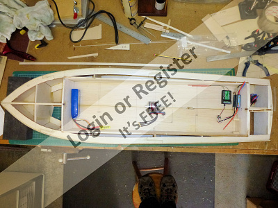
The pictures show the model in it’s present state (Nov 2018) and is ready for painting and finishing.

The model is a ‘Thames River Police Launch’ and is based on the original design by Phil Smith for the Veron company, this was a very popular model kit in the late 50’s and 60’s and sold for the princely sum of 43 shillings and tuppence, approximately £2.15 in today’s money but an equivalent cost of £48.50 in 1960.
This design has been updated to accommodate electric propulsion and radio control by Colin Smith, the son of the original designer and it has been re-scaled to be 36” in length where the original was 24” which gives much more scope for detailing and provides more ‘hiding room’ for the drive, control systems and all the associated wiring.
The kit produced by VMW uses the same construction techniques as the original and the materials are a combination of balsa and plywood both of which a laser and CNC cut for precision.
The ply and balsa materials supplied are of very high quality as one would expect from VMW and all the stripwood for the chines, rubbing strakes and deck detailing is included, even the dowel required for the mast is in the box, very comprehensive!
The kit also includes white metal fittings such as the fairleads and stanchions, and the searchlight and horns. The glazing for the windows comes in the kit too.
The instruction sheet supplied is in need of revision as it is largely taken directly from the original as written by Phil Smith and some of the terminology needs updating, for instance the ply bottom and side skins are referred to as ‘strakes’ but I understand that a re-write of the instructions is in hand along with an updated plan showing the best positioning for the motor, prop-shaft, battery, ESC, receiver, rudder and servo.
During construction I have added a few additional pieces of ply or balsa as reinforcement or supports and substituted some balsa parts for ply where I thought a stronger material would be better. I also added some hatches to give access to the wiring at the bow and the rudder & servo at the stern but largely I have not gone ‘off plan’ to any extent.
The pictures show the model in it’s present state (Nov 2018) and is ready for painting and finishing.
▲
⟩⟩
Madwelshman
hmsnostalgia
Martin555
BOATSHED
Geoffrhoose
fact77
Login To
Remove Ads
Remove Ads
📝 Constructing 'The Box'
6 years ago by 🇬🇧 robbob ( Admiral)
Admiral)✧ 64 Views · 15 Likes · 3 Comments
Flag
💬 Add Comment
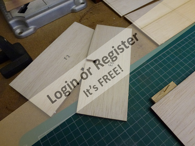
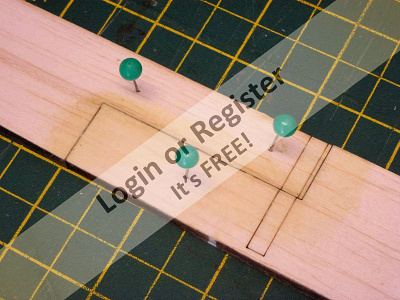
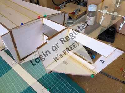
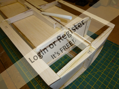
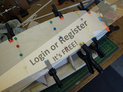
Phil Smith, the original designer of the Thames River Police Launch, based the construction on a rigid box structure around which bulkhead formers are fixed to give the hull it’s shape, a design feature of many of the Veron kits.
In the Vintage Model Works kit all the components of this box are laser cut and require no additional trimming before assembly, I have used Titebond 2 aliphatic glue throughout the construction as it bonds wood very firmly and dries quickly too.
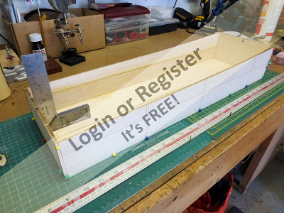
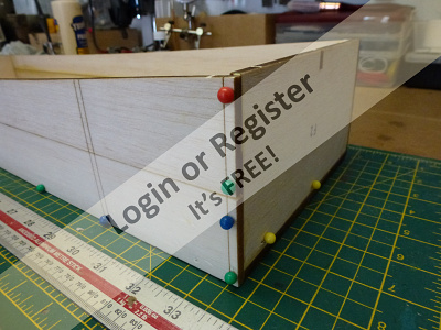
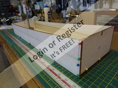
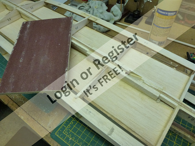
I started by joining the edges of the two sheets of balsa that form the base of the box, these were held firmly together with some scrap wood and weighted down on the cutting mat and left to dry.
Meanwhile the box sides were similarly glued together taking care that the two pieces that form each box side are in perfect alignment using the laser etched vertical lines that mark the bulkhead former positions, these were also wedged together and weighted while the glue set.
Once the bottom and sides are dry the ends can be added to complete the box construction, a try-square was used to check the box for accuracy and everything was held together with some ‘push pins’ while the glue set.
As this box forms the foundation of the hull it’s essential that there’s no twist or anything out of square.
This was all done in one evening, clearly the assembly of this kit could be completed quite rapidly if you really wanted too!

In the Vintage Model Works kit all the components of this box are laser cut and require no additional trimming before assembly, I have used Titebond 2 aliphatic glue throughout the construction as it bonds wood very firmly and dries quickly too.
I started by joining the edges of the two sheets of balsa that form the base of the box, these were held firmly together with some scrap wood and weighted down on the cutting mat and left to dry.
Meanwhile the box sides were similarly glued together taking care that the two pieces that form each box side are in perfect alignment using the laser etched vertical lines that mark the bulkhead former positions, these were also wedged together and weighted while the glue set.
Once the bottom and sides are dry the ends can be added to complete the box construction, a try-square was used to check the box for accuracy and everything was held together with some ‘push pins’ while the glue set.
As this box forms the foundation of the hull it’s essential that there’s no twist or anything out of square.
This was all done in one evening, clearly the assembly of this kit could be completed quite rapidly if you really wanted too!
▲
⟩⟩
Madwelshman
hmsnostalgia
drspock
Martin555
Geoffrhoose
BOATSHED
DaveWhittaker
Joe727
Sakibian
Missouri
muddy
mturpin013
rolfman2000
RNinMunich
Donnieboy
|
💬 Re: Constructing 'The Box'
5 years ago by 🇬🇧 Skydive130 (
 Rear Admiral) Rear Admiral)✧ 53 Views · 2 Likes
Flag
I have just taken delivery of this kit, and the joy opening the box and getting that wafting smell of fresh wood, nothing like it!
Having check the excellent quality laser cut wood against the parts list, it seems that the basic box built first is now supplied as 6mm and 5mm ply instead of balsa. Can I presume this is a change to the test kit? I am not worried about the extra weight, less ballast at the end. My only other issue now is trying to source the HobbyKing SK3 840kv motor you have used in your beautiful model as it’s currently out of stock in the Uk and EU, living only 3 miles from HobbyKing UK means I can order and sometimes pick up same day. Does anyone else have an suitable alternative recommendations for the motor if I cannot source an SK3. I could order from HobbyKing in HK as showing in stock, but the postage is high? ▲
⟩⟩
Madwelshman
Martin555
|
|
Login To
Remove Ads 💬 Constructing 'The Box'
6 years ago by 🇬🇧 rolfman2000 (
 Warrant Officer) Warrant Officer)✧ 54 Views · 2 Likes
Flag
Looking forward to more Robbob. Cheers, Dave W 😊
▲
⟩⟩
BOATSHED
doghouse
|
|
💬 Constructing 'The Box'
6 years ago by 🇬🇧 mturpin013 (
Admiral)✧ 53 Views · 1 Like
Flag
Keep it coming! its looking good
▲
⟩⟩
BOATSHED
|
📝 Assembling the keel & adding bulkhead formers.
5 years ago by 🇬🇧 robbob ( Admiral)
Admiral)✧ 63 Views · 14 Likes · 4 Comments
Flag
💬 Add Comment
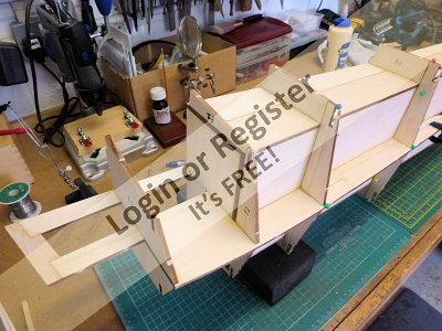
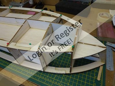
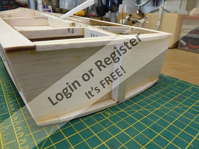
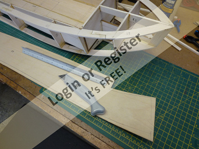
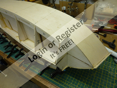
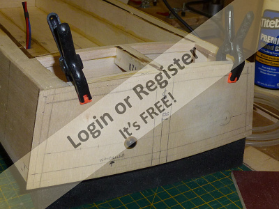
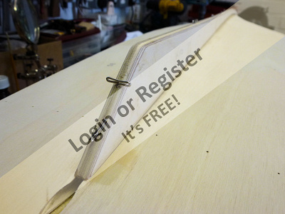
With the box assembled and the glue fully cured the next stage is to glue the inner keel parts together and fix it to the underside of the box.
The keel consists of four pieces that need to be jointed whilst on a flat surface, the instructions suggest that the parts are best assembled whilst laid over the plan with a transparent protective sheet between to ensure accurate alignment.
A gap is left in the keel for the prop shaft and this gap is laminated over by some additional keel pieces on either side.
I chose to deviate from the instructions here and fit these pieces after the prop shaft was in place to ensure a snug fit, I have it on order from Model Boat Bits along with the prop and rudder.
The assembled keel is glued in place along the centre line of the inverted box and when dry the bulkhead formers can be added.
The positions of all the formers are clearly marked on the box and the underside formers are added first followed by the side formers and lastly the bow formers, and the assembly set aside to dry.
I’d almost forgotten how easy it is to work with balsa, it takes glue and pins readily and assembling this model is a joy, however, shaping the solid balsa bow blocks to the correct profiles will be an interesting challenge.
But I don’t need to do that for a while yet.
▲
⟩⟩
stefan7964
Madwelshman
hmsnostalgia
drspock
Martin555
Geoffrhoose
BOATSHED
DaveWhittaker
TOWN3810
Sakibian
Missouri
muddy
rolfman2000
RNinMunich
|
💬 Assembling the keel & adding bulkhead formers.
5 years ago by 🇬🇧 mturpin013 (
Admiral)✧ 53 Views · 2 Likes
Flag
Now Plank on frame really sets my imagination going, I have to say that i am a builder rather than a sailor and get immense pleasure from problem solving and just creating structures.
I will be looking for a suitable subject after the Crash Tender which at the moment is taking some time with fiddly bits that don't seem to advance the the overall vision of the project so apologies for the lack of "blog" Any suggestions? ▲
⟩⟩
Madwelshman
BOATSHED
|
|
Login To
Remove Ads 💬 Assembling the keel & adding bulkhead formers.
5 years ago by 🇬🇧 robbob (
Admiral)✧ 54 Views · 3 Likes
Flag
Hi Mike.
The majority of Phil Smith's Veron designs were around this principle, just as the Aerokits/KeilKraft designs were based on the 'egg crate' method. Both methods are very successful and popular over the years as many modellers will attest, and the hull can be completed really quite quickly. 'Plank on frame' is probably as common if not more and a great deal more time consuming but far better able to reproduce complex hull shapes. Never tried the latter..perhaps one day. ▲
⟩⟩
Madwelshman
hmsnostalgia
BOATSHED
|
|
💬 Assembling the keel & adding bulkhead formers.
5 years ago by 🇬🇧 mturpin013 (
Admiral)✧ 53 Views · 2 Likes
Flag
Looking good although I had not seen the method of building round a box before, it takes some time before the shape of the craft can be seen.
▲
⟩⟩
stefan7964
BOATSHED
|
|
💬 Assembling the keel & adding bulkhead formers.
5 years ago by 🇬🇧 rolfman2000 (
Warrant Officer)✧ 53 Views · 1 Like
Flag
Coming along nicely Robbob. As the saying goes "Don't talk to me about balsa bow blocks" 😆 And yes, you don't have to do those yet lol. I may just follow you with one of these to run alongside my original Veron one from 1966/7. Hope they have them for sale soon . Best wishes, Dave W 😊
▲
⟩⟩
BOATSHED
|
📝 Upper & Lower Chines
5 years ago by 🇬🇧 robbob ( Admiral)
Admiral)✧ 61 Views · 12 Likes · 7 Comments
Flag
💬 Add Comment
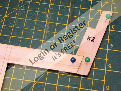
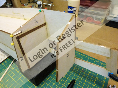
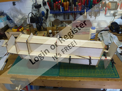
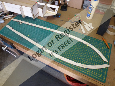
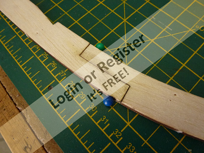
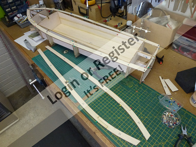
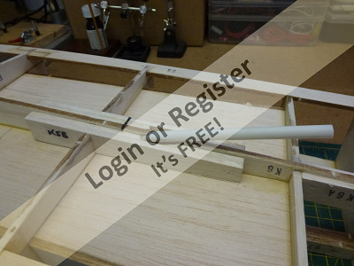
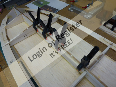
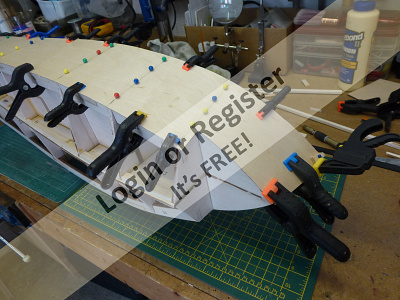
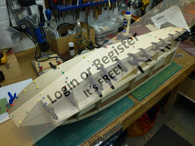
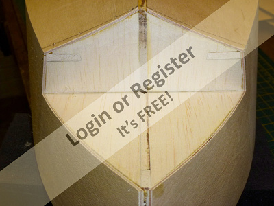
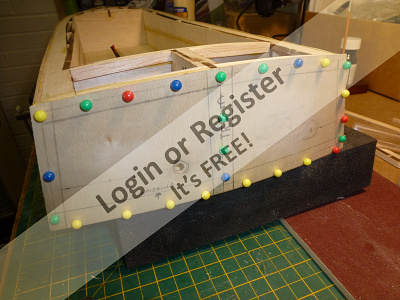
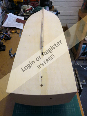
The next stage is to assemble and fit the upper and lower chines to the bulkhead formers.
Each chine is made from three parts that are step jointed together, the instructions recommend using the plan to ensure correct alignment with a protective transparent paper between, however the cutting accuracy of the parts is such that having checked the alignment over the plan I was confident that assembling and glueing them together on the cutting mat would be OK. The upper chines were assembled first and when set were glued and pinned to the tops of the bulkhead formers with the fronts butting against the K1 keel former at the prow.
The lower chines were assembled in the same fashion and when dry are glued and set into the slots in the bulkhead formers.
Finally the stern former F7 is added and the whole assembly set aside to dry.
The hull is quickly taking shape now and even at this stage is very rigid and yet remarkably light.
▲
⟩⟩
stefan7964
Madwelshman
hmsnostalgia
Martin555
Geoffrhoose
BOATSHED
DaveWhittaker
octman
Sakibian
Missouri
mturpin013
RNinMunich
|
💬 Upper & Lower Chines
5 years ago by 🇬🇧 mturpin013 (
Admiral)✧ 53 Views · 1 Like
Flag
Hi Robbob, thanks for the heads up on London Model Engineering Exhibition at 'Ally Pally' in January 2019. I am hoping to be there, Just to see your masterpiece !
▲
⟩⟩
BOATSHED
|
|
Login To
Remove Ads 💬 Upper & Lower Chines
5 years ago by 🇬🇧 robbob (
Admiral)✧ 55 Views · 4 Likes
Flag
Hi Doug.
All credit due to Phil Smith and his original design for that actually... Hi rolfman2000 I hope SWMBO is good to her word as I happen to know that the kit is now available to buy from Vintage Model Works 😊👍 I'm told the price is £185.00 + P&P and there's also an optional stand/carrying box which is CNC cut to the hull profile for an additional £10.00 That sounds a bit of a bargain too. Contact Mike Cummings at VMW for more information: ▲
⟩⟩
Madwelshman
hmsnostalgia
BOATSHED
RNinMunich
|

|
💬 Upper & Lower Chines
5 years ago by 🇬🇧 rolfman2000 (
Warrant Officer)✧ 54 Views · 2 Likes
Flag
Oh how this brings memories flooding back from 50 years ago, seeing the same construction as my original Veron Police launch (that's sat in the garage), going together. I bet the fit is a darned sight better than it was all those years ago, what with cad laser cut pieces and cad designs as well. I'm following this with even more interest, as I have permission of SWMBO to get the new bigger kit when it becomes available. Fingers crossed, not long now. Keep the installments coming Robbob. Best wishes, Dave W 😊
▲
⟩⟩
BOATSHED
RNinMunich
|
|
💬 Upper & Lower Chines
5 years ago by 🇩🇪 RNinMunich (
 Fleet Admiral) Fleet Admiral)✧ 54 Views · 2 Likes
Flag
Simple Rob,
Instead of attempting some almost impossible bends of thin (0.5mmx5mm )planks, I'll cut it out of 3 interlocking pieces (each side) of 1.5mm mahog sheet. Will probably end up looking more like it would have been done on an original 😊 Cheers, Doug 😎 ▲
⟩⟩
BOATSHED
Donnieboy
|
|
💬 Re: Upper & Lower Chines
5 years ago by 🇬🇧 robbob (
Admiral)✧ 54 Views · 2 Likes
Flag
Hi Doug.
Not sure how I've helped you out with your caprail but thanks for the compliment 👍. Mike. The boat gets a lot heavier once the ply skins and planking goes on, I hope it doesn't need balasting as there's not too many places to hide it away 🤔. ▲
⟩⟩
hmsnostalgia
BOATSHED
|
|
💬 Upper & Lower Chines
5 years ago by 🇬🇧 mturpin013 (
Admiral)✧ 54 Views · 2 Likes
Flag
Thats coming on nicely and as you say it looks quite a rigid construction. How much of a bonus is a lightweight construction V an all ply construction as I assume you may have to put some ballast in the finished model. not thtat I have any experience on the subject
▲
⟩⟩
BOATSHED
Geoffrhoose
|
|
💬 Upper & Lower Chines
5 years ago by 🇩🇪 RNinMunich (
Fleet Admiral)✧ 53 Views · 1 Like
Flag
Excellent Rob👍
Thanks for showing me how to make the mahogany caprail for my cutter 😊 "More power to your chines"😁 Cheers Doug 😎 ▲
⟩⟩
BOATSHED
|
📝 Stern & keel formers
5 years ago by 🇬🇧 robbob ( Admiral)
Admiral)✧ 64 Views · 15 Likes · 3 Comments
Flag
💬 Add Comment
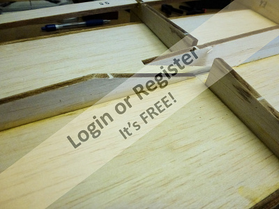
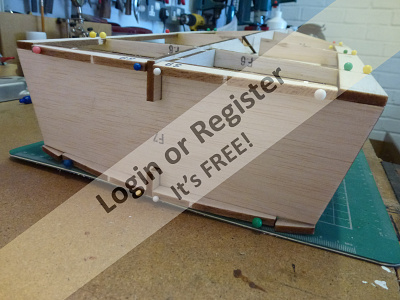
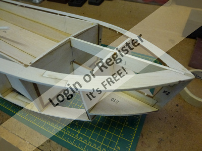
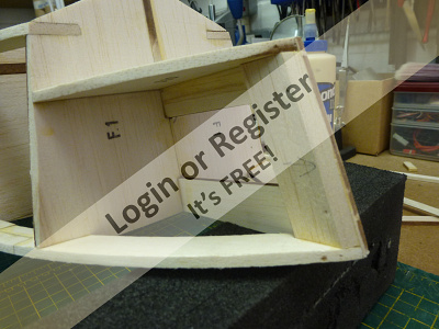
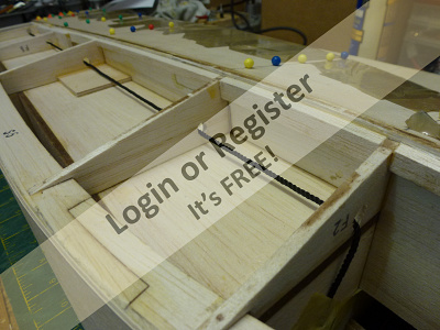
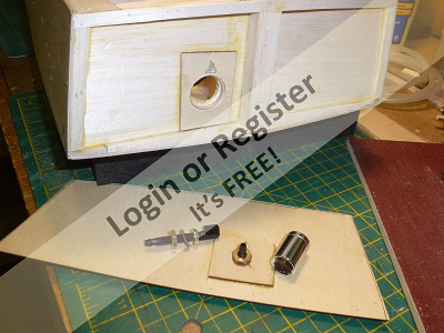
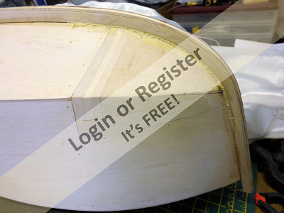
Various small pieces, S8 & S9, are added to bulkhead former F7 that create the curvature of the stern which in turn support the outer skin, in addition there are some pieces that are fixed either side of the keel as laminations to add strength and to support the bottom skins where they meet the keel.
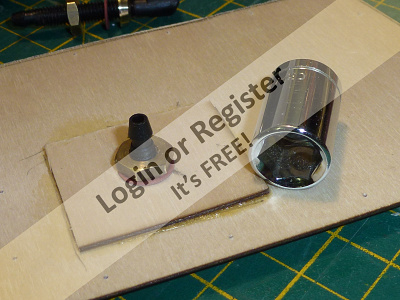
The prop shaft has yet to be delivered so I used a length of 8mm plastic rod temporarily in its place so that I could fit the keel laminations K5 around the shaft.
I chose to fit additional pieces on either side of the keel between the bulkhead formers to support the bottom skins and some extra pieces of balsa were fitted at the stern to support the outer skin, and in a similar fashion some extra pieces fitted either side of the keel formers at the prow.
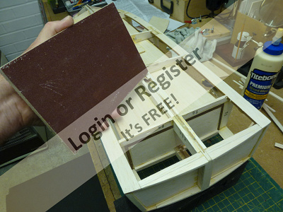
Once all these pieces were firmly set they need to sanded to the profile of the hull, and this is best done with abrasive paper around a sanding block. I made a sanding ‘plate’ from some 6mm MDF with a sheet of 120 grit aluminium oxide abrasive paper glued to it to form a perfectly flat sanding surface and this was used to chamfer and flatten the bulkhead, keel and chine formers so that the outer skins would lay as flat as possible across them.
I also fitted some pieces of ply under the centre section of the box around the keel to reinforce the area under where the motor mount will be as I don’t think the balsa base of the ‘box’ will take screws firmly.
The next step will be to fit the side skins and then the hull will really take shape.

The prop shaft has yet to be delivered so I used a length of 8mm plastic rod temporarily in its place so that I could fit the keel laminations K5 around the shaft.
I chose to fit additional pieces on either side of the keel between the bulkhead formers to support the bottom skins and some extra pieces of balsa were fitted at the stern to support the outer skin, and in a similar fashion some extra pieces fitted either side of the keel formers at the prow.
Once all these pieces were firmly set they need to sanded to the profile of the hull, and this is best done with abrasive paper around a sanding block. I made a sanding ‘plate’ from some 6mm MDF with a sheet of 120 grit aluminium oxide abrasive paper glued to it to form a perfectly flat sanding surface and this was used to chamfer and flatten the bulkhead, keel and chine formers so that the outer skins would lay as flat as possible across them.
I also fitted some pieces of ply under the centre section of the box around the keel to reinforce the area under where the motor mount will be as I don’t think the balsa base of the ‘box’ will take screws firmly.
The next step will be to fit the side skins and then the hull will really take shape.
▲
⟩⟩
stefan7964
Madwelshman
hmsnostalgia
Martin555
Geoffrhoose
BOATSHED
DaveWhittaker
octman
Sakibian
Missouri
Joe727
rolfman2000
RNinMunich
Donnieboy
mturpin013
|
💬 Stern & keel formers
5 years ago by 🇬🇧 rolfman2000 (
Warrant Officer)✧ 57 Views · 3 Likes
Flag
As Doug has said, thanks for some excellent tips and tricks. The hull is coming along nicely now, and I will assume that skinning is not far away now. Keeping my fingers crossed for one last update before Christmas. Thanks very much Robbob. Looking forward to the next chapter. Best wishes, Dave W 😊
▲
⟩⟩
BOATSHED
teejay
RNinMunich
|
|
Login To
Remove Ads 💬 Stern & keel formers
5 years ago by 🇩🇪 RNinMunich (
Fleet Admiral)✧ 53 Views · 1 Like
Flag
Good stuff Both, excellent tips n tricks 👍👍👍
▲
⟩⟩
BOATSHED
|
|
💬 Stern & keel formers
5 years ago by 🇬🇧 mturpin013 (
Admiral)✧ 56 Views · 4 Likes
Flag
I have found as you have that gluing your abrasive paper to a wooden block is far better than wrapping and making sure all the bulkheads and other skin supports are at the correct angle can make a real difference to the line of the hull, only noticeable when looking down the length of the hull when painted and that's too late to change things. I also make a number of different shaped sanding blocks/sticks down to using the coffee sticks with abrasives stuck to then for getting into difficult areas.
▲
⟩⟩
BOATSHED
Geoffrhoose
RNinMunich
Donnieboy
|
📝 Fitting the side skins.
5 years ago by 🇬🇧 robbob ( Admiral)
Admiral)✧ 66 Views · 19 Likes · 1 Comment
Flag
💬 Add Comment
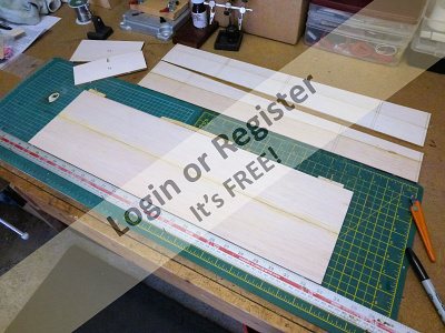
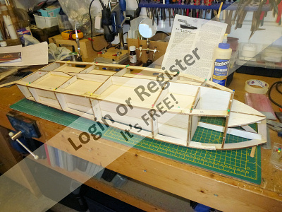
The side skins are made from 1.5mm ply and require a slight curve towards the bow and I found that this is best achieved by gently warming with a heat gun, which seems to relax the glue between the laminations, so that when bent to a gentle curve and allowed to cool will set the shape very easily.
The skins are supplied are slightly oversize and when the skins have been bent they can be roughly clamped to the hull and then marked for trimming, also while the skin is clamped in place the positions of the bulkhead formers can be marked on the skin.
Back on the bench the skins were trimmed with a craft knife (with a fresh blade) and then drilled with a 1mm bit to allow pinning through into the formers and strakes.
Aliphatic glue was applied to the hull formers and strakes and the skin positioned so that the drilled holes were in correct alignment with the formers and then clamped and pinned in place.
Because the skin was pre-formed to the hull shape the clamps and pins are not under much tension and the hull was set aside while the glue set.
When the port skin had fully set overnight, the pins and clamps were removed and the skin was finished with a plane to remove the excess down to the strakes and the F1 former at the bow and the sanding ‘plate’ used to finish it all off.
Where the side skins meet at the prow there needs to be a wide flat area for the external keel to butt to and so the trimming and sanding there will be done at a later stage before the bow blocks are fitted and carved.
The process was repeated for the starboard side skin and while the glue was setting I gave some thought to a means of concealing some of the wiring that needs to run the length of the hull 🤔.
▲
⟩⟩
stefan7964
Madwelshman
drspock
Martin555
Geoffrhoose
BOATSHED
JOHN
DaveWhittaker
octman
hmsnostalgia
Missouri
Nerys
mturpin013
Sakibian
Joe727
RNinMunich
rolfman2000
Donnieboy
Rookysailor
|
💬 Fitting the side skins.
5 years ago by 🇺🇸 Joe727 (
 Commander) Commander)✧ 55 Views · 3 Likes
Flag
Robbob,
Looking back again on some of your earlier posts, I see the plywood skinning that you did. I will be doing this on a future build as I am not the best at planking a hull. Your reference to HEATING THE PLYWOOD is a great tip, I have never tried that. Thanks, Joe ▲
⟩⟩
Martin555
BOATSHED
Donnieboy
|
📝 Internal wiring & bottom skins
5 years ago by 🇬🇧 robbob ( Admiral)
Admiral)✧ 70 Views · 16 Likes · 8 Comments
Flag
💬 Add Comment
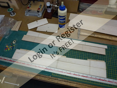
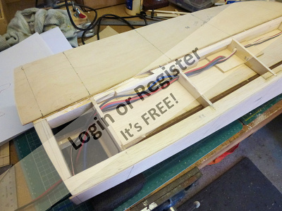
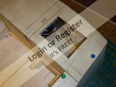
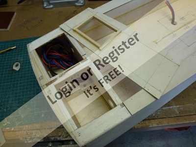
Because I am keen to conceal as much of the wiring as possible I have decided to place the battery at the bow and the operational equipment at the stern, the engine on the original boat was central and covered with a soundproof box and this is convenient as the motor can be positioned and concealed in the same way.
This means that some of the wires will have to run the full length of the boat and the easiest way to conceal them is to run them beneath the ‘box’ around which the hull is formed, and this needs to be done before the bottom skins are fitted.
Holes were bored through the bulkhead formers under the port side of the hull and battery cables were run to the stern where the ESC will be and three motor wires from the ESC run to the centre, emerging near the motor position.
For good measure I put in a servo cable and a separate draw wire just in case I needed to put more cabling in for any additional features, perhaps working navigation lights?
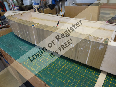
Satisfied that I had all the cabling in place I was able to fit the bottom skins starting with the starboard side first.
Before doing so I put a very slight 'hollow' in former F1 which should help blend the shape of the the hull where the ply skins meet the balsa blocks that will to be carved and shaped to form the bow.
This can be seen in the last picture.
The process of forming and fixing the skins is the same as for the side skins but in addition to the pins holding the skins in place I used some brown polythene ‘packing tape’ to pull the skins tightly against the bulkhead formers and strakes.
The packing tape has a very high tensile strength and is ideal for this, and of course cheap and easy to remove.
Once the aliphatic glue had set thoroughly overnight I removed the excess from the skins with a small block plane and finished them with my sanding plate.
Before I fit the skin at the stern I will have to arrange the water cooling for the ESC, with the pickup just behind the prop and the outlet on the stern.
I’ll cover that aspect in the next update.
This means that some of the wires will have to run the full length of the boat and the easiest way to conceal them is to run them beneath the ‘box’ around which the hull is formed, and this needs to be done before the bottom skins are fitted.
Holes were bored through the bulkhead formers under the port side of the hull and battery cables were run to the stern where the ESC will be and three motor wires from the ESC run to the centre, emerging near the motor position.
For good measure I put in a servo cable and a separate draw wire just in case I needed to put more cabling in for any additional features, perhaps working navigation lights?
Satisfied that I had all the cabling in place I was able to fit the bottom skins starting with the starboard side first.
Before doing so I put a very slight 'hollow' in former F1 which should help blend the shape of the the hull where the ply skins meet the balsa blocks that will to be carved and shaped to form the bow.
This can be seen in the last picture.
The process of forming and fixing the skins is the same as for the side skins but in addition to the pins holding the skins in place I used some brown polythene ‘packing tape’ to pull the skins tightly against the bulkhead formers and strakes.
The packing tape has a very high tensile strength and is ideal for this, and of course cheap and easy to remove.
Once the aliphatic glue had set thoroughly overnight I removed the excess from the skins with a small block plane and finished them with my sanding plate.
Before I fit the skin at the stern I will have to arrange the water cooling for the ESC, with the pickup just behind the prop and the outlet on the stern.
I’ll cover that aspect in the next update.
▲
⟩⟩
Madwelshman
hmsnostalgia
Ianh
Martin555
Geoffrhoose
BOATSHED
DaveWhittaker
octman
jacko
Missouri
mturpin013
Joe727
Donnieboy
figtree7nts
Rookysailor
rolfman2000
|
💬 Internal wiring & bottom skins
5 years ago by 🇬🇧 mturpin013 (
Admiral)✧ 62 Views · 4 Likes
Flag
Rob, if all is OK maybe you have proved different to the current thinking, I hope so, because as you know electrics is complicated enough without having to consider the length of the wire, I'm happy if the bulb lights up, that's an achievement!!
▲
⟩⟩
BOATSHED
DaveWhittaker
Sakibian
Donnieboy
|
|
Login To
Remove Ads 💬 Internal wiring & bottom skins
5 years ago by 🇬🇧 robbob (
Admiral)✧ 60 Views · 2 Likes
Flag
Hi Mike.
All the wiring is in place, it's not too late to alter it and the placements but it just creates more problems than it solves, I respect Alan's opinion and words of caution but I hope that his concerns are unfounded. I'll take the risk.😉 Rob. ▲
⟩⟩
hmsnostalgia
BOATSHED
|
|
💬 Internal wiring & bottom skins
5 years ago by 🇬🇧 mturpin013 (
Admiral)✧ 60 Views · 2 Likes
Flag
Hi Rob, I'm really pleased to see construction detail, I suppose in preference to a finished boat, you may ask why? well looking at your pictures, the last two in particular they show the precision of your woodworking skills with a distinct absence of any filler, really nice. Looking at the first picture (top view) is there any reason why the battery and ECS can't go in front and behind the motor addressing the issue of short wiring runs (not that I have a clue about wiring and electronics)
PS. however it looks like its too late as some wiring is already installed and by now the skins are probably on now Keep up the good work ▲
⟩⟩
BOATSHED
DaveWhittaker
|
|
💬 Internal wiring & bottom skins
5 years ago by 🇬🇧 robbob (
Admiral)✧ 60 Views · 3 Likes
Flag
Hi Alan.
Thanks for the cautionary comments. Placing the battery up front is the only practical location and I'm using 12 SWG wire so current handling won't be a problem but inductance could be a factor. I could fit a ferrite ring but that would only help to suppress any RF noise so there's not much more I can really do other than put the ESC up front too but that would mean re-plumbing the water cooling and the motor wires too. I'm gonna have to trust my luck on that score 🤞. Best Wishes. Rob. ▲
⟩⟩
Ianh
BOATSHED
hmsnostalgia
|
|
💬 Internal wiring & bottom skins
5 years ago by 🇬🇧 ukengineman (
 Leading Seaman) Leading Seaman)✧ 61 Views · 2 Likes
Flag
Hi Rob, the Police Launch is coming along nicely. I see that you have long leads from the battery to the ESC. The general rule is that these leads should be kept as short as possible to minimize voltage spikes caused by the fast switching currents and the inductance of the leads. Brushless ESC's have large capacitors, often visible at the end to absorb the transients. You may well get away with it but the life of the ESC could be reduced.
Hope your Xmas goes well, Alan ▲
⟩⟩
BOATSHED
RNinMunich
|
|
💬 Internal wiring & bottom skins
5 years ago by 🇬🇧 rolfman2000 (
Warrant Officer)✧ 66 Views · 1 Like
Flag
Thanks for that mate. I was just a bit worried about access space, and didn't realise how big the rear compartment is on this BIGGER police launch. Cheers, Dave W 😊
▲
⟩⟩
BOATSHED
|
|
💬 Internal wiring & bottom skins
5 years ago by 🇬🇧 robbob (
Admiral)✧ 66 Views · 10 Likes
Flag
There's plenty of access to fit the rudder tube at this stage because the deck skins have not gone on yet, and I still have fairly nimble fingers 🖖 😜
I'm generally following the kit instructions but I have sufficient experience to 'plot my own course' and deviate from them to achieve the same or better result. A great deal of thought and forward planning goes on when I build anything so I don't usually 'paint myself into a corner' so to speak. Here's a 'sneaky peek' (see pics) at the rudder and servo location that I'll cover in detail in the blog shortly. Happy Crimbo to you and yours 🎄 🎅 ⛄️ Robbob. 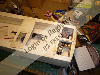
▲
⟩⟩
Madwelshman
Ianh
Martin555
BOATSHED
Geoffrhoose
DaveWhittaker
hmsnostalgia
RNinMunich
rolfman2000
figtree7nts
|
|
💬 Internal wiring & bottom skins
5 years ago by 🇬🇧 rolfman2000 (
Warrant Officer)✧ 65 Views · 1 Like
Flag
Hi Robbob, it's great to watch this coming along space, and the hull seems nearly there. But I notice no mention of the rudder post being fitted, and now the bottom skins are in place, the access has just gotten a whole lot harder. is this "as per the instructions" ? Or your own decision made from experience ? I'm afraid I would have at least fitted the rudder tube, as my rather large hands will have a hard time getting in later on. Kindest wishes to you and yours for the Christmas season, and a prosperous New Year, from UK family Weaver 😊
▲
⟩⟩
BOATSHED
|
📝 Plumbing the water-cooling for the ESC
5 years ago by 🇬🇧 robbob ( Admiral)
Admiral)✧ 69 Views · 13 Likes
Flag
💬 Add Comment
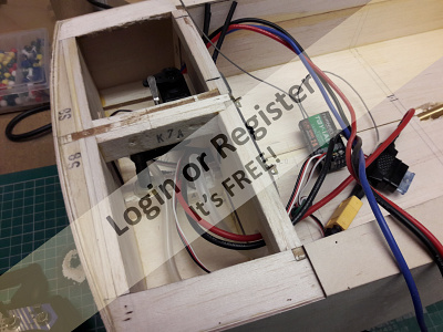
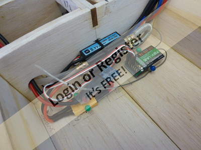
The HobbyKing ESC I’m using has the facility for water cooling and as it will be in an enclosed location without any free ventilation it seems sensible to utilise this feature.
To keep the water circuit as short as possible I will put the pickup just behind the propeller and the exhaust on the stern but as the boat has a bulkhead just in front of the stern skin I need to make an access hole through it to allow me to secure the nut on the stern skin.
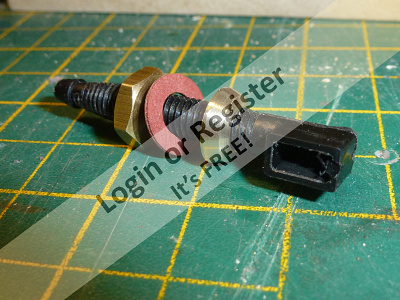
I made a hole through the bulkhead large enough to get a socket on the nut and reinforced the hole with a ply plate, similarly I reinforced the inside of the stern skin where the outlet passes through it.
When I was happy that the arrangement worked and I could attach the hoses and securing clips easily I glued and pinned the stern skin to the hull.
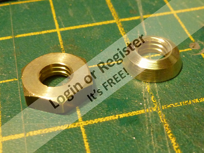
The water pickup is a standard one that is readily available but it’s supplied with overly large and ugly fixing nuts, the inside one is of no consequence but I thought that the outer one needed smartening up so I put it on a threaded rod and locked it in place with another nut and put that into the chuck of a drill and used a file to re-shape the nut to a pleasing taper….who needs a lathe......😜
I had to reduce the height of the inner keel former as the pickup tube is not long enough to get a good fixing with the internal nut, as the inner keel is balsa I fitted a ply reinforcing plate to spread the load.
The last ‘photo shows the location of the ESC, main battery fuse and receiver. The hoses will be secured to the ESC with spring clips throughout.
I found that the silicone tube I use tends to kink rather easily if the radius of a bend is too small and I found it necessary to form a tight spring coil around the piece that loops the water back through the ESC to prevent this happening.


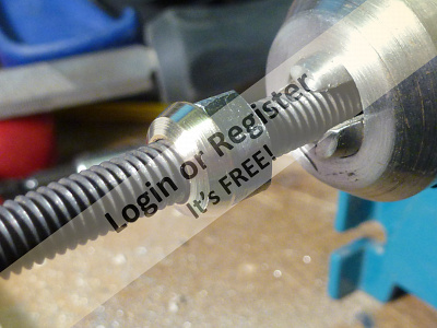
To keep the water circuit as short as possible I will put the pickup just behind the propeller and the exhaust on the stern but as the boat has a bulkhead just in front of the stern skin I need to make an access hole through it to allow me to secure the nut on the stern skin.
I made a hole through the bulkhead large enough to get a socket on the nut and reinforced the hole with a ply plate, similarly I reinforced the inside of the stern skin where the outlet passes through it.
When I was happy that the arrangement worked and I could attach the hoses and securing clips easily I glued and pinned the stern skin to the hull.
The water pickup is a standard one that is readily available but it’s supplied with overly large and ugly fixing nuts, the inside one is of no consequence but I thought that the outer one needed smartening up so I put it on a threaded rod and locked it in place with another nut and put that into the chuck of a drill and used a file to re-shape the nut to a pleasing taper….who needs a lathe......😜
I had to reduce the height of the inner keel former as the pickup tube is not long enough to get a good fixing with the internal nut, as the inner keel is balsa I fitted a ply reinforcing plate to spread the load.
The last ‘photo shows the location of the ESC, main battery fuse and receiver. The hoses will be secured to the ESC with spring clips throughout.
I found that the silicone tube I use tends to kink rather easily if the radius of a bend is too small and I found it necessary to form a tight spring coil around the piece that loops the water back through the ESC to prevent this happening.
▲
⟩⟩
Madwelshman
Martin555
Geoffrhoose
BOATSHED
DaveWhittaker
octman
hmsnostalgia
Joe727
Missouri
mturpin013
Donnieboy
figtree7nts
rolfman2000
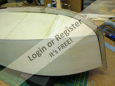
📝 Decks & hatches.
5 years ago by 🇬🇧 robbob ( Admiral)
Admiral)✧ 70 Views · 13 Likes · 5 Comments
Flag
💬 Add Comment
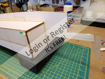
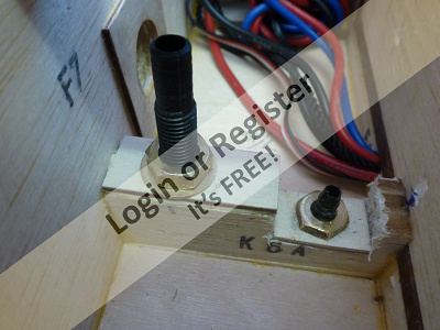
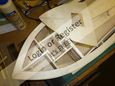
Because I need access to the wiring at both ends of the boat I formed the framework of an opening at the bow to make the dummy hatch into a real hatch.
In a similar way a hatch was formed in the rear deck which will give me access to the wiring, rudder servo and the ESC cooling.
It’s going to be quite tight to get all that into the cavity under the rear deck but I’ve done a test fit and it will all go in but will involve some ‘keyhole surgery’ through the rear hatch opening when I get to the stage of installing all of the running gear…🤓.
Both of these decks were glued and pinned in place and some packing tape used to pull the decks firmly onto the frames.
The side decks were also trimmed for best fit and secured in the same way and when all was dry and set a small hand plane was used to trim them flush to the hull sides.
The next stage will be to fit the balsawood blocks at the bow and shape them to the hull…..it’s the tricky bit I’ve not been looking forward to…😟
▲
⟩⟩
Madwelshman
hmsnostalgia
Martin555
Geoffrhoose
BOATSHED
DaveWhittaker
octman
Joe727
RNinMunich
rolfman2000
Missouri
figtree7nts
Donnieboy
|
💬 Re: Decks & hatches.
4 years ago by 🇬🇧 drspock (
 Petty Officer 1st Class) Petty Officer 1st Class)✧ 58 Views · 0 Likes
Flag
Hi Rob,
Only just seen this.Will look into how you did it. Many thanks. Doc. ▲
⟩⟩
No likes yet
This member will receive 1 point for every like received |
|
Login To
Remove Ads 💬 Re: Decks & hatches.
4 years ago by 🇬🇧 robbob (
Admiral)✧ 60 Views · 2 Likes
Flag
Hi Doc.
The battery is actually installed within 'the box' and is hidden inside a separate box that forms the control panel and steering wheel. You will see later in my blog how I did this. The wires from the battery and 'steering wheel' power switch do run beneath the floor to the stern and connect to the fuse and ESC. Mike Turpin (mturpin013)has very cleverly installed some 'conduits' in his boat that will make running the wires through much easier, something that I wished I'd thought of 🤔 Rob. ▲
⟩⟩
Martin555
hmsnostalgia
|
|
💬 Re: Decks & hatches.
4 years ago by 🇬🇧 drspock (
Petty Officer 1st Class)✧ 59 Views · 2 Likes
Flag
Hi Rob,
Can you confirm that you installed the battery in the bow beneath your hatch cover,with the wiring running inside the bottom skins? I had thought of adding a removable false panel to F2, to accommodate it. Cheers, Doc ▲
⟩⟩
Martin555
robbob
|
|
💬 Decks & hatches.
5 years ago by 🇬🇧 robbob (
Admiral)✧ 63 Views · 5 Likes
Flag
Forward planning is essential to me and that's probably why it takes me so long to build stuff, about 75% thinking about it and 25% doing it!
Ever heard of the 6 P's ? Propper Planning Prevents P*** Poor Performance Or..'Failing to plan is planning to fail' I still make mastakes though...lots 😜 Edit: Just seen my typo above...oops. ▲
⟩⟩
hmsnostalgia
BOATSHED
Geoffrhoose
figtree7nts
RNinMunich
|
|
💬 Decks & hatches.
5 years ago by 🇬🇧 mturpin013 (
Admiral)✧ 61 Views · 3 Likes
Flag
Forward thinking, that's a must for this hobby as you can always guarantee that the designers don't always think of everything. (I suppose that's why VM have asked you to trial it)
Its looking good, I always like seeing the build details as hidden construction is not always appreciated when the boat is complete. ▲
⟩⟩
BOATSHED
DaveWhittaker
Donnieboy
|
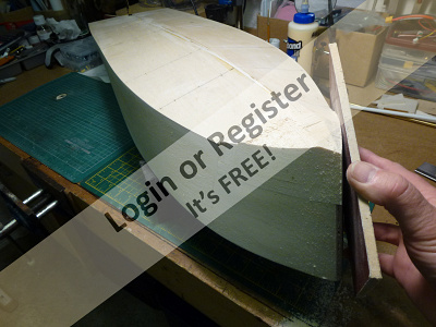
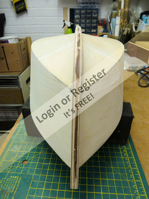
📝 The bow blocks & outer keel
5 years ago by 🇬🇧 robbob ( Admiral)
Admiral)✧ 69 Views · 13 Likes · 6 Comments
Flag
💬 Add Comment
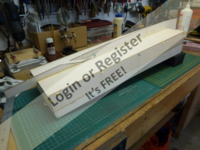
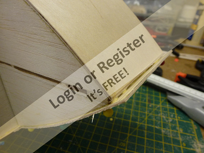
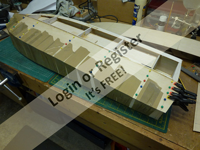
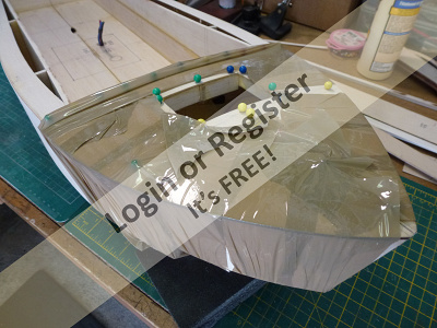
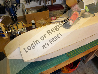
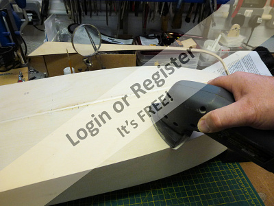
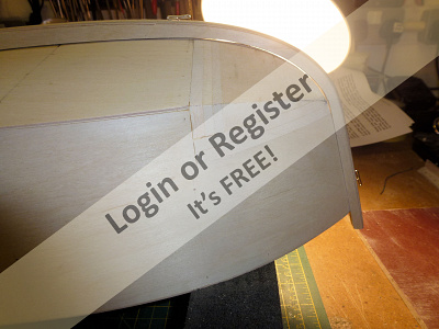
The bow of the boat has a compound curve and to create the shape a single block of hard balsa is supplied in the kit, although in my pre-production prototype this had to be formed by laminating some pieces of thick balsa together to the required size.
Rather than laminating up a single block separately I did the laminating and glueing in situ on the hull to ensure a solid tight block, and after the glue had cured I set about shaping it.
Initially I used a razor saw to roughly remove the surplus at the sides and bottom and then began the process of shaping it to the final form. My sanding plate proved invaluable for the final stages of making the block flush with the hull sides.
The underside of the blocks were very carefully shaped with a combination of the sanding plate and abrasive paper around a series large round formers.
I was careful not to just use abrasive paper over fingers as this can create grooves and unevenness in the soft balsa. I had already created a concave shape in the bulkhead former F1 and with the ply bottom skins in place it was relatively easy to extend the contour into the bow blocks being very careful to ensure symmetry on both sides.
A line was drawn on the blocks that extended the curve of the hull strakes to define the shape.
I also used the outer keel as a template throughout the shaping process to make sure that I was not removing too much material. it would be very easy to remove too much material so it pays to do this slowly and carefully, checking all the time for symmetry.
Finally when I was happy with the shape I formed a slight flat on the blocks for the outer keel to sit on, using a back light helped greatly with this, and the whole hull was given a light sanding with a detail sander.
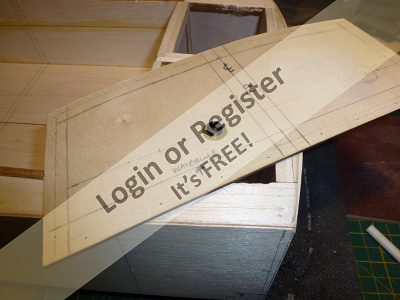
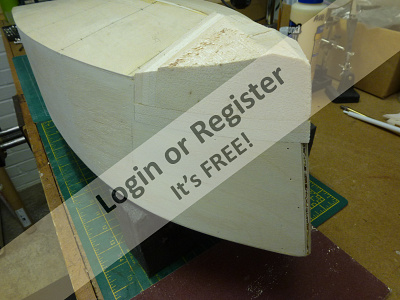
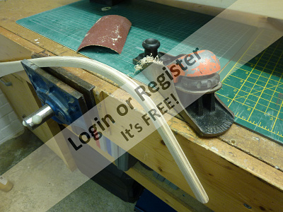
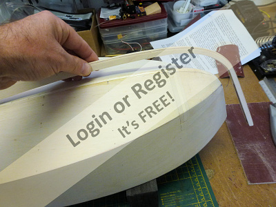
The prototype kit was supplied with keel components made from thick balsa which would easily be damaged in use so I recreated this in thick ply laminations to the required thickness and shaped it so that it was completely flat and square on the inner edges and with a curved profile on its outer edges.
The keel was checked for fit on the hull throughout so that only a minimum amount of filler would be required to blend it to the hull.
It was fixed in place with epoxy adhesive and firmly pinned until it fully set and very little filler used to finish it.
The kit, which is available now from VMW, includes a single piece bow block and ply keel parts as standard, which makes construction much quicker and easier.
I’m glad that bit is over and I’m very pleased with the result.
Next stage will be glass fibre cloth and epoxy resin….
Rather than laminating up a single block separately I did the laminating and glueing in situ on the hull to ensure a solid tight block, and after the glue had cured I set about shaping it.
Initially I used a razor saw to roughly remove the surplus at the sides and bottom and then began the process of shaping it to the final form. My sanding plate proved invaluable for the final stages of making the block flush with the hull sides.
The underside of the blocks were very carefully shaped with a combination of the sanding plate and abrasive paper around a series large round formers.
I was careful not to just use abrasive paper over fingers as this can create grooves and unevenness in the soft balsa. I had already created a concave shape in the bulkhead former F1 and with the ply bottom skins in place it was relatively easy to extend the contour into the bow blocks being very careful to ensure symmetry on both sides.
A line was drawn on the blocks that extended the curve of the hull strakes to define the shape.
I also used the outer keel as a template throughout the shaping process to make sure that I was not removing too much material. it would be very easy to remove too much material so it pays to do this slowly and carefully, checking all the time for symmetry.
Finally when I was happy with the shape I formed a slight flat on the blocks for the outer keel to sit on, using a back light helped greatly with this, and the whole hull was given a light sanding with a detail sander.
The prototype kit was supplied with keel components made from thick balsa which would easily be damaged in use so I recreated this in thick ply laminations to the required thickness and shaped it so that it was completely flat and square on the inner edges and with a curved profile on its outer edges.
The keel was checked for fit on the hull throughout so that only a minimum amount of filler would be required to blend it to the hull.
It was fixed in place with epoxy adhesive and firmly pinned until it fully set and very little filler used to finish it.
The kit, which is available now from VMW, includes a single piece bow block and ply keel parts as standard, which makes construction much quicker and easier.
I’m glad that bit is over and I’m very pleased with the result.
Next stage will be glass fibre cloth and epoxy resin….
▲
⟩⟩
Madwelshman
Martin555
Geoffrhoose
Missouri
DaveWhittaker
octman
hmsnostalgia
mturpin013
Joe727
BOATSHED
figtree7nts
Donnieboy
rolfman2000
|
💬 The bow blocks & outer keel
5 years ago by 🇬🇧 cenbeth (
 Chief Petty Officer 1st Class) Chief Petty Officer 1st Class)✧ 72 Views · 1 Like
Flag
I read somewhere that if you diagonally plank a hull that can give you concave hulls. I have never done this but would be interested to hear from people who have.
▲
⟩⟩
Madwelshman
|
|
Login To
Remove Ads 💬 The bow blocks & outer keel
5 years ago by 🇬🇧 robbob (
Admiral)✧ 61 Views · 3 Likes
Flag
Michael.
I think the reason for the balsa block method is that you can really only bend ply in one plane effectively, to produce the bow shape of this boat would entail the ply being contorted in two planes, one concave and one convex, to form the compound curve and even with thin 1.5mm ply you just can't do that easily. The crash tender bow is just a convex bend. Thus the balsa block method becomes the only way to achieve the shape and to be honest it's not that difficult to do with care and patience. ▲
⟩⟩
hmsnostalgia
BOATSHED
RNinMunich
|
|
💬 The bow blocks & outer keel
5 years ago by 🇬🇧 mturpin013 (
Admiral)✧ 59 Views · 1 Like
Flag
Missed this one yesterday! what a credit to your workmanship a brilliant job. Your decision to replace the keel with ply I think was a good one, balsa although it would be glassed would still not be as strong.
Not seeing the boat in real life can I ask the question why they decided to use a block rather than curving the ply skins round as the crash tender is. Although skinning may be more difficult, the end profile is a given, but having to profile a balsa block I would suggest is more difficult. Any thoughts? not having done a balsa bow myself ▲
⟩⟩
BOATSHED
|
|
💬 The bow blocks & outer keel
5 years ago by 🇬🇧 robbob (
Admiral)✧ 60 Views · 3 Likes
Flag
Hi samc.
I'm just writing the blog entry for the hull glassing process and I'll detail the material and process, it's very much the same as the I did on my 46" RAF Crash Tender blog, see here: ▲
⟩⟩
Madwelshman
BOATSHED
hmsnostalgia
|
|
💬 The bow blocks & outer keel
5 years ago by 🇺🇸 samc (
 Master Seaman) Master Seaman)✧ 62 Views · 0 Likes
Flag
hello i'm trying to epoxy finish on my dumas CC commander and having a hard time getting a smooth surface each time try to put on a coat. it comes out wavy and not even. have tried foam and reg brushes, auto body spreader, try a foam roller, better it was even but not smooth
any hints would be helpfully... samc ▲
⟩⟩
No likes yet
This member will receive 1 point for every like received |
|
💬 The bow blocks & outer keel
5 years ago by 🇬🇧 rolfman2000 (
Warrant Officer)✧ 68 Views · 2 Likes
Flag
This was the part I had been waiting for. As I was only 12 when I made mine, my Uncle Cyril was given the job of shaping, and he made a right pigs arse out of it. I had to do a lot of filling and sanding to correct it. I notice you had the "glad it's over" reaction. I reckon my reaction will be very similar. Thanks for sharing Robbob. 😊
▲
⟩⟩
Geoffrhoose
BOATSHED
|


Login To
Remove Ads
Remove Ads