Join Us On Social Media!

|

|

|
Download The App!
Login To
Remove Ads
Remove Ads
Login To
Remove Ads
Remove Ads
Model Boats Website
HAKITS- PILOT LAUNCH-LARGER VERSION.
12 Posts · 6 Followers · 83 Photos · 82 Likes
Began 3 years ago by
 United Kingdom
Follow This Thread
Not currently following
> Click to follow
> Click to follow
Latest Post 3 years ago by
| Oldest posts shown first (Show Newest First) | (Print Booklet) |
📝 HAKITS- PILOT LAUNCH-LARGER VERSION.
3 years ago by 🇬🇧 mistyoptic ( Midshipman)
Midshipman)✧ 116 Views · 12 Likes · 8 Comments
Flag
💬 Add Comment
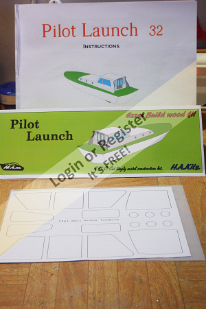
HAKITS -PILOT LAUNCH - LARGER VERSION.
No sooner had the paint dried on my HAkits Morston, the kit for the Pilot Launch arrived.
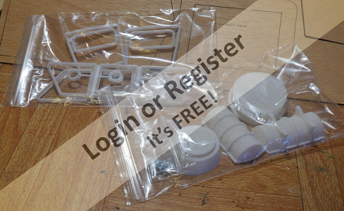
Simply but securely packed, the outer corrugated cardboard wrapping revealed the contents of the entire kit in a polythene sleeve, simply bound at the top with a folded and stapled printed name.
No fancy expensive box to add to the cost, the laser cut sheets were a snug fit in the sleeve and included were the 3D printed window frames, a radar scanner and a life-raft, the Handbook and a printed template for the window shapes and the acetate sheet to use with them, and that was that. If you are new to HA Kits then you might have been disappointed in what you have got, but from my point of view as someone who loves working with wood, I knew that from experience of the Morston, the kit would deliver a good deal of satisfaction and an opportunity for me to try some different ways of doing things.
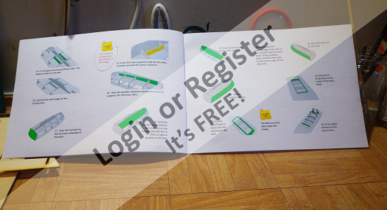
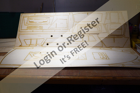
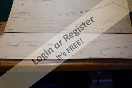
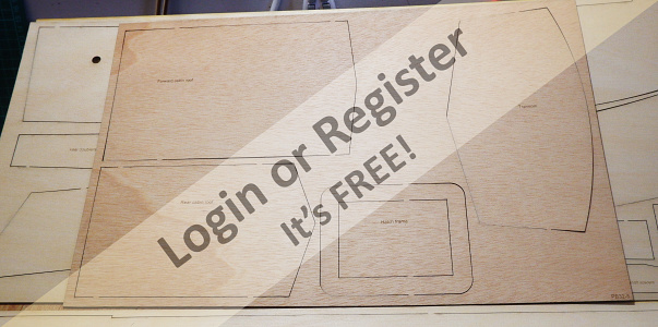
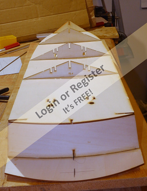
Taking the ply sheets from the wrapper I could see that the wood was of good quality and the laser cutting precise, and most parts etched with their title, smaller parts were named on the waste wood immediately adjacent to the part. And talking of waste wood, a useful by product of this type of kit is that you get a good selection of bits of ply to use elsewhere or for making other bits for the model, if nothing else, a good selection of paint stirring and epoxy mixing sticks to see you through this model and the next. However, the way the parts are laid out does make economical use of the raw material. The handbook says to read it through before starting and to remove all parts form the sheets of ply. I cannot emphasise this too much, it is essential to do this, just so that you gain an idea of what each part looks like and to be familiar with the suggested order of assembly, and you will soon find the merit in this as you start to put things together.
The handbook suggests using CA glue for building, but I would not be able to use such an amount of that glue because it irritates my eyes and nasals. So, I am using Gorilla wood glue, this may not be totally waterproof but is not going to get that wet, I hope. Over the years of building model aircraft I have adopted a way of using PVA glue efficiently. I decant the glue into a small pot, breakfast jam jar or a hand cream jar, so that I am not having to dip in the glue container, as the smaller amount is available. I have a selection of cheap artist brushes, Poundland and the like, in a jar with water and when gluing is required, I just take a brush, wipe off the excess water, dip it in the little glue pot and brush onto the parts. Chose brushes with non-rust ferrules, most have aluminium.
It would be easy to push ahead with the building of this model, following the handbook and then later when the running gear needed to be fitted you will have backed yourself into a corner, so I suggest take it slowly, one step at a time and make sure that before you proceed to the next step, by doing so you will not make life difficult later.
The Model is based on the Hartlepool Pilot Boat Crusader of the 1970’s and is designed for twin motors and rudders. I have chosen two brushless motors rated at 140w each and the prop shaft length as recommended in the handbook. I have not chosen mega power in this case as the Woodbridge pond is quite small and so a potentially high speed will not be achievable, so a good speed will be satisfactory.
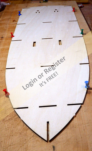
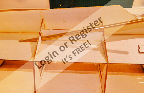
So, the build starts with placing the lower deck on a board, and then fitting the formers to this. There are pics here showing how accurately cut these parts are and they go together quite easily, checking for squareness as I go. This is the first step so more next time. Geoff.


No sooner had the paint dried on my HAkits Morston, the kit for the Pilot Launch arrived.
Simply but securely packed, the outer corrugated cardboard wrapping revealed the contents of the entire kit in a polythene sleeve, simply bound at the top with a folded and stapled printed name.
No fancy expensive box to add to the cost, the laser cut sheets were a snug fit in the sleeve and included were the 3D printed window frames, a radar scanner and a life-raft, the Handbook and a printed template for the window shapes and the acetate sheet to use with them, and that was that. If you are new to HA Kits then you might have been disappointed in what you have got, but from my point of view as someone who loves working with wood, I knew that from experience of the Morston, the kit would deliver a good deal of satisfaction and an opportunity for me to try some different ways of doing things.
Taking the ply sheets from the wrapper I could see that the wood was of good quality and the laser cutting precise, and most parts etched with their title, smaller parts were named on the waste wood immediately adjacent to the part. And talking of waste wood, a useful by product of this type of kit is that you get a good selection of bits of ply to use elsewhere or for making other bits for the model, if nothing else, a good selection of paint stirring and epoxy mixing sticks to see you through this model and the next. However, the way the parts are laid out does make economical use of the raw material. The handbook says to read it through before starting and to remove all parts form the sheets of ply. I cannot emphasise this too much, it is essential to do this, just so that you gain an idea of what each part looks like and to be familiar with the suggested order of assembly, and you will soon find the merit in this as you start to put things together.
The handbook suggests using CA glue for building, but I would not be able to use such an amount of that glue because it irritates my eyes and nasals. So, I am using Gorilla wood glue, this may not be totally waterproof but is not going to get that wet, I hope. Over the years of building model aircraft I have adopted a way of using PVA glue efficiently. I decant the glue into a small pot, breakfast jam jar or a hand cream jar, so that I am not having to dip in the glue container, as the smaller amount is available. I have a selection of cheap artist brushes, Poundland and the like, in a jar with water and when gluing is required, I just take a brush, wipe off the excess water, dip it in the little glue pot and brush onto the parts. Chose brushes with non-rust ferrules, most have aluminium.
It would be easy to push ahead with the building of this model, following the handbook and then later when the running gear needed to be fitted you will have backed yourself into a corner, so I suggest take it slowly, one step at a time and make sure that before you proceed to the next step, by doing so you will not make life difficult later.
The Model is based on the Hartlepool Pilot Boat Crusader of the 1970’s and is designed for twin motors and rudders. I have chosen two brushless motors rated at 140w each and the prop shaft length as recommended in the handbook. I have not chosen mega power in this case as the Woodbridge pond is quite small and so a potentially high speed will not be achievable, so a good speed will be satisfactory.
So, the build starts with placing the lower deck on a board, and then fitting the formers to this. There are pics here showing how accurately cut these parts are and they go together quite easily, checking for squareness as I go. This is the first step so more next time. Geoff.
▲
⟩⟩
nasraf
Colin H
jacko
jbkiwi
Ianh
Razor1955
robbob
Martin555
Seanympth
Ygagnon
Rookysailor
RNinMunich
|
💬 Re: HAKITS- PILOT LAUNCH-LARGER VERSION.
3 years ago by 🇮🇪 billmcl61 (
 Warrant Officer) Warrant Officer)✧ 84 Views · 2 Likes
Flag
Hi Geoff,
Many thanks for coming back so quickly. Ah, pity although I did think that the SLA batteries might be a bit of a squeeze. I think I will give one of these a bash, they look like an interesting and fun build. I'll drop Hakits a mail tomorrow and ask them a few things. Regards Bill ▲
⟩⟩
Seanympth
Martin555
|
|
Login To
Remove Ads 💬 Re: HAKITS- PILOT LAUNCH-LARGER VERSION.
3 years ago by 🇬🇧 mistyoptic (
Midshipman)✧ 88 Views · 3 Likes
Flag
Hello and thank you for your comment. I am not sure that 2 6v SLA would fit comfortably in the Morston, it would need to be the larger version and the equipment space in that model is situated under the hatch at the font of the boat and too much extra weight there would give an imbalance in the water. There is much more headroom in the Pilot Launch and the equipment space is toward the back of the boat but this is a twin-engined model and you may not want to tackle this just now. If you want a definite answer please e mail HAkits they will be pleased to advise. or simply buy a smaller Lipo or Nimh battery.
Best wishes Geoff. ▲
⟩⟩
billmcl61
Martin555
Seanympth
|
|
💬 Re: HAKITS- PILOT LAUNCH-LARGER VERSION.
3 years ago by 🇮🇪 billmcl61 (
Warrant Officer)✧ 89 Views · 3 Likes
Flag
Hi Geoff,
I'm glad that you've done another blog, I really enjoyed the last one, I've yet to build a boat, my woodworking skills still need to be refined shall we say 😊, however, I still have a sizable box of bits that I bought for my pusher tug (might have another attempt in spring) which I would like to use in another build, but one that I stand a chance of completing, and I was wondering how much space height wise is available in the Hakits boats, I have 2 6V SLA batteries that I would like to use but they are a bit chunky, could you let me know how much space is available inside the hulls please. Many thanks Bill ▲
⟩⟩
Seanympth
Martin555
mistyoptic
|
|
💬 Re: HAKITS- PILOT LAUNCH-LARGER VERSION.
3 years ago by 🇿🇦 Ianh (
 Commander) Commander)✧ 98 Views · 3 Likes
Flag
Well written and thought out
Regards Ian ▲
⟩⟩
Seanympth
Martin555
mistyoptic
|
|
💬 Re: HAKITS- PILOT LAUNCH-LARGER VERSION.
3 years ago by 🇬🇧 mistyoptic (
Midshipman)✧ 93 Views · 2 Likes
Flag
Thanks for your encouragement Treve, am pressing on while the snow continues to fall on Suffolk.
Regards Geoff ▲
⟩⟩
Seanympth
Martin555
|
|
💬 Re: HAKITS- PILOT LAUNCH-LARGER VERSION.
3 years ago by 🇬🇧 Seanympth (
 Chief Petty Officer 2nd Class) Chief Petty Officer 2nd Class)✧ 97 Views · 2 Likes
Flag
Beautifully written, many thanks for sharing your experience, looking forward to following this build. Thank you for taking the time to share your build and advice, I am looking forward to following this build.
Best wishes Treve ▲
⟩⟩
Martin555
mistyoptic
|
|
💬 Re: HAKITS- PILOT LAUNCH-LARGER VERSION.
3 years ago by 🇬🇧 mistyoptic (
Midshipman)✧ 98 Views · 2 Likes
Flag
Martin, Thanks for your comment and interest, I am really looking forward to this build and will be introducing some of my own ideas to enhance(?) the model, I do like to do some things differently from the norm. possibly will build the whole range if locked in much longer!
Geoff ▲
⟩⟩
Seanympth
Martin555
|
|
💬 Re: HAKITS- PILOT LAUNCH-LARGER VERSION.
3 years ago by 🇬🇧 Martin555 (
 Fleet Admiral) Fleet Admiral)✧ 99 Views · 2 Likes
Flag
Hi Misty,
I followed your last build and you did a fantastic job on that one and I am interested in this one as well. As you say the kit looks basic. It looks like a lot of effort has been put in to the instructions. Will you planning on working your magic on building the hole range of boats that HAKITS make LOL!! Martin555. ▲
⟩⟩
Seanympth
mistyoptic
|
Login To
Remove Ads
Remove Ads
📝 HAKITS- PILOT LAUNCH-LARGER VERSION.
3 years ago by 🇬🇧 mistyoptic ( Midshipman)
Midshipman)✧ 89 Views · 7 Likes · 1 Comment
Flag
💬 Add Comment
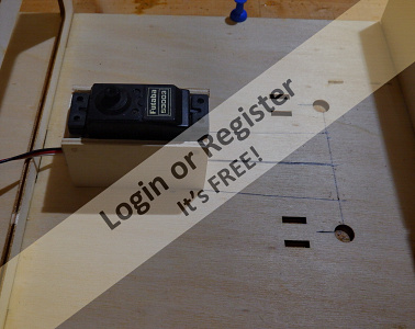
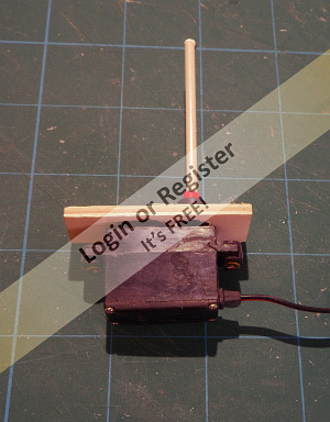
Thinking about the twin Rudders.
The first part of the build had been done, the deck pinned to the board and the formers added, checking all securely glued and at right angles to the deck. The next step is to remove the structure from the board and glue on the upper deck, but I wanted to make sure that the twin rudders would work efficiently and smoothly. I had selected, from stock, a Futaba standard servo, which would power both rudders using a push pull movement. The servo to be mounted vertically because there is ample room to do this, in fact this boat is so roomy you can almost get inside and walk around.
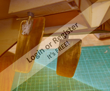
I have chosen to make my own rudders and rudder tubes because the height of a commercial rudder would possibly not be high enough to reach the level of the servo top. More of this later. So, to take advantage of the top deck not yet being fitted, I made a mock-up with balsa and fixed the servo arm to this and the rudders arms just to make sure that the geometry of the push pull arrangement would work, and it did. A servo box was then made from ply and using a surround stuck this to the lower deck with epoxy. Obviously, it will be necessary to ensure accuracy in fitting all this in place, so the deck was marked and measured. I have arranged for the distance from the pivot of the rudder arm to the linkage hole, to be identical with the pivot to link hole on the servo so a 1:1 gearing is applied. The extender to the servo arm is cut from PC Circuit Board as are the rudder arms with a brass collet soldered to the copper side. I am just about ready to take the structure off the board and fit the upper deck. I include a pic of my glue pot arrangement as mentioned in last blog.
Geoff.


The first part of the build had been done, the deck pinned to the board and the formers added, checking all securely glued and at right angles to the deck. The next step is to remove the structure from the board and glue on the upper deck, but I wanted to make sure that the twin rudders would work efficiently and smoothly. I had selected, from stock, a Futaba standard servo, which would power both rudders using a push pull movement. The servo to be mounted vertically because there is ample room to do this, in fact this boat is so roomy you can almost get inside and walk around.
I have chosen to make my own rudders and rudder tubes because the height of a commercial rudder would possibly not be high enough to reach the level of the servo top. More of this later. So, to take advantage of the top deck not yet being fitted, I made a mock-up with balsa and fixed the servo arm to this and the rudders arms just to make sure that the geometry of the push pull arrangement would work, and it did. A servo box was then made from ply and using a surround stuck this to the lower deck with epoxy. Obviously, it will be necessary to ensure accuracy in fitting all this in place, so the deck was marked and measured. I have arranged for the distance from the pivot of the rudder arm to the linkage hole, to be identical with the pivot to link hole on the servo so a 1:1 gearing is applied. The extender to the servo arm is cut from PC Circuit Board as are the rudder arms with a brass collet soldered to the copper side. I am just about ready to take the structure off the board and fit the upper deck. I include a pic of my glue pot arrangement as mentioned in last blog.
Geoff.
▲
⟩⟩
Colin H
jbkiwi
Seanympth
Ianh
jacko
Martin555
Skydive130
|
💬 Re: HAKITS- PILOT LAUNCH-LARGER VERSION.
3 years ago by 🇬🇧 Martin555 (
Fleet Admiral)✧ 84 Views · 0 Likes
Flag
Hi Geoff,
Making the rudder horns and linkages has saved you money and you have the satisfaction of making them yourself. Keep up the good work. Martin555. ▲
⟩⟩
No likes yet
This member will receive 1 point for every like received |
📝 HAKITS- PILOT LAUNCH-LARGER VERSION.
3 years ago by 🇬🇧 mistyoptic ( Midshipman)
Midshipman)✧ 91 Views · 8 Likes · 4 Comments
Flag
💬 Add Comment
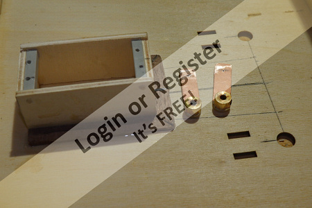
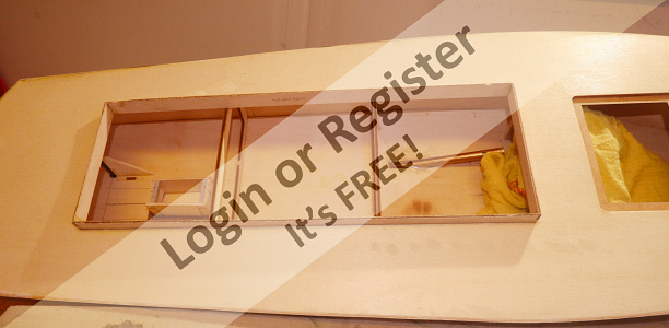
The Twin Rudders continued.
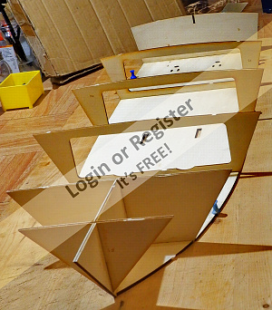
Since last time I have removed the deck from the board with formers attached and turned it over and fitted the upper deck, a straightforward task. As the formers have curved tops it is essential to make sure that the deck is glued to them across the whole width so that the deck takes on the same curvature, making sure that the deck meets and is securely glued to the outer points of the formers, also make sure that the deck is fitted centrally on the formers, this can be checked along the formers to ensure that it is placed centrally. I also marked the centre of the deck to ensure that it fitted centrally at the last former. I had pinned the centre of the deck to the bow former so that it stayed put while the rest of the deck was lined up. I must say that the accuracy of the parts of this model and the way they fit together does help in keeping the builders work accurate and furthermore it seems to demand accuracy from the builder, acting as a mentor in its own way.
With the hull now upside down on the deck, I have started to use a slab of plastic foam under the hull, firstly to give it a bit of stability on account of the curved deck and also to protect the deck from bruising by chippings or anything else that may be on the bench.
The lower formers were now glued in place, simply done and it was time to think about how the twin rudders would work to my own arrangement. I have devised my own way of building the rudder and linkage assembly because I have the time to do this, but the components mentioned in the handbook will be adequate and work well, so if you are pushed for time with an impatient son or grandson waiting by your elbow, then use the commercial components.
As I mentioned in the last entry, I have planned to use a Futaba standard servo mounted in an upright position and working a push pull action on the rudders with their arms facing inwards. A test run had proved that this should work.
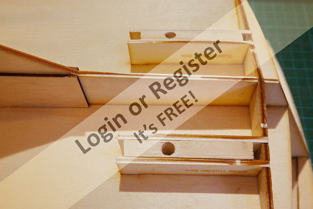
So, it was now a question of mounting the rudder tubes and rudders into the hull. In the kit, a former is placed in the lower side of the hull either side of the hole where the rudder is to be fixed. The holes are already cut in the lower deck and the outer hull skin so again all lines up easily. These formers were used, and I made up a softwood spacer with a 6mm hole drilled vertically to line up with the hole in the deck and put the formers in place and glued with the spacer in between.
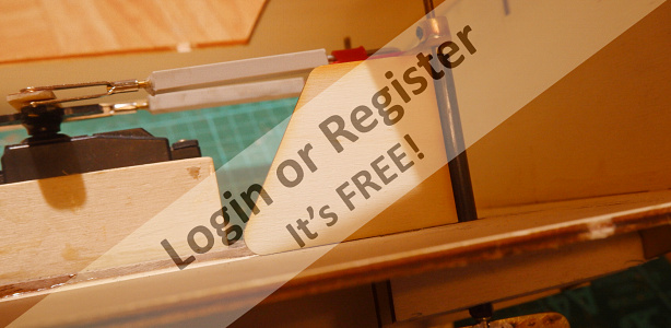
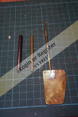
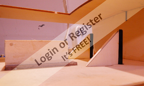
The rudders and the tubes I have made from stock, it is a bit like a scrapheap challenge, all were made from materials I had accumulated over the years. The whole thing is rather composite with the outer tube from 6mm o/d carbon fibre tube into which was placed an inner liner of brass tubing, another length of brass tubing which fitted snugly inside this was cut into three bearing lengths of 10mm, to be place at top centre and bottom of the rudder shaft which fitted snugly inside this tubing and will be fixed at the final points with Ca. The rudder blades were made from thin brass sheet epoxied together to give a suitable thickness and then slotted and soldered to the rudder shaft. All this fits together like a Russian Doll. When fitted the spaces between the centre bearing and the top and bottom bearings will be filled with Vaseline for waterproofing and smooth running. (Service intervals will be 500 hours!) The protruding part of the Carbon Fibre tube inside the hull can be supported by an upright. Note the one shown is a cut-out from the cabin windows and proves ideal for this, also they are an exact right-angle and can be used as a square in spots where other squares cannot reach!
Having done all this a dry fit in the hull with the servo and the linkages was completed and I am pleased to say I have a smooth and positive rudder action. The linkages were made from servo control wire with an adjustable quick link at the servo end and a fixed wire at the rudder end held in place with a swingkeeper. (Slec) The main arm of the linkage was from 4mm sq plastic.
Sorry if this wordage is a bit complicated but I hope the pics will make all clear.
Next Time – Fitting the Prop shafts.
Geoff.
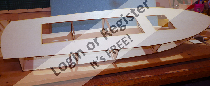
Since last time I have removed the deck from the board with formers attached and turned it over and fitted the upper deck, a straightforward task. As the formers have curved tops it is essential to make sure that the deck is glued to them across the whole width so that the deck takes on the same curvature, making sure that the deck meets and is securely glued to the outer points of the formers, also make sure that the deck is fitted centrally on the formers, this can be checked along the formers to ensure that it is placed centrally. I also marked the centre of the deck to ensure that it fitted centrally at the last former. I had pinned the centre of the deck to the bow former so that it stayed put while the rest of the deck was lined up. I must say that the accuracy of the parts of this model and the way they fit together does help in keeping the builders work accurate and furthermore it seems to demand accuracy from the builder, acting as a mentor in its own way.
With the hull now upside down on the deck, I have started to use a slab of plastic foam under the hull, firstly to give it a bit of stability on account of the curved deck and also to protect the deck from bruising by chippings or anything else that may be on the bench.
The lower formers were now glued in place, simply done and it was time to think about how the twin rudders would work to my own arrangement. I have devised my own way of building the rudder and linkage assembly because I have the time to do this, but the components mentioned in the handbook will be adequate and work well, so if you are pushed for time with an impatient son or grandson waiting by your elbow, then use the commercial components.
As I mentioned in the last entry, I have planned to use a Futaba standard servo mounted in an upright position and working a push pull action on the rudders with their arms facing inwards. A test run had proved that this should work.
So, it was now a question of mounting the rudder tubes and rudders into the hull. In the kit, a former is placed in the lower side of the hull either side of the hole where the rudder is to be fixed. The holes are already cut in the lower deck and the outer hull skin so again all lines up easily. These formers were used, and I made up a softwood spacer with a 6mm hole drilled vertically to line up with the hole in the deck and put the formers in place and glued with the spacer in between.
The rudders and the tubes I have made from stock, it is a bit like a scrapheap challenge, all were made from materials I had accumulated over the years. The whole thing is rather composite with the outer tube from 6mm o/d carbon fibre tube into which was placed an inner liner of brass tubing, another length of brass tubing which fitted snugly inside this was cut into three bearing lengths of 10mm, to be place at top centre and bottom of the rudder shaft which fitted snugly inside this tubing and will be fixed at the final points with Ca. The rudder blades were made from thin brass sheet epoxied together to give a suitable thickness and then slotted and soldered to the rudder shaft. All this fits together like a Russian Doll. When fitted the spaces between the centre bearing and the top and bottom bearings will be filled with Vaseline for waterproofing and smooth running. (Service intervals will be 500 hours!) The protruding part of the Carbon Fibre tube inside the hull can be supported by an upright. Note the one shown is a cut-out from the cabin windows and proves ideal for this, also they are an exact right-angle and can be used as a square in spots where other squares cannot reach!
Having done all this a dry fit in the hull with the servo and the linkages was completed and I am pleased to say I have a smooth and positive rudder action. The linkages were made from servo control wire with an adjustable quick link at the servo end and a fixed wire at the rudder end held in place with a swingkeeper. (Slec) The main arm of the linkage was from 4mm sq plastic.
Sorry if this wordage is a bit complicated but I hope the pics will make all clear.
Next Time – Fitting the Prop shafts.
Geoff.
▲
⟩⟩
nasraf
Colin H
jbkiwi
mturpin013
Martin555
RNinMunich
Seanympth
Skydive130
|
💬 Re: HAKITS- PILOT LAUNCH-LARGER VERSION.
3 years ago by 🇬🇧 Seanympth (
Chief Petty Officer 2nd Class)✧ 87 Views · 2 Likes
Flag
Dear Geoff,
As ever brilliantly written and a clear guide, thank you Best wishes👍 ▲
⟩⟩
Martin555
mistyoptic
|
|
Login To
Remove Ads 💬 Re: HAKITS- PILOT LAUNCH-LARGER VERSION.
3 years ago by 🇬🇧 Martin555 (
Fleet Admiral)✧ 84 Views · 1 Like
Flag
Nice work Big Joe.
Martin555. ▲
⟩⟩
Seanympth
|
|
💬 Re: HAKITS- PILOT LAUNCH-LARGER VERSION.
3 years ago by 🇬🇧 mistyoptic (
Midshipman)✧ 88 Views · 1 Like
Flag
Super, Hope mine comes out as well as that., thanks for posting
Geoff. ▲
⟩⟩
Martin555
|
|
💬 Re: HAKITS- PILOT LAUNCH-LARGER VERSION.
3 years ago by 🇬🇧 BigJoe (
 Recruit) Recruit)✧ 86 Views · 5 Likes
Flag
Heres mine newly finished. Not tried yet !!!
▲
⟩⟩
Colin H
Seanympth
Martin555
Rookysailor
mistyoptic
|
📝 HAKITS- PILOT LAUNCH-LARGER VERSION.
3 years ago by 🇬🇧 mistyoptic ( Midshipman)
Midshipman)✧ 87 Views · 6 Likes · 1 Comment
Flag
💬 Add Comment
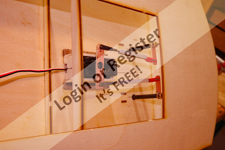
Fitting the Propshafts.
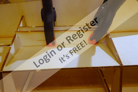
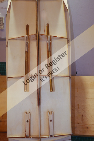
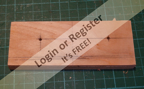
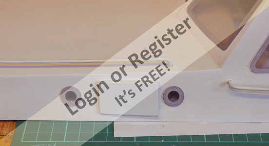
The model is designed for twin propshafts and motors and this option has been followed. The lower deck is already cut with a slot for the shaft as is one former and the outer bottom skin on either side. Like the rudder fixing, the shaft, will refer as singular although there are two, is held between two formers with spacers between. In the kit three spacers are provided which suit a 6mm shaft and the cut-outs in the hull formers and the slots in the deck are at this width . I had opted for the Caldercraft standard shafts, which at the length required come as 8mm diameter. To accommodate this wider diameter it was necessary to cut another spacer of 2mm to go alongside the three provided in the kit. This was no problem and again could be cut from waste from the laser cut sheets. These spacers as can be seen from the pic are shaped to give the correct angle to the propshaft, and to align with motors and hull exit hole. The four formers were now glued together to give an 8mm spacer and these were then glue between the propshaft inner and outer formers. A bottom and top spacer were created. The process I used was to glue the inner former and the lower spacer in place and then next day when this was set, took a round file, max diameter by coincidence, 8mm, and carefully followed the angle of the spacer to enlarge the hole in the former and the slot in the deck to take the larger shaft. The deck slot ends needed to be angled in line with the shaft angle. When all was a snug, but smooth fit, the top spacer and outer former were glued in place. When the glue had set sufficiently the shaft was withdrawn to be refitted in place later. The same process was followed on the other side, taking care to ensure that the propshafts at the motor end were at exactly the same height from the deck, a wooden jig was used to assist here. It will be important that the two shafts and motors are exactly aligned, although universal joints with be used as drive connectors, it is essential, with these smaller motors, that no energy is lost driving misaligned shafts.
The accompanying pics show the process and finished work. Note that in the pic showing the two propshafts in place, it is the camera that has bent them not me!!
▲
⟩⟩
nasraf
mturpin013
Seanympth
Skydive130
Colin H
Martin555
|
💬 Re: HAKITS- PILOT LAUNCH-LARGER VERSION.
3 years ago by 🇬🇧 Martin555 (
Fleet Admiral)✧ 82 Views · 0 Likes
Flag
Nice work Geoff.
This is always a tricky bit to do. That is the problem with cameras they do tend to distort closeup's. Martin555. ▲
⟩⟩
No likes yet
This member will receive 1 point for every like received |
📝 HAKITS- PILOT LAUNCH-LARGER VERSION.
3 years ago by 🇬🇧 mistyoptic ( Midshipman)
Midshipman)✧ 84 Views · 7 Likes · 1 Comment
Flag
💬 Add Comment
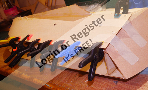
The Transom and Bottom skins.
Having made provision for the installation of the rudders and Propshafts it was time to move on to fixing the transom and bottom skins.
The transom is a broad piece of liteply which bends quite evenly to follow the curve in top deck and the two straight edges of the lower deck. I must say that I did go against the instructions in the kit here which say, fit the transom to the end of the lower deck and the underside of the upper deck. In dry fitting it was found to be difficult to get the transom to fit under the deck and at the same time follow the curve of the deck. There was no component on the underside of the deck to prevent the transom slipping further under the deck without then following the line of the deck. As there was adequate material to fit the transom on the outside edge of the upper deck. I did this and am happy with the result, in that the transom now has a good fit with the upper deck and the curve has been followed faithfully. I wonder if the handbook has misquoted this operation.
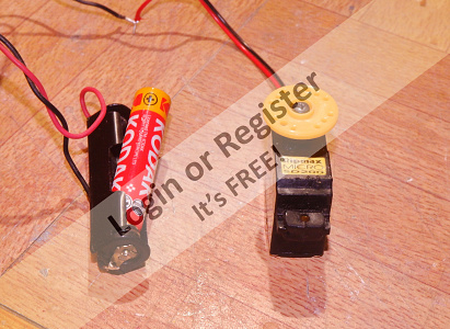
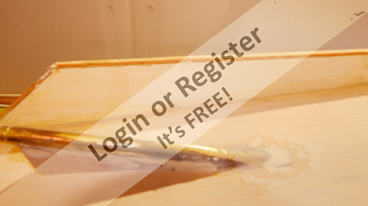
Having been left for a day it was time to sand of the surplus off the transom all round and then fit one of the lower skins to the hull. The accuracy of the shaping of the liteply skin needs little trimming and it was soon ready to attach to the hull. Using Gorilla Glue all mating surfaces were coated and the laying on began. The rudder tube outlet drilled in the skin gives a clear indication as to it's exact location. The attachment, to a large extent can be made by using spring clamps but I must say that a one point, I nearly lost an ear to a flying clamp which had catapulted itself from the model and crashed into the window. In the points where a bit more pressure is required and where clamps will not stay put, I used one small wood screw, which will later be withdrawn, and some wooden cocktail stick nails as used on my Morston kit. After three hours it all seems secure but will leave overnight to harden and then fix the other side another day. Since the last blog I have been experimenting with adapting an old servo to be a radar scanner driver. This was quite simple to do and just soldered two wires to the motor terminals and cut the stop lug off the output shaft. On trial with one alkaline AAA cell this was still going strong after 4 hours and is rotating at 15rpm. Perhaps a little faster than normal but near enough for jazz.
Having scanned the net for pictures of Pilot Launches I find that my nearest, the Port of Harwich has two good examples that I may follow.


Having made provision for the installation of the rudders and Propshafts it was time to move on to fixing the transom and bottom skins.
The transom is a broad piece of liteply which bends quite evenly to follow the curve in top deck and the two straight edges of the lower deck. I must say that I did go against the instructions in the kit here which say, fit the transom to the end of the lower deck and the underside of the upper deck. In dry fitting it was found to be difficult to get the transom to fit under the deck and at the same time follow the curve of the deck. There was no component on the underside of the deck to prevent the transom slipping further under the deck without then following the line of the deck. As there was adequate material to fit the transom on the outside edge of the upper deck. I did this and am happy with the result, in that the transom now has a good fit with the upper deck and the curve has been followed faithfully. I wonder if the handbook has misquoted this operation.
Having been left for a day it was time to sand of the surplus off the transom all round and then fit one of the lower skins to the hull. The accuracy of the shaping of the liteply skin needs little trimming and it was soon ready to attach to the hull. Using Gorilla Glue all mating surfaces were coated and the laying on began. The rudder tube outlet drilled in the skin gives a clear indication as to it's exact location. The attachment, to a large extent can be made by using spring clamps but I must say that a one point, I nearly lost an ear to a flying clamp which had catapulted itself from the model and crashed into the window. In the points where a bit more pressure is required and where clamps will not stay put, I used one small wood screw, which will later be withdrawn, and some wooden cocktail stick nails as used on my Morston kit. After three hours it all seems secure but will leave overnight to harden and then fix the other side another day. Since the last blog I have been experimenting with adapting an old servo to be a radar scanner driver. This was quite simple to do and just soldered two wires to the motor terminals and cut the stop lug off the output shaft. On trial with one alkaline AAA cell this was still going strong after 4 hours and is rotating at 15rpm. Perhaps a little faster than normal but near enough for jazz.
Having scanned the net for pictures of Pilot Launches I find that my nearest, the Port of Harwich has two good examples that I may follow.

▲
⟩⟩
Colin H
nasraf
mturpin013
Martin555
jbkiwi
Seanympth
Skydive130
|
💬 Re: HAKITS- PILOT LAUNCH-LARGER VERSION.
3 years ago by 🇬🇧 Seanympth (
Chief Petty Officer 2nd Class)✧ 84 Views · 1 Like
Flag
Beautiful work, thank you for sharing, your 'screw' solution is brilliant as it means a good solid fix where clamps cannot work. Thank you for your inspiration
▲
⟩⟩
Martin555
|
📝 HAKITS- PILOT LAUNCH-LARGER VERSION.
3 years ago by 🇬🇧 mistyoptic ( Midshipman)
Midshipman)✧ 79 Views · 7 Likes · 1 Comment
Flag
💬 Add Comment
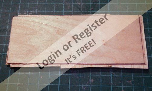
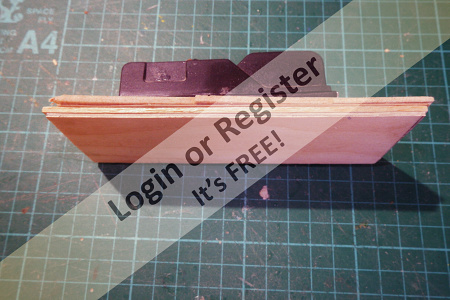
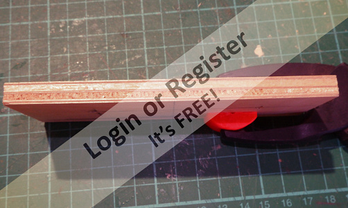
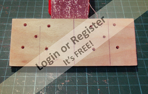
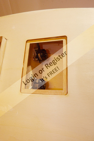
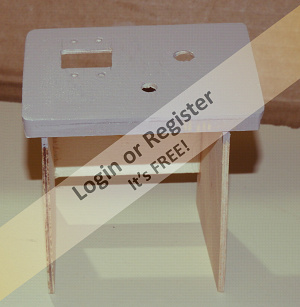
THE MOTOR PLATE AND INSTALLATION OF MOTORS.
The power units will be two small brushless motors, (Overlander) rated at 140 watts each. The plan is to fit them to a single motor plate made from mainly ply but some balsa. During the years that I flew electric model aircraft I found that Liteply, although as the name suggests, is light but has very little strength when used to hold motors or servos, especially where it has to be drilled for screws. I developed a way of laminating thinner ply with balsa and when glued, clamped in a press to dry and harden. The result is a lamination much stiffer and stronger than a plywood of the same thickness. In fact, a piece of 6mm balsa between a sandwich of 2mm ply may as well be bricks and mortar!
Using this technique, I prepared the laminations for assembly to give the plate. The build up was, 2mm ply plate, 2mm balsa plate, grain long ways, .8mm ply plate, 2mm balsa plate, grain vertical and finally the other outer edge 2mm ply. These laminations were glued with gorilla wood glue and then clamped firmly between to bits of board in the wooden jaws of my wood working vice. In the morning I released a plate which could almost have been steel! If I were selling this product, I would say that the balsa laminations dampen vibration and sound, but it may be only fancy!
By mounting the two motors on the one plate it is essential that complete accuracy is required if the motors are to run true to the propshafts, also the motor plate must be at a complimentary angle to the propshafts and the motor drives exactly spaced to the centre of the prop shafts.
The drive shafts exit the deck at an angle of 18deg. and I scratched for a long time with protractors and the number of degrees etc, I did not resort to log tables or sines and cosines but by simply doing a dry fit I found that the angle was the same, 18deg, this was because the plate was angled to the vertical and the shafts to the horizontal. Life became less stressful again. The plate was marked with the projection of the propshafts at the point where the plate would be. To ensure accuracy of the motor mounting in the plate a 3 mm hole was drilled at the point marked, this is the diameter of the motor shaft and then with the spindle through this hole, the star fixing plate was clamped in place, with the motor attached and the four mounting holes drilled for the 3mm screws being used. When this had been done the motor was removed and the centre hole enlarged to 20mm to give airway to the motor. I had made up wooden brackets which straddled the former where the plate was to be mounted and these slotted so that the plate would be the correct distance from the end of the propshaft. When all had been dry tested the plate was epoxied in place. I would like to claim a complete success, but one of the motors had to have a very fine shim inserted at the top just to line up comfortably with the shaft. Other wise the job is done. The rudder tubes were also inserted at this point so that the side skins can be fixed as the next job.
Geoff
▲
⟩⟩
Martin555
Colin H
jbkiwi
nasraf
mturpin013
Skydive130
Ianh
|
💬 Re: HAKITS- PILOT LAUNCH-LARGER VERSION.
3 years ago by 🇳🇿 jbkiwi (
Fleet Admiral)✧ 71 Views · 2 Likes
Flag
Nice motor fitting job👍
JB ▲
⟩⟩
Martin555
mistyoptic
|
📝 HA KITS PILOT LAUNCH Larger Version.
3 years ago by 🇬🇧 mistyoptic ( Midshipman)
Midshipman)✧ 73 Views · 7 Likes · 1 Comment
Flag
💬 Add Comment
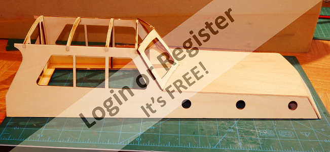
SIDESKINS AND CABIN.
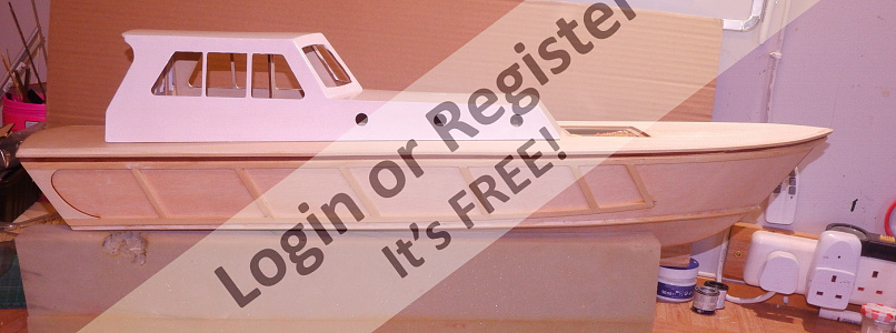
After the demanding, (for me) fitting of the two motors and aligning with propshafts it was now time to add the sideskins to the hull. This is a fairly straightforward hull to skin and the design ensures that the shape is maintained through the formers and the lower skins already being in place. It is one of those tasks that demands more than two hands, clamps and taping to get the skin into place all round so that the glue adheres to the ply skin along the whole length top and bottom. Pulling the ply into the bow again resorted to using small woodscrews as a temporary hold, to be withdrawn and holes filled when the glue has set overnight. As an enhancement to the kit, I flattened the ply join at the bow and fixed a mahogany stem piece to give a sharp stem and to cover the ends of the ply grain. I do not like end grain of plywood to be exposed under the waterline and so have fixed a capping strip along the length of the keel to cover the grain here.
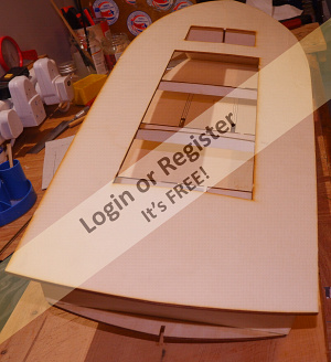
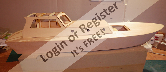
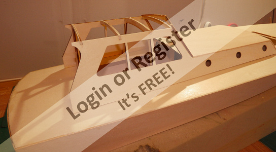
With the hull well on the way, the next stage was to build the cabin, which is built on a base which surrounds raised edges to the ‘hold’. Formers are slotted into the base frame and then the cabin sides glued to the formers. The cabin can now be removed from the deck and the building continued on the flat surface of the bench. This is a good feature to the design which enables work on the cabin and final touches to the hull to be carried on. The forward roof of the cabin is fixed and then the front window frames, when the glue has dried on this, the top cabin rook can be fixed. The roof has a curvature, so clamping was necessary, and easily executed by using the tops of the window apertures as a fixing point. The cabin will be a removable feature to allow access to the hold for attention to speed controllers, and batteries. This is a generous area and should present no problem in getting these components into place.
It is my plan to run both controllers through a Y lead from the Rx motor channel, both esc to have +ve disconnected and the receiver run from a separate 4.8v Rx pack. This battery will also power the cooling fan near to the motors. The Hydra 30amp controllers have an on off switch and each will have its own supply from a 7.2v Nimh 2000mah. There will be a control centre for the two esc switches, the fan switch and the Rx switch. Batteries will be connected directly to its esc. Having run this set up on the bench all seems to work fine with a neutral point which stops both motors.
Next stage is to start thinking about what features I will install on the deck and superstructure and I am aiming to run a rubber buffer around the deck as in the picture.

After the demanding, (for me) fitting of the two motors and aligning with propshafts it was now time to add the sideskins to the hull. This is a fairly straightforward hull to skin and the design ensures that the shape is maintained through the formers and the lower skins already being in place. It is one of those tasks that demands more than two hands, clamps and taping to get the skin into place all round so that the glue adheres to the ply skin along the whole length top and bottom. Pulling the ply into the bow again resorted to using small woodscrews as a temporary hold, to be withdrawn and holes filled when the glue has set overnight. As an enhancement to the kit, I flattened the ply join at the bow and fixed a mahogany stem piece to give a sharp stem and to cover the ends of the ply grain. I do not like end grain of plywood to be exposed under the waterline and so have fixed a capping strip along the length of the keel to cover the grain here.
With the hull well on the way, the next stage was to build the cabin, which is built on a base which surrounds raised edges to the ‘hold’. Formers are slotted into the base frame and then the cabin sides glued to the formers. The cabin can now be removed from the deck and the building continued on the flat surface of the bench. This is a good feature to the design which enables work on the cabin and final touches to the hull to be carried on. The forward roof of the cabin is fixed and then the front window frames, when the glue has dried on this, the top cabin rook can be fixed. The roof has a curvature, so clamping was necessary, and easily executed by using the tops of the window apertures as a fixing point. The cabin will be a removable feature to allow access to the hold for attention to speed controllers, and batteries. This is a generous area and should present no problem in getting these components into place.
It is my plan to run both controllers through a Y lead from the Rx motor channel, both esc to have +ve disconnected and the receiver run from a separate 4.8v Rx pack. This battery will also power the cooling fan near to the motors. The Hydra 30amp controllers have an on off switch and each will have its own supply from a 7.2v Nimh 2000mah. There will be a control centre for the two esc switches, the fan switch and the Rx switch. Batteries will be connected directly to its esc. Having run this set up on the bench all seems to work fine with a neutral point which stops both motors.
Next stage is to start thinking about what features I will install on the deck and superstructure and I am aiming to run a rubber buffer around the deck as in the picture.

▲
⟩⟩
Martin555
Colin H
jbkiwi
nasraf
mturpin013
Ianh
Seanympth
|
💬 Re: HA KITS PILOT LAUNCH Larger Version.
3 years ago by 🇬🇧 Seanympth (
Chief Petty Officer 2nd Class)✧ 76 Views · 1 Like
Flag
Well done, that's very quick work. Its looking beautiful
▲
⟩⟩
Martin555
|
📝 HAKITS- PILOT LAUNCH-LARGER VERSION.
3 years ago by 🇬🇧 mistyoptic ( Midshipman)
Midshipman)✧ 68 Views · 7 Likes · 1 Comment
Flag
💬 Add Comment
Completing the Hull structure and Sundry.
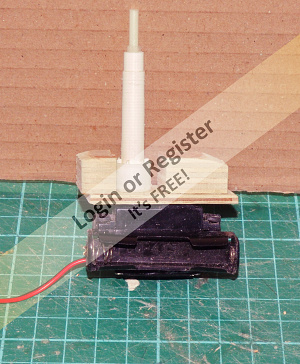
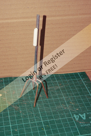
It has been one of those periods where building a model seems to not be making much progress despite spending the usual amount of time on it and then suddenly another major step has been completed. I have been working on finishing the hull, which has involved trimming and sanding the side skins to blend into the deck and to have a good appearance where the skins come together at the chine line. The ‘slot’ for the rubber surround to the deck has been created by setting a strip of lime round the hull at a 6mm distance under the deck rubbing strip, to get a fairly equal gap all round a 6mm mahogany strip was stuck under the chine before adding the lower strip, again some surplus material from a previous kit. This was fairly successful but a bit tricky around the curvature at the bow. The inner edges of the two strips were chamfered using a 6mm diamond burr in a minidrill. When the hull has been painted then I will affix the rubber tubing with a contact adhesive. It is in fact screenwasher tubing from the motor trade. I have made a bit more progress with the radar scanner and this is ready to fit on the underside of the rear cabin roof. A single AAA battery holder had been glued to the side of the servo and the whole is now ready to fix. The outer tube of the upstand and the inner tube has been salvaged from a liquid soap dispenser, Yet to be made is the scanner itself. Progress has been made on the aerial array supports constructed from brass rod and tube into which the aluminium mast will sit, removable for transport. The St. Cuthbert has a mesh guard grid across the stern, I do not know its exact purpose and I have been working on fabricating this as well. On the hull sides the rubbing strips have been fixed and gaps filled and sanded ready to start the finishing. Due to a bit of impatience on my part I have done some painting on the cabin.


It has been one of those periods where building a model seems to not be making much progress despite spending the usual amount of time on it and then suddenly another major step has been completed. I have been working on finishing the hull, which has involved trimming and sanding the side skins to blend into the deck and to have a good appearance where the skins come together at the chine line. The ‘slot’ for the rubber surround to the deck has been created by setting a strip of lime round the hull at a 6mm distance under the deck rubbing strip, to get a fairly equal gap all round a 6mm mahogany strip was stuck under the chine before adding the lower strip, again some surplus material from a previous kit. This was fairly successful but a bit tricky around the curvature at the bow. The inner edges of the two strips were chamfered using a 6mm diamond burr in a minidrill. When the hull has been painted then I will affix the rubber tubing with a contact adhesive. It is in fact screenwasher tubing from the motor trade. I have made a bit more progress with the radar scanner and this is ready to fit on the underside of the rear cabin roof. A single AAA battery holder had been glued to the side of the servo and the whole is now ready to fix. The outer tube of the upstand and the inner tube has been salvaged from a liquid soap dispenser, Yet to be made is the scanner itself. Progress has been made on the aerial array supports constructed from brass rod and tube into which the aluminium mast will sit, removable for transport. The St. Cuthbert has a mesh guard grid across the stern, I do not know its exact purpose and I have been working on fabricating this as well. On the hull sides the rubbing strips have been fixed and gaps filled and sanded ready to start the finishing. Due to a bit of impatience on my part I have done some painting on the cabin.
▲
⟩⟩
Martin555
Colin H
RNinMunich
robbob
Ianh
jbkiwi
Seanympth
|
💬 Re: HAKITS- PILOT LAUNCH-LARGER VERSION.
3 years ago by 🇳🇿 jbkiwi (
Fleet Admiral)✧ 71 Views · 1 Like
Flag
Progressing nicely👍
JB ▲
⟩⟩
Martin555
|
📝 HAKITS- PILOT LAUNCH-LARGER VERSION.
3 years ago by 🇬🇧 mistyoptic ( Midshipman)
Midshipman)✧ 67 Views · 8 Likes · 4 Comments
Flag
💬 Add Comment
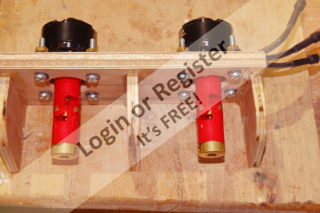
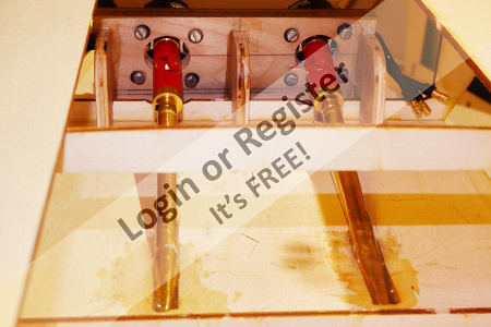
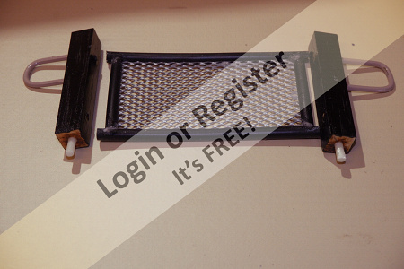
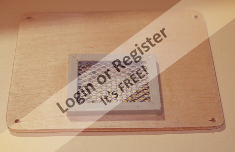
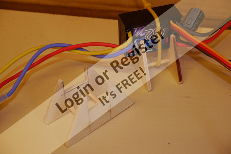
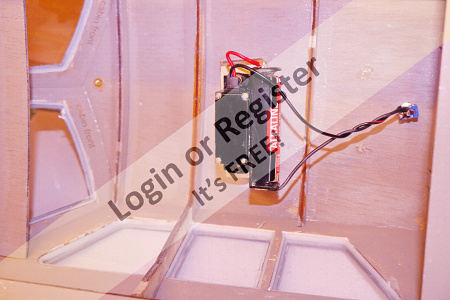
Lots of Bits and Pieces
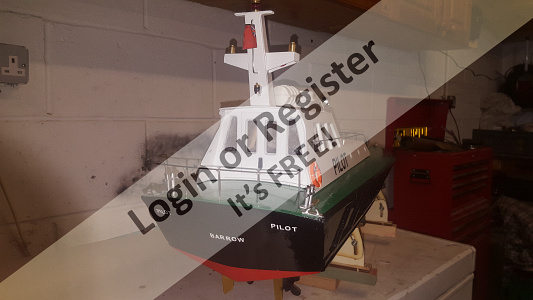
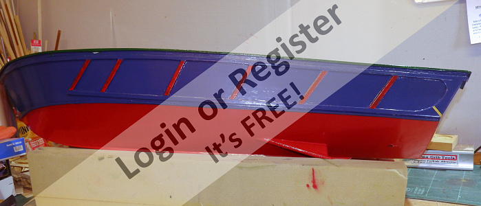
Although have not reported of late, I have been busy working on the Pilot Launch. Mainly on the many components which will go toward the finished boat. The pics will show the various items. A control panel which will be mounted between the propshafts and will house, between the uprights the 1800ma 4AA battery pack in a square shape which will power the ventilating fan above the motors, and the receiver. The panel will have mounted on it a switch for the fan, a switch for each esc and a switch, three way, which will switch on the receiver in one direction and connect a charging lead for the other. The pack can then be charged in situ. On the last blog I admitted that I did not know the purpose of the grid that is mounted at the stern of the vessel behind the cabin, today I rang the Harwich Haven engineers and they informed me that it is a recovery platform that folds out to the horizontal and is then lowered into the water to retrieve a person, presumably a pilot that missed his footing! The grid has been salvaged from an old pencil pot and the surround tubing from an outer sleeve of a control snake, gently slitted from end to end and pushed over the side of the mesh. Painting yet to be finished. I have used a similar piece of this mesh to cover and opening in the forward hatch under which will be a small electric fan. The exhaust will be taken from a slot on each side of the cabin covered by a louvre. I realise that in real life that the placement of this air inlet would be unrealistic and, in some conditions, would not take long for the North Sea to fill the boat with water, but I am not expecting too many giant waves breaking over the bow on Woodbridge Model Boat Pond! Two holders have been constructed to hold the ESCs in position and these will be epoxied to the lower deck and the devices held in place by a cable tie. The holders have been designed to give all round ventilation. Finally, a picture of the hull in the process of painting, a job I least relish in this hobby.
All for now, except that I will be allowed out to play next week so may be able to get the Morston in the water, if there are not too many families at the pond, do like a bit of peace and quiet for the maiden voyage.
Geoff
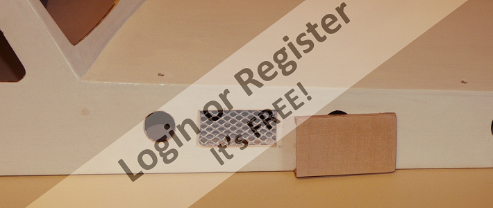
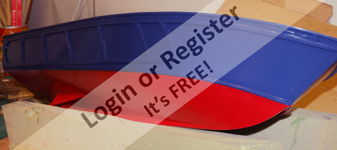
▲
⟩⟩
Martin555
Ianh
jbkiwi
Skydive130
Colin H
mturpin013
RNinMunich
Graham93
|
💬 Re: HAKITS- PILOT LAUNCH-LARGER VERSION.
3 years ago by 🇬🇧 Martin555 (
Fleet Admiral)✧ 45 Views · 0 Likes
Flag
Thank you Geoff,
It is good to be back. Martin555. ▲
⟩⟩
No likes yet
This member will receive 1 point for every like received |
|
Login To
Remove Ads 💬 Re: HAKITS- PILOT LAUNCH-LARGER VERSION.
3 years ago by 🇬🇧 mistyoptic (
Midshipman)✧ 47 Views · 1 Like
Flag
Thank you for your encouragement Martin and will look to improve the layout on the next instalment. I must say that I write this out in Word and then copy and paste and so it does come out a bit cramped on the blog page. So glad you are back with us, have missed you.
Best wishes Geoff. ▲
⟩⟩
Martin555
|
|
💬 Re: HAKITS- PILOT LAUNCH-LARGER VERSION.
3 years ago by 🇬🇧 Martin555 (
Fleet Admiral)✧ 45 Views · 2 Likes
Flag
Hi Geoff,
You are doing a great job. I like how she is coming together. Looking good. Just one little request could you please break up the text a bit with more spaces and paragraphs as i found i keep reading the same piece several times. It might be just me and my glasses. I used to follow my finger but it keeps leaving smudges on the screen LOL!!! Martin555. ▲
⟩⟩
mistyoptic
RNinMunich
|
|
💬 Re: HAKITS- PILOT LAUNCH-LARGER VERSION.
3 years ago by 🇩🇪 RNinMunich (
Fleet Admiral)✧ 67 Views · 2 Likes
Flag
Coming along well👍
Novel ESC holders Geoff, vaguely Egyptian 😉 Wishing you happy playing next week 🤞 Cheers, Doug 😎 ▲
⟩⟩
Martin555
mistyoptic
|
📝 HAKITS- PILOT LAUNCH-LARGER VERSION.
3 years ago by 🇬🇧 mistyoptic ( Midshipman)
Midshipman)✧ 60 Views · 6 Likes · 2 Comments
Flag
💬 Add Comment
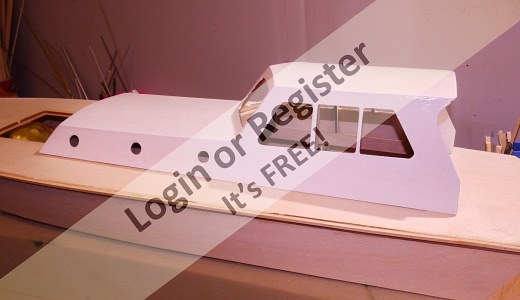
Cabin.
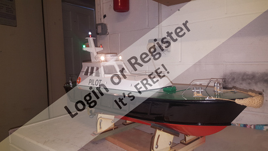
The cabin has now been finished and has the antenna masts fitted and the working radar. (See Vid) The louvres over the fan exhausts are fitted to the outside of the lower cabins. In preparation for the fitting of the rubber buffer around the edge of the deck I have inserted some 1/8 brass rod into the rubber and have shaped it to fold around the point at the end of the deck to the transom. This should take some of the stress off the adhesive when it is stuck into place. A similar joining piece will be in place at the join at the bow. Painting of the hull is still progressing. Soon will be able to get the radio get into place as the next job. Geoff.
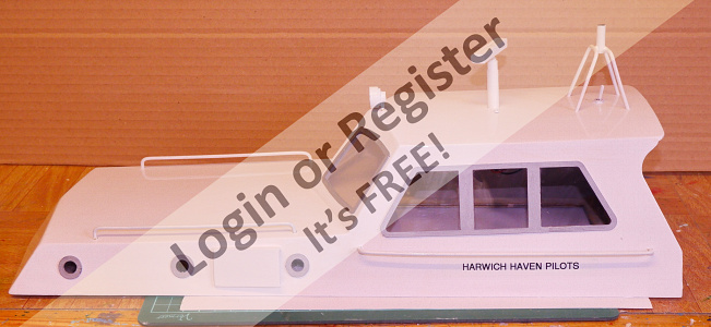
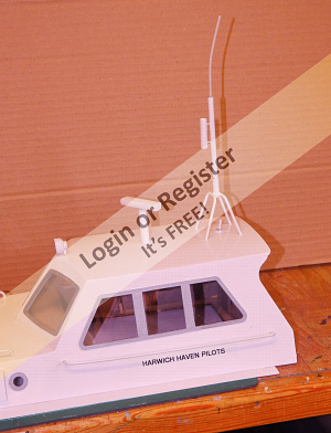
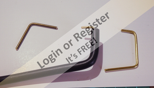
The cabin has now been finished and has the antenna masts fitted and the working radar. (See Vid) The louvres over the fan exhausts are fitted to the outside of the lower cabins. In preparation for the fitting of the rubber buffer around the edge of the deck I have inserted some 1/8 brass rod into the rubber and have shaped it to fold around the point at the end of the deck to the transom. This should take some of the stress off the adhesive when it is stuck into place. A similar joining piece will be in place at the join at the bow. Painting of the hull is still progressing. Soon will be able to get the radio get into place as the next job. Geoff.
▲
⟩⟩
Colin H
Martin555
stevedownunder
RNinMunich
jbkiwi
mturpin013
|
💬 Re: HAKITS- PILOT LAUNCH-LARGER VERSION.
3 years ago by 🇬🇧 Seanympth (
Chief Petty Officer 2nd Class)✧ 64 Views · 2 Likes
Flag
Hi Geoff,
Happy Easter, that is beautiful work, well done ▲
⟩⟩
Martin555
mistyoptic
|
|
💬 Re: HAKITS- PILOT LAUNCH-LARGER VERSION.
3 years ago by 🇬🇧 mturpin013 (
 Admiral) Admiral)✧ 62 Views · 2 Likes
Flag
Hi Geoff, that's a nice job you've made of the cabin, it looks great
▲
⟩⟩
Martin555
mistyoptic
|


Login To
Remove Ads
Remove Ads