Join Us On Social Media!

|

|

|
Download The App!
Login To
Remove Ads
Remove Ads
Login To
Remove Ads
Remove Ads
Model Boats Website
E.F.S. Surveyor
7 Posts · 11 Followers · 43 Photos · 66 Likes
Began 1 year ago by
 Canada
Follow This Thread
Not currently following
> Click to follow
> Click to follow
Latest Post 7 months ago by
| Most recent posts shown first (Show Oldest First) | (Print Booklet) |
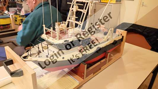
📝 Last Run of 2023
7 months ago by 🇨🇦 Westwind ( Chief Petty Officer 1st Class)
Chief Petty Officer 1st Class)✧ 64 Views · 21 Likes · 10 Comments
Flag
💬 Add Comment
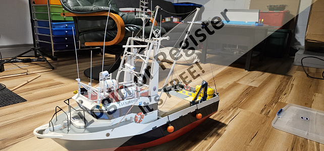
A cold and gloomy Dec day, perfect for my completed Surveyor. This is surly my last run of 2023.


▲
⟩⟩
jumpugly
MartinW
RossM
River Rat
Len1
robbertderouw
EdW
Wolle
Fred
stevedownunder
DWBrinkman
RNinMunich
GaryLC
Mike Stoney
Ronald
boatmam
hermank
RodC
Doogle
LewZ
Colin H
|
💬 Re: Last Run of 2023
7 months ago by 🇨🇦 Westwind (
Chief Petty Officer 1st Class)✧ 43 Views · 0 Likes
Flag
Hi Robbert, the yellow barrles on the back are 3d printed
▲
⟩⟩
No likes yet
This member will receive 1 point for every like received |
|
Login To
Remove Ads 💬 Re: Last Run of 2023
7 months ago by 🇳🇱 robbertderouw (
 Able Seaman) Able Seaman)✧ 38 Views · 0 Likes
Flag
What did you use as those yellow bouys on the aft deck?
▲
⟩⟩
No likes yet
This member will receive 1 point for every like received |
|
💬 Re: Last Run of 2023
7 months ago by 🇬🇧 Mike W (
 Leading Seaman) Leading Seaman)✧ 45 Views · 0 Likes
Flag
Looks the part on the water. It has been incredibly gloomy over the past couple of days though so we all need some lights on!
Calm waters for 2024 and new projects. Happy New Year! ▲
⟩⟩
No likes yet
This member will receive 1 point for every like received |
|
💬 Re: Last Run of 2023
7 months ago by 🇩🇪 RNinMunich (
 Fleet Admiral) Fleet Admiral)✧ 50 Views · 0 Likes
Flag
Good idea Westwind👍
Very similar to the way I hid the switches, at the base of the froward funnel, on my H class destroyer. On the original probably an equipment locker or rope/cable storage. But actually I meant the larger 'box' structure with the yellow rim, highly reminiscent of my set of food storage boxes😉 Altogether a very impressive model , a Proper Job👍 Cheers, Doug😎 ▲
⟩⟩
No likes yet
This member will receive 1 point for every like received |
|
💬 Re: Last Run of 2023
7 months ago by 🇨🇦 Westwind (
Chief Petty Officer 1st Class)✧ 54 Views · 1 Like
Flag
Hi RN, I put my on/off switch in the 'lunch box', I not sure what would be in it on the 1:1 ship.
▲
⟩⟩
RNinMunich
|
|
💬 Re: Last Run of 2023
7 months ago by 🇩🇪 RNinMunich (
Fleet Admiral)✧ 59 Views · 2 Likes
Flag
Ahoy there! It's them thar blasted Minions again.
Absconded from the Orca I'll be bound🙄 Excellent build WW, compliments👍👍👍 Just one question: What's in the lunch box on deck??😁😋 Cheers, Doug😎 
▲
⟩⟩
GaryLC
hermank
|
|
💬 Re: Last Run of 2023
7 months ago by 🇬🇧 GaryLC (
 Captain) Captain)✧ 82 Views · 3 Likes
Flag
Looks very realistic on the water, and really nice sharp photos on a dull day that shows off the lights and fine detail. A great end result and a nice-looking boat.
▲
⟩⟩
hermank
RNinMunich
AlessandroSPQR
|
|
💬 Re: Last Run of 2023
7 months ago by 🇨🇦 RodC (
 Lieutenant) Lieutenant)✧ 58 Views · 4 Likes
Flag
Looks wonderful on the water. I adore your lights...& at least with it being a dull day we can actually see them in operation. You just ignited my excitement for the new year's sailing season.
So...you arent going to run tomorrow?? Our last sail here in Toronto was mid-Nov, 16th i believe was our #32 at Bluffers Park for 2023. Happy New Year to all. ▲
⟩⟩
AlessandroSPQR
Mike Stoney
Westwind
hermank
|
|
💬 Re: Last Run of 2023
7 months ago by 🇬🇧 Doogle (
 Commodore) Commodore)✧ 65 Views · 3 Likes
Flag
As posted earlier, she's very realistic on the water. A great build 👍👍
▲
⟩⟩
Ronald
Westwind
AlessandroSPQR
|
|
💬 Re: Last Run of 2023
7 months ago by 🇬🇧 Colin H (
Fleet Admiral)✧ 69 Views · 3 Likes
Flag
Now that looks so good on the water it could have been a full sized boat. Great model shipmate. Cheers Colin.
▲
⟩⟩
RNinMunich
Westwind
AlessandroSPQR
|
Login To
Remove Ads
Remove Ads
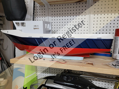
📝 May to Dec
7 months ago by 🇨🇦 Westwind ( Chief Petty Officer 1st Class)
Chief Petty Officer 1st Class)✧ 74 Views · 11 Likes · 3 Comments
Flag
💬 Add Comment
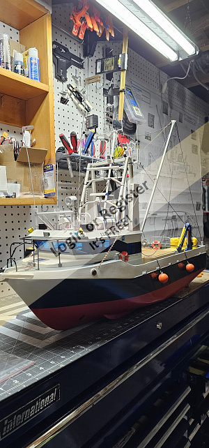
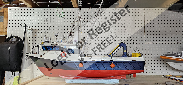
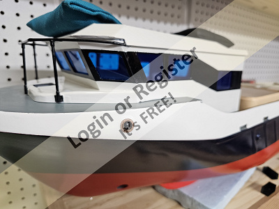
I started my build in May and have just completed the ship, so about 7 months for this build. My ship includes dual ESCs, bow thruster, always on nav lights, switched deck lights, switched radars, switched spot light, spot light rotates left and right, fishing booms can be manually set out over the sides. I thinking of trying to deploy an underwater camera from the booms.
I had to manufacture several parts due to low quality of the supplied bits, and I added extra rigging to keep the booms stable when running. Last thing to do is rebalts the ship now that all the parts are on.
I found while running the ship earlier this year the ship sails very nicely, has a high water line and is very stable.
So now it's time to clean the shop up, get a few repairs completed on other models then get ready for the next kit.
▲
⟩⟩
RodC
Mike Stoney
Albert90
robbertderouw
Len1
AlessandroSPQR
River Rat
Colin H
Wolle
Scratchbuilder
Ronald
|
💬 Re: May to Dec
7 months ago by 🇳🇱 robbertderouw (
Able Seaman)✧ 62 Views · 2 Likes
Flag
Nice boat, I purchased a build one recently and added electronics to switch all the lights.
Sailed it first time last evening and it performs well. 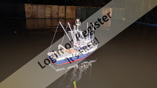
▲
⟩⟩
EdW
Westwind
|
|
Login To
Remove Ads 💬 Re: May to Dec
7 months ago by 🇬🇧 craigG (
Able Seaman)✧ 69 Views · 1 Like
Flag
Really like your workshop bud
▲
⟩⟩
Westwind
|
|
💬 Re: May to Dec
7 months ago by 🇨🇦 Ronald (
 Admiral) Admiral)✧ 78 Views · 2 Likes
Flag
Very well done! Congratulations on a great build.
▲
⟩⟩
AlessandroSPQR
Westwind
|
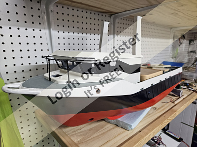
📝 A small update
11 months ago by 🇨🇦 Westwind ( Chief Petty Officer 1st Class)
Chief Petty Officer 1st Class)✧ 82 Views · 7 Likes
Flag
💬 Add Comment
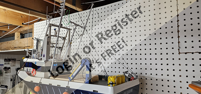
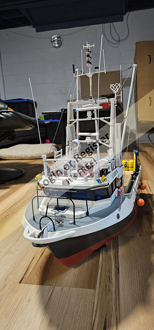
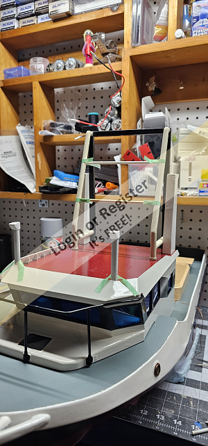
in the past couple weeks I have added most of the equipment to the roof and completed most of the mast. Next I plan to install the working radars and search light

▲
⟩⟩
Mike Stoney
Colin H
boatmam
Chum444
jbkiwi
Scratchbuilder
Ronald
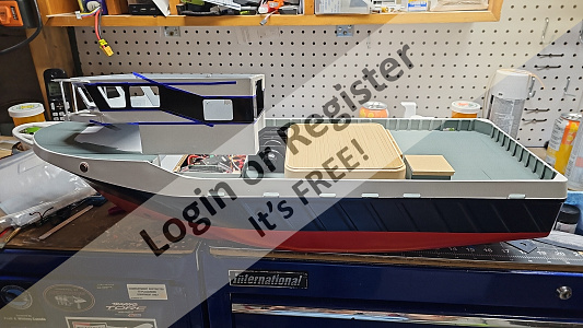
📝 a little update
1 year ago by 🇨🇦 Westwind ( Chief Petty Officer 1st Class)
Chief Petty Officer 1st Class)✧ 85 Views · 7 Likes
Flag
💬 Add Comment
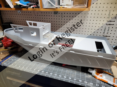
Back with another short update, I've been able to get most of the paint done and complete much of the hull and deck equipment. I also set about building up and painting the cabin, cargo hatch, and winch. I'm currently in the process of building the stacks, light tower and antenna platform. I struggled a bit with the inaccurate part sizes used by this kit but eventually manged to make it work. I also had several of the cast parts brake on me while sanding them the material used is very brittle, I've had to manufacture several parts as the kit parts fail, I also plan on replacing some of the soft metal parts especially the prop guards as they will bend if you look at them sideways.
I was able to get it in the water as my local club had a showing a few weeks ago, and I can report no leaks and a very well behaved boat.
That being said I'm happy with the look of the kit so far and I'm sure I'll have a great model in the end.
I was able to get it in the water as my local club had a showing a few weeks ago, and I can report no leaks and a very well behaved boat.
That being said I'm happy with the look of the kit so far and I'm sure I'll have a great model in the end.
▲
⟩⟩
Colin H
boatmam
Scratchbuilder
Ronald
RNinMunich
cdnfurball
MouldBuilder
📝 Week 3, 4 and 5
1 year ago by 🇨🇦 Westwind ( Chief Petty Officer 1st Class)
Chief Petty Officer 1st Class)✧ 90 Views · 4 Likes
Flag
💬 Add Comment
Progress has been slow but steady lately due to real world work so...
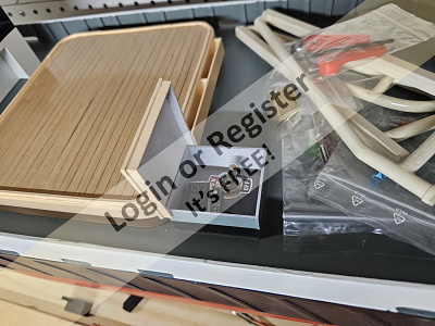
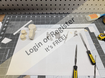
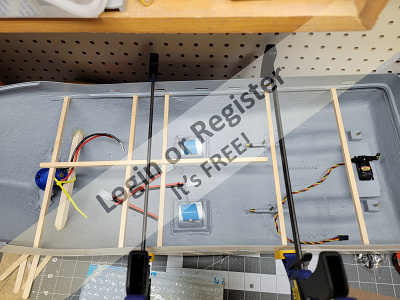
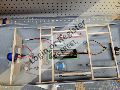
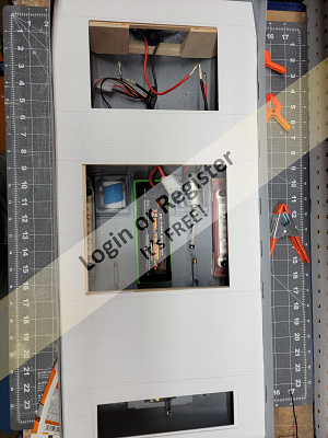
After test fitting the deck and lots of sanding and trimming I add a few more deck support beams where I thought they were needed. I also found that the deck ended up being about a mm lower then the freeing ports. I added scrap strips of plastic to the support beams leaving several gaps allowing for mounting ti-wraps and most of my wiring, as Bob Ross might say happy little accent.
Next fuse panel and bilge pump installed, ESCs and battery telemetry mounted, wiring secured. Time to install the deck, then the forward bulkhead, I used Guerrilla Glue Construction glue to mount attach the deck and once dry automotive body filler to fill and gaps and create a uniform fit to the side walls. Next was to install the forward deck using the same methods.
The instruction in the next section are described as detailing the deck. In this plastic strips are to be added horizontally and vertically to the side walls. My kit did not include the plastic strips and I wonder if they are not included as the detailing seams to be optional, but I was able to source wood strips that look about right, so more cutting, gluing and sanding. Once happy with these I fit the support walls for the cabin and hold access door. Next the exciting task of pouring a few cups off water on to the deck to see if shes water tight, I happy to say she was comply dry.
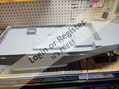
Time to fit the two non functioning storage lockers under the extensions of the upper deck. None of these pieces fit correctly as described in the instruction and some had odd angles as if left over from another kit design. After lots of trial fitting and trimming I managed to get something that resembled the intent of the instructions.
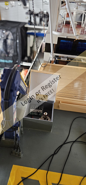
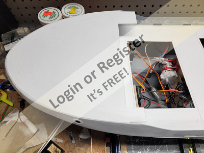
Last thing to build was the access box for the on/off switch, then finally it was time to paint. After taping off all the access holes I applied a few layers of primer and once dry a few layers of white paint before the sun went down, and its back to work for me. The rest of the paint will have to wait for now.
As I write this I realize I forgot to wire and instill the on/off switch so once the paint is finished I'll have to rework some wiring.
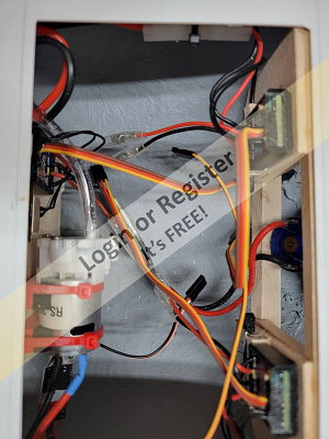

After test fitting the deck and lots of sanding and trimming I add a few more deck support beams where I thought they were needed. I also found that the deck ended up being about a mm lower then the freeing ports. I added scrap strips of plastic to the support beams leaving several gaps allowing for mounting ti-wraps and most of my wiring, as Bob Ross might say happy little accent.
Next fuse panel and bilge pump installed, ESCs and battery telemetry mounted, wiring secured. Time to install the deck, then the forward bulkhead, I used Guerrilla Glue Construction glue to mount attach the deck and once dry automotive body filler to fill and gaps and create a uniform fit to the side walls. Next was to install the forward deck using the same methods.
The instruction in the next section are described as detailing the deck. In this plastic strips are to be added horizontally and vertically to the side walls. My kit did not include the plastic strips and I wonder if they are not included as the detailing seams to be optional, but I was able to source wood strips that look about right, so more cutting, gluing and sanding. Once happy with these I fit the support walls for the cabin and hold access door. Next the exciting task of pouring a few cups off water on to the deck to see if shes water tight, I happy to say she was comply dry.
Time to fit the two non functioning storage lockers under the extensions of the upper deck. None of these pieces fit correctly as described in the instruction and some had odd angles as if left over from another kit design. After lots of trial fitting and trimming I managed to get something that resembled the intent of the instructions.
Last thing to build was the access box for the on/off switch, then finally it was time to paint. After taping off all the access holes I applied a few layers of primer and once dry a few layers of white paint before the sun went down, and its back to work for me. The rest of the paint will have to wait for now.
As I write this I realize I forgot to wire and instill the on/off switch so once the paint is finished I'll have to rework some wiring.
▲
⟩⟩
EdW
Colin H
RNinMunich
MouldBuilder
📝 Week 2
1 year ago by 🇨🇦 Westwind ( Chief Petty Officer 1st Class)
Chief Petty Officer 1st Class)✧ 98 Views · 6 Likes · 2 Comments
Flag
💬 Add Comment
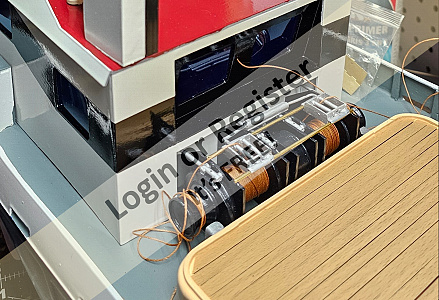
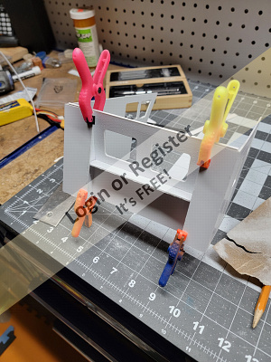
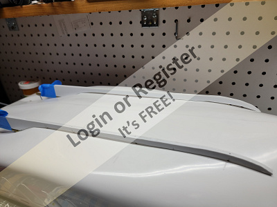
While waiting for the rains to stop so I could start painting, I decided to do a bit of work on the cabin, with I little effort and reference back to the assembly CD pictures, I was able to build up as much as the cabin as possible without the decks installed. Next I did some work on the trawl winch and after hours of sanding I did manage to assemble the core parts, but as I'm not thrilled with the way it looks so far I might order a winch kit and use it instead.
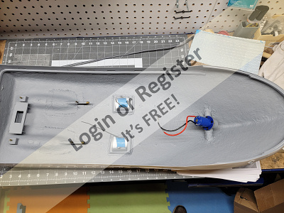
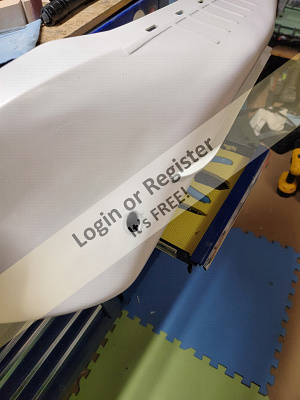
Finally the rain cleared and I set about preparing the hull for paint when I noticed I had forgot to install the rudder servo mount so I got out a servo and trimmed the mount for a nice snug fit. I noticed the mount was a bit wobble so I reinforced it with some scarp bits and got to painting. Two coats of automotive spray primer did the trick.
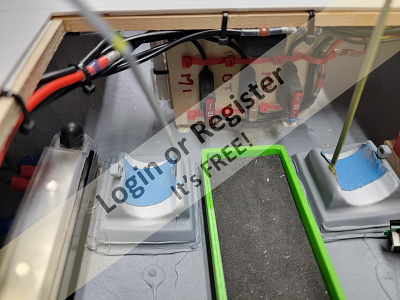
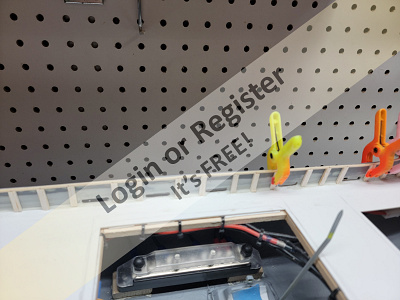
With paint dried it time to lay out the deck supports and internal components, two motors, bow thruster, a home built water detector, battery tray and a negative and positive bus bar. I'm also going to add a remotely controlled bilge pump but still waiting on the pump to arrive. First I had to trim about 7mm from each side of the deck to get it to fit in the hull, then mark the position of the openings and cut and lay out the support beams I added some bulkheads to mount the ESCs and pump, and an extra beam under the bow thruster for support, I had a 3d printed battery try that worked well and attached wooden strips to keep it above any water that might get in.
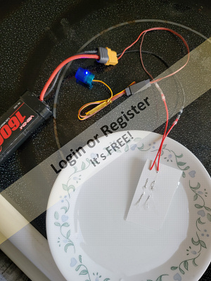
Next I had to build and test the water detector, two wires with several centimetres of exposed wire threaded through a piece of plastic and separated about a cementer apart with a rotating LED lamp worked wheel and I found that the more the wires got wet the brighter the LED got.
Last thing I did this week was to test fit the deck and cabin. Will have to see how much I get done next week.
Finally the rain cleared and I set about preparing the hull for paint when I noticed I had forgot to install the rudder servo mount so I got out a servo and trimmed the mount for a nice snug fit. I noticed the mount was a bit wobble so I reinforced it with some scarp bits and got to painting. Two coats of automotive spray primer did the trick.
With paint dried it time to lay out the deck supports and internal components, two motors, bow thruster, a home built water detector, battery tray and a negative and positive bus bar. I'm also going to add a remotely controlled bilge pump but still waiting on the pump to arrive. First I had to trim about 7mm from each side of the deck to get it to fit in the hull, then mark the position of the openings and cut and lay out the support beams I added some bulkheads to mount the ESCs and pump, and an extra beam under the bow thruster for support, I had a 3d printed battery try that worked well and attached wooden strips to keep it above any water that might get in.
Next I had to build and test the water detector, two wires with several centimetres of exposed wire threaded through a piece of plastic and separated about a cementer apart with a rotating LED lamp worked wheel and I found that the more the wires got wet the brighter the LED got.
Last thing I did this week was to test fit the deck and cabin. Will have to see how much I get done next week.
▲
⟩⟩
Colin H
RNinMunich
chugalone100
Len1
flaxbybuck
hermank
|
💬 Re: Week 2
1 year ago by 🇨🇦 Westwind (
Chief Petty Officer 1st Class)✧ 95 Views · 1 Like
Flag
Yes the 3 ESCs and other equipment will be upfront under the cabin. I'm thinking of placing the RX in the cabin as high off the water as I can get it
▲
⟩⟩
RNinMunich
|
|
💬 Re: Week 2
1 year ago by 🇬🇧 flaxbybuck (
Captain)✧ 95 Views · 0 Likes
Flag
I'm liking the look of it so far. I guess the ESC and receiver will be mounted in the forward compartment ?😉
▲
⟩⟩
No likes yet
This member will receive 1 point for every like received |
📝 E.F.S. Surveyor
1 year ago by 🇨🇦 Westwind ( Chief Petty Officer 1st Class)
Chief Petty Officer 1st Class)✧ 118 Views · 10 Likes · 1 Comment
Flag
💬 Add Comment
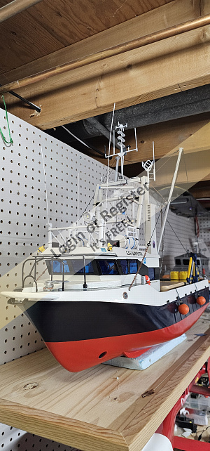
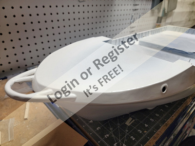
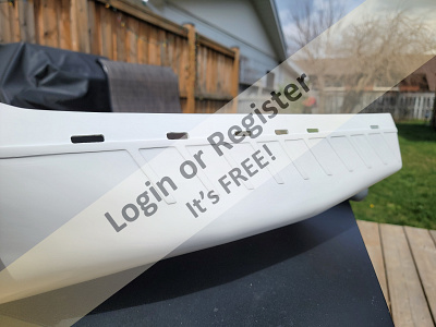
After sitting on the shelf for about a year I decided to start my build of the E.F.S. Surveyor kit by Deans Marine. She is a 1/20 scale representation of a fisheries research vessel, measuring 780mm in length with a beam of 250mm, she's wide and should be pretty stable on the water.
First step was to trim the hull and apply a layer of Bondo putty to smooth out the fibreglass that will be above the deck. Next the twin stuffing tubes needed to be carefully aligned and again Bondo, the a layer of fibreglass on top for added strength. Once all that was satisfactory I cut out the freeing ports, then installed the deck supports and motor mounts. Then it was time to install the rudder shafts and I ran into my fist problem, the brass tubes for the rudders supplied were the wrong size, about .04” to big, fortunately I had some scrap tube that was a perfect snug fit. With a bit of grease I should be able to keep the water out, next I noted that the kit did not include a way to support the tubes but did indicate I could solder a scale a brass to the tube and epoxy it to the hull. I elected to cut up blocks of wood to insert the tubes through and epoxy them in place, before carefully drilling my holes for the tubes. After this was completed I installed the two skegs adding an extra sheet of plastic to make them each three sheets about 5mm wide and again used Bondo to take up the gapes created by a badly designed cutouts. Last I installed the bow thruster and bondo and sanded it all smooth. After a quick leak check in the tub I will fibreglass the hull along ware the skeg pins are located and cove the interior part of the bow thruster in marine sealant. That is it for this week, cheers


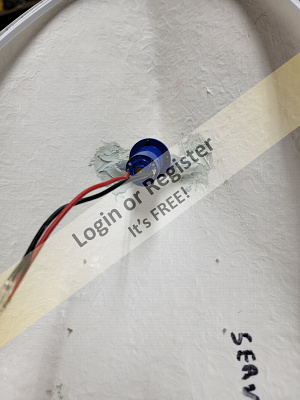

First step was to trim the hull and apply a layer of Bondo putty to smooth out the fibreglass that will be above the deck. Next the twin stuffing tubes needed to be carefully aligned and again Bondo, the a layer of fibreglass on top for added strength. Once all that was satisfactory I cut out the freeing ports, then installed the deck supports and motor mounts. Then it was time to install the rudder shafts and I ran into my fist problem, the brass tubes for the rudders supplied were the wrong size, about .04” to big, fortunately I had some scrap tube that was a perfect snug fit. With a bit of grease I should be able to keep the water out, next I noted that the kit did not include a way to support the tubes but did indicate I could solder a scale a brass to the tube and epoxy it to the hull. I elected to cut up blocks of wood to insert the tubes through and epoxy them in place, before carefully drilling my holes for the tubes. After this was completed I installed the two skegs adding an extra sheet of plastic to make them each three sheets about 5mm wide and again used Bondo to take up the gapes created by a badly designed cutouts. Last I installed the bow thruster and bondo and sanded it all smooth. After a quick leak check in the tub I will fibreglass the hull along ware the skeg pins are located and cove the interior part of the bow thruster in marine sealant. That is it for this week, cheers
▲
⟩⟩
Colin H
RNinMunich
chugalone100
MouldBuilder
johnf
Mike Stoney
pressonreguardless
flaxbybuck
hermank
cdnfurball
|
💬 Re: E.F.S. Surveyor
1 year ago by 🇬🇧 flaxbybuck (
Captain)✧ 108 Views · 0 Likes
Flag
This looks like it will be an interesting build and I will be watching to see how you get on. Please keep taking photos of the build - it really helps us to appreciate the work you are doing.😊😉
▲
⟩⟩
No likes yet
This member will receive 1 point for every like received |


Login To
Remove Ads
Remove Ads