
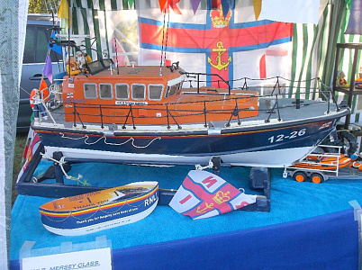
Mersey Class Lifeboat 1/12th Scale

By Gregg 93 entries 10 Feb 2012 — 3 Dec 2016
16Likes
85Comments
Chapter 22 / 93

93 chapters · Page 3 of 10

Gregg #22 of 93 1

HULL PAINTING

Now that all the necessary holes through the hull have been done and made sure they are in the correct places, its time to start painting the hull. I prefer to now remove the earlier "test fitted" items, props, rudders etc and get the main coat of paint on.
This mersey version has a white band to the lower hull, classifying it as a carriage launched version. red hull varieties means its normally kept at anchor [in water], as this is the antI fouling paint, to reduce/slow down the marine life from attaching to the smooth lines.
I used "Halfords - Appliance White" for this, applying several light/dust coats to start with, allowing each dust coat to flash off first, before the next.
Once sufficient paint coats has been applied and the primer is fully covere, its time to leave the hull alone to air dry for a few hours, before removing the masking and then leaving the hull for 3 days for ALL the thinners in the paint to evaporate.
failure to leave this type of paint for a few days to dry off will cause you greif later, as if you repaint over this paint now, you run the risk of it "crazing" or "forming micro bubbles" 12 months down the line. Then you have no choice but to flat it ALL down and start again.
Gregg #23 of 93 1

Second hull colour

Now that the lower hull colour has had sufficient time to dry fully [3 days], its time now to remask the hull and put on the deep blue. I first use some tamiya masking/lining tape to mark the "split", then use ordinary masking tape to attach the paper covering.
I then applied a few dust coats of "ford galaxy Blue", which Ive been told is the nearest to the actual RNLI blue used. Once the dust coats had dried sufficiently, I applied a couple of good coats of paint and again, left in a warm room for an hour, before switching the heater off and allowing to cool overnight.
Gregg #24 of 93 1

Hull detail.

After removing the last lot of masking , after painting the blue coat on, the hull was left for 2 days to dry off. I then added the red/yellow lining tape and the main hull decals, depth markings etc. I prefer to attach these whilst the paint is still "soft", as they bond better. The hull will be getting a couple of coats of clear laquer, but not untill all work on the hull is complete.
Reason......... if you scratch/damage the paint, its much easier to repaint the "base colours" or do a quick "touch in", but once it is coated with laquer, its a bigger problem to do a "touchin", so I prefer to save the final laquer coat till much later.
Gregg #25 of 93 1

hull decals pt2

the remaining hull decals have now been applied and the twin 900 size motors fitted inside. They had their alloy mounts glass fibre bonded to the hull floor/ I drilled some extra holes in th bases to allow the fibre resin to "flow through" for better bonding. the motors were fitted with a couple of blts to the mounts and attached to the prop shafts with their couplings, so to ensure correct alignment as the motor mounts bonded to the hull.
Gregg #26 of 93 1

window cutting

Whilst the hull paintwork is drying out, its time to start on the upper cabin moulding. The windows are already marked out by "indentation", but strongly recommend you try a window panel against these detents first before you mark Or cut anything out. I say this from past experience as some marking can be a little oversize. Undersize you can cope with by either a bit of file work or sawing. Once you have checked the window apertures, clearly mark them out first. I then prefer to drill a series of small holes around the inside of my "mark" line, then simply "join the dots", all that is then needed is a careful bit of filing /sanding to get the hole on to the actual line, remember to recheck with a window panel at intervals, just to make sure.
Incidentally, you will notice some thick black tape on the deck of my cabin, this was to prevent the drill chuck from damaging the delicate glass fibre as I was drilling the pilot holes. Spinning drill chucks and glass or plastic dont mix !
Gregg #27 of 93 1

windows pt2

I have now completed cutting and drilling out the cabin windows. I have also marked each window [on a paper template] with the actual window numbers which accurately "fit" each window aperture, as some of the windows supplied, were slightly different sizes, so watch out for this, dont simply cut a window to one size, not unless you are making your own glazing panels of course, but I used a "branded" supplier who can supply "laser cut perspex windows and frames.
Gregg #28 of 93 1

flying bridge

Now that the windws have been cut out and their edges sanded to rid it of nasty sharp glass fibres [be warned!]. I first bonded some plastic strips to the end edges of the glass fibre cabin with some stabilit express, as it will be from these that the rear cabin components will plasticweld to. Otherwise it means every time you want to attach something to the cabin, you have to bond each item on individually, so get it all done in one go.
then after careful study of both plans and actual photographs, I made some cuts to the rear cabin to get the outlines right, then made up the basic "shell" components to shape the flying bridge.
Start with the floor and the steering position, then the side boxes, as these are flat and square and the rest follows easily afterwards.
Gregg #29 of 93 1

flying bridge pt2

A lttle bit more "boxing in" has been done now on the flying bridge, adding the floor, side boxes and throttle pedestal.
Gregg #30 of 93 1

cabin door

This was made up as a 3 layer sandwich, to keep it simple and robust, plus saves trying to cut from 4mm plasticard! The inner and outer layers are white plasticard an d the one was used as a template for the other. the inner piece was cut from clear perspex to act as the window bit.a further outer ring was made for the outer window frame.
Gregg #31 of 93 1

door pt2

The window outer frame was first painted, so as not to mark the clear window section, once assembled, then bonded on once dry.
I then drilled a series of holes around the frame support and glued in some short lengths of plastic rod, to simulate the fixing bolts. Please remember that although genuine scale bolts [in brass for example] look really great for details, brass weights substantially more than plastic and weight does have to be considered when building a larger scale boat, if you still want it to be able to move on the water without then having to go to the extremes of twin brushless motors and 24volts !

Delete this post?

It will be removed from the site.

Discard this draft?

Your draft will be deleted and cannot be recovered.

You have an unfinished draft

What would you like to do with it?