Join Us On Social Media!

|

|

|
Download The App!
Login To
Remove Ads
Remove Ads
Login To
Remove Ads
Remove Ads
Model Boats Website
HMCS Snowberry 1/72 conversion to HMS Buttercup, K193
10 Posts · 9 Followers · 131 Photos · 72 Likes
Began 3 years ago by
 United Kingdom
Follow This Thread
Not currently following
> Click to follow
> Click to follow
Latest Post 2 years ago by
| Oldest posts shown first (Show Newest First) | (Print Booklet) |
📝 HMCS Snowberry 1/72 conversion to HMS Buttercup, K193
3 years ago by 🇬🇧 Scratchbuilder ( Vice Admiral)
Vice Admiral)✧ 149 Views · 7 Likes · 9 Comments
Flag
💬 Add Comment
Ladies and Gents.
I have always been an ardent fan of the Flower Class Corvettes.In fact I can’t get enough of them.
To that end I over the years have built I think, four of them in various conversions and styles.
My first build was the Matchbox 1/72 plastic kit HMS Bluebell built over 30 years ago with my two then very young sons.Bluebell remains in Stirling service to this day and a short story of her can be seen in my boat harbour.
Some twenty years ago I bought the Matchbox replacement to HMS Bluebell.This of course is the Revell HMCS Snowberry.If I remember back then it cost me the sum of £25.99….bargain.
It has lain in its box over the years remaining it the plastic protective bags.
The only incursion into the bags was to steal the rudder to replace the one on HMS Bluebell which I broke with a bad sailing manoeuvre one day (more on its replacement in due course).
Nothing personal against HMCS Snowberry I scratched my head to think what with reasonable ease I could convert the kit into.
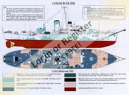
After long and careful consideration I decided to convert her into HMS Buttercup K193 during build.
Just a little different in so much that although based on the Anti Submarine Corvette she was converted into a Fleet Minesweeper variant.Fitted with a Mark V cable drum aft and the conspicuous acoustic hammer on the bow.
This I hope will make an interesting project.
Like most I have built quite a bit during lockdown but this is as we come out from the dark side.
I will start posting pictures soon as I have a reasonable amount of the basic Hull and propulsion done so will be posting retrospectively.Once I get to the current point in build I will photograph as I go.
Hope you enjoy.
Regards Bill👍


I have always been an ardent fan of the Flower Class Corvettes.In fact I can’t get enough of them.
To that end I over the years have built I think, four of them in various conversions and styles.
My first build was the Matchbox 1/72 plastic kit HMS Bluebell built over 30 years ago with my two then very young sons.Bluebell remains in Stirling service to this day and a short story of her can be seen in my boat harbour.
Some twenty years ago I bought the Matchbox replacement to HMS Bluebell.This of course is the Revell HMCS Snowberry.If I remember back then it cost me the sum of £25.99….bargain.
It has lain in its box over the years remaining it the plastic protective bags.
The only incursion into the bags was to steal the rudder to replace the one on HMS Bluebell which I broke with a bad sailing manoeuvre one day (more on its replacement in due course).
Nothing personal against HMCS Snowberry I scratched my head to think what with reasonable ease I could convert the kit into.
After long and careful consideration I decided to convert her into HMS Buttercup K193 during build.
Just a little different in so much that although based on the Anti Submarine Corvette she was converted into a Fleet Minesweeper variant.Fitted with a Mark V cable drum aft and the conspicuous acoustic hammer on the bow.
This I hope will make an interesting project.
Like most I have built quite a bit during lockdown but this is as we come out from the dark side.
I will start posting pictures soon as I have a reasonable amount of the basic Hull and propulsion done so will be posting retrospectively.Once I get to the current point in build I will photograph as I go.
Hope you enjoy.
Regards Bill👍
▲
⟩⟩
stevedownunder
jbkiwi
redpmg
Commodore-H
Martin555
MouldBuilder
Colin H
|
💬 Re: HMCS Snowberry 1/72 conversion to HMS Buttercup, K193
3 years ago by 🇬🇧 Scratchbuilder (
Vice Admiral)✧ 147 Views · 1 Like
Flag
Martin.
Many thanks. Yes,that’s the plan. These great little ships rarely had refits and the toll of the Atlantic weather was always evident. Will start more on the blog later. Regards Bill. ▲
⟩⟩
Martin555
|
|
Login To
Remove Ads 💬 Re: HMCS Snowberry 1/72 conversion to HMS Buttercup, K193
3 years ago by 🇬🇧 Martin555 (
 Fleet Admiral) Fleet Admiral)✧ 149 Views · 0 Likes
Flag
Bill,
In the photos I really like the weathering on this Corvette. Do you plan on weathering this one too ? Martin555. ▲
⟩⟩
No likes yet
This member will receive 1 point for every like received |
|
💬 Re: HMCS Snowberry 1/72 conversion to HMS Buttercup, K193
3 years ago by 🇬🇧 Scratchbuilder (
Vice Admiral)✧ 148 Views · 3 Likes
Flag
Hi Andy.
Many thanks for your thoughts and your certainly not teaching Granny….I am always keen to learn and always grateful.Never to old to learn👍. Re the turret.I did similar on my first Corvette,but certainly didn’t think about the elevation idea🤔👍.I will have a look at that. Re your lighting ideas…all sounds good and thank you. I bought a Graupner ARTR 1/48 Corvette some time ago in need of care and attention and did the lighting on that one (some pictures attached sorry for poor quality and not really part of this blog) but have never tried on the 1/72 scale so your input is gratefully received. Will keep you posted on how it all goes. Regards Bill. 


▲
⟩⟩
stevedownunder
Martin555
MouldBuilder
|
|
💬 Re: HMCS Snowberry 1/72 conversion to HMS Buttercup, K193
3 years ago by 🇬🇧 Scratchbuilder (
Vice Admiral)✧ 148 Views · 3 Likes
Flag
Hi Red.
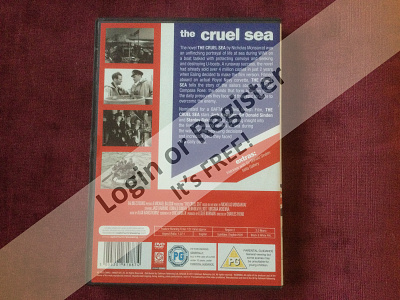
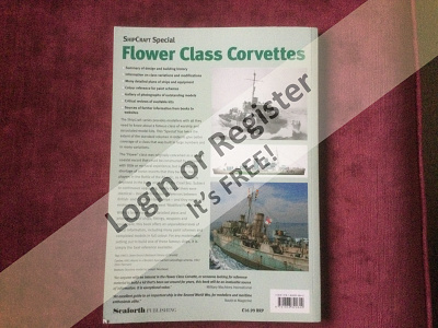
Your spot on re the rudder,and thank you. I have made a brass one from a larger one and will show it in the blog later.👍 Re Compass Rose…I have lost count of how many times I have seen the film.Just love it. I attach a couple of pictures of the DVD which if your interested you can get on Amazon for about £12.00. Also pictures of the Flower Class Corvette builders bible. More soon,and thanks again Regards Bill 

▲
⟩⟩
cormorant
stevedownunder
Martin555
|
|
💬 Re: HMCS Snowberry 1/72 conversion to HMS Buttercup, K193
3 years ago by 🇿🇦 redpmg (
 Commodore) Commodore)✧ 152 Views · 2 Likes
Flag
Good one Bill - the rudder should not be too hard to replace - you could always make a brass one which would probably be better if you are planning a working model - was glad to hear im not the only one who hoards kits for ever !!!!!!!!!!!!!
Currently thinking of tackling the 1/144th version - but it wont be built as Canadian - rather as the Compass Rose as I loved that film - watched it many times. hopefully might even be able to find some pictures of her on the web.......... A windfall might help with the purchase of the kit......... Have the book - still trying to find a copy of the CD - sad that none of Monseratt's later books lived up to his wartime stories with the possible exception of The Kapillan of Malta. ▲
⟩⟩
Scratchbuilder
Martin555
|
|
💬 Re: HMCS Snowberry 1/72 conversion to HMS Buttercup, K193
3 years ago by 🇬🇧 Spock66 (
 Chief Petty Officer 1st Class) Chief Petty Officer 1st Class)✧ 147 Views · 4 Likes
Flag
Hi Bill,
If teaching my Grannie... etc, please forgive. For the front gun rotation on my HMCS Regina, I used a spare channel on my Flysky (one of the rotary pots) to enable servo controlled left and right and by a paperclip cam, as it turned I had elevation and depression of same. For the Nav lights, I found 2mm LED's a perfect fit if drilled from rear of Nav housing before gluing to bridge and then fine wires through the bridge to a lighting board. I also had functioning searchlights, by using thin, but stiff copper wire (from old transformer, 'cos it was already enamel insulated) and ground the head off of each white LED (to make them flat but in scale), then put thin heatshrink around the wires to act as pillars so that they stood on the bridge and looked very much like searchlights on stalk mounts. The only other electrical extras I fitted were a dimmed down LED in wheelhouse and ('cos I'd drilled out the hatches) - flickering LED's in the engine room, together with a timed on and off controlled by a 555 chip - simple and cheap. Finally, by using plastic tube as conrod, I fitted a motor to underside of bridge that turned the Radar horn, controlled down by a miniature fixed pot to give about 10 revolutions per minute. If these ideas old hat, then sorry for that. If not might give some easy solutions to help achieve what you want. Cheers Andy ▲
⟩⟩
Scratchbuilder
Martin555
redpmg
Colin H
|
|
💬 Re: HMCS Snowberry 1/72 conversion to HMS Buttercup, K193
3 years ago by 🇬🇧 Martin555 (
Fleet Admiral)✧ 149 Views · 0 Likes
Flag
Excellent Bill.
Martin555. ▲
⟩⟩
No likes yet
This member will receive 1 point for every like received |
|
💬 Re: HMCS Snowberry 1/72 conversion to HMS Buttercup, K193
3 years ago by 🇬🇧 Scratchbuilder (
Vice Admiral)✧ 148 Views · 3 Likes
Flag
Hi Martin.
This boat is secretly being built for one of the Grandchildren in Edinburgh,the plan being that he won’t know anything about it until he sees it.His Dad helped build my first Corvette all those years ago. The beauty of these 1/72 scale boats is you have a lot of space to play with even for the small size. So far all the engine room and radio control components will be accessible and removable from the rear deck access opening so all the other decks are secured. I plan to have the front gun rotating,and am going to work on being able to raise and lower the acoustic hammer by servo. There will be I hope navigation and bridge lighting as well. Regards Bill ▲
⟩⟩
Colin H
Spock66
Martin555
|
|
💬 Re: HMCS Snowberry 1/72 conversion to HMS Buttercup, K193
3 years ago by 🇬🇧 Martin555 (
Fleet Admiral)✧ 149 Views · 1 Like
Flag
Hi Bill,
Glad to see you have this Build Log under way. Looking forward to the next update and very interested in seeing how you do all the modifications. Martin555. ▲
⟩⟩
Scratchbuilder
|
Login To
Remove Ads
Remove Ads
📝 So…. To the Build.
3 years ago by 🇬🇧 Scratchbuilder ( Vice Admiral)
Vice Admiral)✧ 146 Views · 8 Likes · 10 Comments
Flag
💬 Add Comment
Morning.
I previously made mention that I had started the construction of this Corvette before I started taking photographs with the intention of sharing a blog,so apologies if some of the pictures don’t show everything initially.
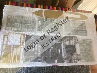
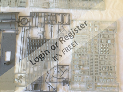
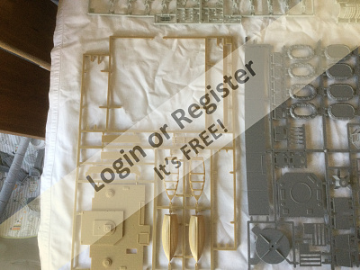
What’s in the Box.
Firstly note the different boxes.
Picture one shows the original Matchbox build,my first HMS Bluebell from over 30 years ago.
Picture two shows it’s replacement HMCS Snowberry probably bought over 20 years ago.
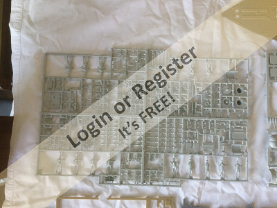
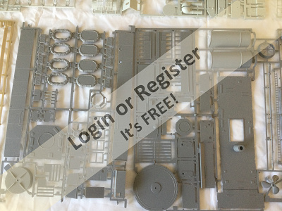
The remaining pictures show the contents which are all relatively the same as previously manufactured.
It’s interesting to note that on each sprig of parts the Made in England stamp has been erased after Matchbox were taken over I assume.
Please note that the main obvious missing section from these pictures is the hull.
This is because I constructed the basic hull prior to taking the pictures shown.
More on that later.
You will also note there are no instructions shown.Silly Billy lost them,or rather put them somewhere safe a long time ago and now because of many and increasing senior moments can’t find them!
Luckily I will be able to build from memory and referring to the other boats and pictures.
All being well I will be able to play catch up on the pictures soon.
The hull is in basic form is built and along with pictures will be the next post in a few days.
Hope everyone is well.Stay safe.
Regards Bill.


I previously made mention that I had started the construction of this Corvette before I started taking photographs with the intention of sharing a blog,so apologies if some of the pictures don’t show everything initially.
What’s in the Box.
Firstly note the different boxes.
Picture one shows the original Matchbox build,my first HMS Bluebell from over 30 years ago.
Picture two shows it’s replacement HMCS Snowberry probably bought over 20 years ago.
The remaining pictures show the contents which are all relatively the same as previously manufactured.
It’s interesting to note that on each sprig of parts the Made in England stamp has been erased after Matchbox were taken over I assume.
Please note that the main obvious missing section from these pictures is the hull.
This is because I constructed the basic hull prior to taking the pictures shown.
More on that later.
You will also note there are no instructions shown.Silly Billy lost them,or rather put them somewhere safe a long time ago and now because of many and increasing senior moments can’t find them!
Luckily I will be able to build from memory and referring to the other boats and pictures.
All being well I will be able to play catch up on the pictures soon.
The hull is in basic form is built and along with pictures will be the next post in a few days.
Hope everyone is well.Stay safe.
Regards Bill.
▲
⟩⟩
Rookysailor
stevedownunder
RNinMunich
Colin H
redpmg
Martin555
MouldBuilder
jbkiwi
|
💬 Re: So…. To the Build.
3 years ago by 🇬🇧 Scratchbuilder (
Vice Admiral)✧ 140 Views · 2 Likes
Flag
Morning chaps.
Just to thank those who have posted various links and updates on pictures and plans….and building instructions…very helpful.👍👍 Any info is always welcome. It pouring down here today in Sunny Devon,and she who must be obeyed is at work so I may sneak down to the boat shed later for a little relaxation and an update. Take care all. Regards Bill. ▲
⟩⟩
RNinMunich
Martin555
|
|
Login To
Remove Ads 💬 Re: So…. To the Build.
3 years ago by 🇺🇸 Cashrc (
Vice Admiral)✧ 140 Views · 2 Likes
Flag
I’ve thought about doing an RC conversion on this kit, well the Revell of Germany kit, for a while. I’ll be watching this, looks like fun and I’ll bet she’ll make a fine runner too.
▲
⟩⟩
Martin555
Scratchbuilder
|
|
💬 Re: So…. To the Build.
3 years ago by 🇬🇧 Rookysailor (
Commodore)✧ 151 Views · 3 Likes
Flag
Excellent photo's of the real ship, perfect for extra detailing and weathering.
Cheers Pete😊 ▲
⟩⟩
Martin555
Scratchbuilder
stevedownunder
|
|
💬 Re: So…. To the Build.
3 years ago by 🇬🇧 Martin555 (
Fleet Admiral)✧ 143 Views · 3 Likes
Flag
Hi Bill,
Here are a couple of links that i think would make interesting reading and may keep you out of mischief for a while. ▲
⟩⟩
stevedownunder
Rookysailor
Scratchbuilder
|


|
💬 Re: So…. To the Build.
3 years ago by 🇩🇪 RNinMunich (
Fleet Admiral)✧ 148 Views · 4 Likes
Flag
"You will also note there are no instructions shown.Silly Billy lost them,or rather put them somewhere safe a long time ago and now because of many and increasing senior moments can’t find them!"
Know the feeling Bill🤔 Had to grovel around the internet to find some instructions for my 1/350 Merit Ark Royal (1939). Had gone nuts tearing up the flat looking for them. These any good to you? See attached pdf. It's a slightly later version but the basics should be the same, just retooled I think. Your version, 05061, doesn't seem to be available on Revell's Download site. If not I can scan the instructions for my earlier version (05007) bought over 30 years ago here in Munich. First generation Revell version? I had just seen it advertised as NEW in ModellWerft (Model Shipyard), kinda German Model Boats, and thought she'd be a great partner for my 1/72 destroyer. I'll get to building her one day🙄 Cheers, Doug 😎 
▲
⟩⟩
Scratchbuilder
stevedownunder
Rookysailor
Martin555
|
|
💬 Re: So…. To the Build.
3 years ago by 🇬🇧 Scratchbuilder (
Vice Admiral)✧ 146 Views · 2 Likes
Flag
Hi Red.
I’m lucky, I have a good size boat shed for all my projects 👍. She who must be obeyed would not be amused if I was to build on the dining room table. The 1/72 kit is 34 1/4” long or 87 cms with a 5 1/2” or 14 cms beam. There is a lot of delicate parts,but if fitted correctly they can survive. I always use brass handrails for example which are at the extremities. Hope you enjoy the blog. Regards Bill. ▲
⟩⟩
Martin555
redpmg
|
|
💬 Re: So…. To the Build.
3 years ago by 🇿🇦 redpmg (
Commodore)✧ 147 Views · 3 Likes
Flag
Was quite put off the original Bill - we went to visit a friend - he was building one - seemed to take up the whole dining room table - ex would never have allowed that - probably the reason that only two of my boats are over 24in long - so never pursued it although the Matchbox kits were relatively cheap then. In current terms allowing for inflation the 1/144 version costs about double what the original did here at the time - thanks to our horrendous exchange rate.
Thinking about it the hull must only be about 3 1/2 ft - so not so terribly big - but it must be difficult to move without damaging anything. Looking at some of the parts in your pics begin to wonder if you would need a microscope to build the half size version........... Will be watching your blog with interest ▲
⟩⟩
Martin555
Scratchbuilder
Colin H
|
|
💬 Re: So…. To the Build.
3 years ago by 🇬🇧 Martin555 (
Fleet Admiral)✧ 146 Views · 1 Like
Flag
Hi Bill,
I will be following this with great interest as i too have an original Matchbox Corvette in the loft that one day i will get around to making (Hopefully) and it will be great to follow a corvette master. Martin555. ▲
⟩⟩
Scratchbuilder
|
|
💬 Re: So…. To the Build.
3 years ago by 🇭🇺 MouldBuilder (
Vice Admiral)✧ 144 Views · 2 Likes
Flag
By the way, who needs instructions.😁😁😂
▲
⟩⟩
Martin555
Scratchbuilder
|
|
💬 Re: So…. To the Build.
3 years ago by 🇭🇺 MouldBuilder (
Vice Admiral)✧ 144 Views · 2 Likes
Flag
Looking forward to this build Bill. I have the Trumpeter HMS Hood to start in the not too distant future. I will see what tips you can give as I have not made such an intricate model before. I am sure that my large hands and clumsy fingers will be against me all of the way.😁
▲
⟩⟩
Martin555
Scratchbuilder
|
📝 Hull build.Prop Shaft fitment.
3 years ago by 🇬🇧 Scratchbuilder ( Vice Admiral)
Vice Admiral)✧ 140 Views · 7 Likes · 3 Comments
Flag
💬 Add Comment
Good afternoon all.
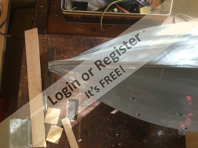
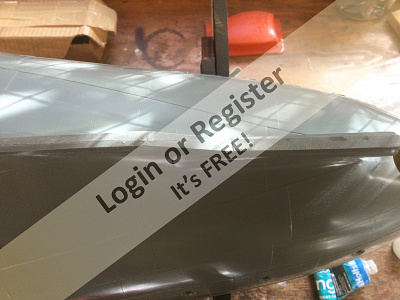
So here I will explain the build process re the above,ie Hull and prop shaft fitment.
Once again I apologise that a lot of this was done prior to taking pre blog pictures.
The Hull comes in four sections,two port and two starboard.(Sorry no pics of separate items)
Having cut them off the sprigs and filing away the rough edges then it is a simple task of joining them together.
I use Revell Contacta Professional glue as recommended but you could use any proprietary plastic glue.
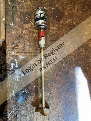
Having joined the relevant sides and allowing to set then I began to offer up the prop shaft prior to joining the port and starboard halves together.
The prop shaft came from Howes and is a 5” M4 Brass tube with Stainless steel shaft.
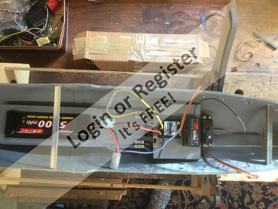
This length means that I can fit all my internal workings into the mid and aft sections of the hull apart from the battery.This makes everything accessible from the pre formed hole in the aft decking.
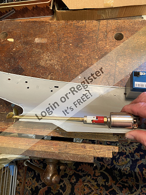
You will see in the pictures that I offer up the shaft and motor to the hull and as always I did many dry runs to check that the shaft and motor are as straight as possible.
This ensures less resistance,vibration/noise from the coupling and thus drain on battery.
Happy that all was aligned and square then I glued both hull halves together and left for 24 hours.
Once the hull halves were set then using good old araldite glue I set the shaft in place and poured a good mix around the shaft letting it run into all the cavities.
Again I let it set for 24 hours.
I know a lot of this is teaching Granny to suck eggs,but it may help someone.
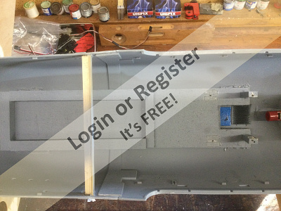
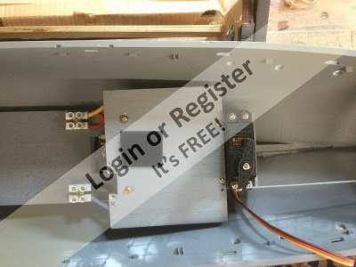
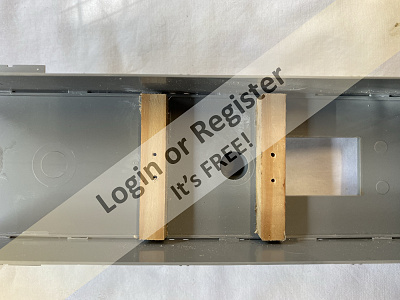
Once this was set I fitted the motor(one I had in the tool box and a 12 volt Howes motor).As the motor is lying on the keel directly it is fixed in with double sided tape so that it can move a little but can be removed for maintenance.
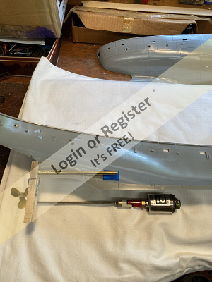
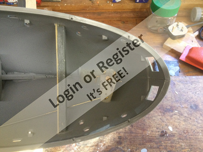
To fully secure it I made using Balsa wood a false deck in which I cut out a hole the size of the motor.This fits around the motor and holds it in place,so no need for a bulky engine mount.
This false deck extends up into the hull and also acts as the solid base that the battery will sit on.
Having completed this then I fitted the motor coupling greased the shaft and did a final fit of that.
I don’t propose the remove the motor and shaft again if I can help it as I have tested under power and they are running well.
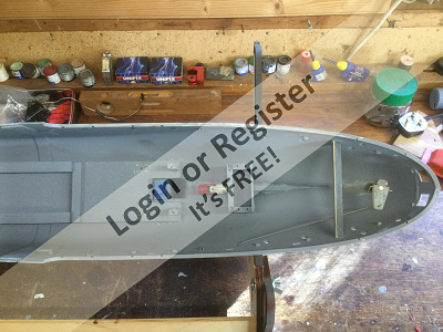
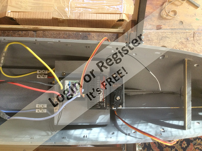
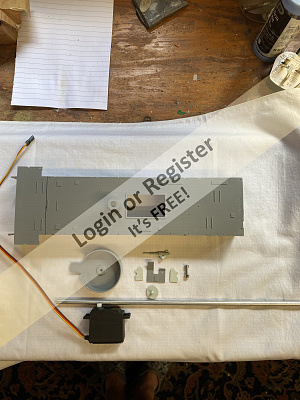
Balsa is a great product and I then build the box for the rudder servo shown in the pictures behind the motor and a suported shelf above the motor on legs that will take the Speed controller and RC RX. These items are all screwed not glued in place so I can remove anything and everything if I need to do maintenance.
( I know some of you will be saying that all the electronics are too close together and I will get interference,but,touch wood after testing and from my previous builds there were no problems🤞🤞)
You will see from the last pictures that I have done dry runs on fitting the rudder servo,speed controller and RX in place and placed the aft deck in place(again dry fitted only at this stage).I hope you can see that it all fits in compactly and still gives me room for some other little goodies that I hope to fit.
In the next post I will show the rudder fitment and servo linkage,simple but effective.
I have also decided now that I will have room to fit a working bilge pump 🤔🤞🤞
Sorry if some of the pictures don’t fall in the right order.
All the wiring is unkempt at the moment and not the finished item😉
Take care all and stay safe.
Regards Bill.


So here I will explain the build process re the above,ie Hull and prop shaft fitment.
Once again I apologise that a lot of this was done prior to taking pre blog pictures.
The Hull comes in four sections,two port and two starboard.(Sorry no pics of separate items)
Having cut them off the sprigs and filing away the rough edges then it is a simple task of joining them together.
I use Revell Contacta Professional glue as recommended but you could use any proprietary plastic glue.
Having joined the relevant sides and allowing to set then I began to offer up the prop shaft prior to joining the port and starboard halves together.
The prop shaft came from Howes and is a 5” M4 Brass tube with Stainless steel shaft.
This length means that I can fit all my internal workings into the mid and aft sections of the hull apart from the battery.This makes everything accessible from the pre formed hole in the aft decking.
You will see in the pictures that I offer up the shaft and motor to the hull and as always I did many dry runs to check that the shaft and motor are as straight as possible.
This ensures less resistance,vibration/noise from the coupling and thus drain on battery.
Happy that all was aligned and square then I glued both hull halves together and left for 24 hours.
Once the hull halves were set then using good old araldite glue I set the shaft in place and poured a good mix around the shaft letting it run into all the cavities.
Again I let it set for 24 hours.
I know a lot of this is teaching Granny to suck eggs,but it may help someone.
Once this was set I fitted the motor(one I had in the tool box and a 12 volt Howes motor).As the motor is lying on the keel directly it is fixed in with double sided tape so that it can move a little but can be removed for maintenance.
To fully secure it I made using Balsa wood a false deck in which I cut out a hole the size of the motor.This fits around the motor and holds it in place,so no need for a bulky engine mount.
This false deck extends up into the hull and also acts as the solid base that the battery will sit on.
Having completed this then I fitted the motor coupling greased the shaft and did a final fit of that.
I don’t propose the remove the motor and shaft again if I can help it as I have tested under power and they are running well.
Balsa is a great product and I then build the box for the rudder servo shown in the pictures behind the motor and a suported shelf above the motor on legs that will take the Speed controller and RC RX. These items are all screwed not glued in place so I can remove anything and everything if I need to do maintenance.
( I know some of you will be saying that all the electronics are too close together and I will get interference,but,touch wood after testing and from my previous builds there were no problems🤞🤞)
You will see from the last pictures that I have done dry runs on fitting the rudder servo,speed controller and RX in place and placed the aft deck in place(again dry fitted only at this stage).I hope you can see that it all fits in compactly and still gives me room for some other little goodies that I hope to fit.
In the next post I will show the rudder fitment and servo linkage,simple but effective.
I have also decided now that I will have room to fit a working bilge pump 🤔🤞🤞
Sorry if some of the pictures don’t fall in the right order.
All the wiring is unkempt at the moment and not the finished item😉
Take care all and stay safe.
Regards Bill.
▲
⟩⟩
GaryLC
Martin555
stevedownunder
redpmg
Rookysailor
Colin H
jbkiwi
|
💬 Re: Hull build.Prop Shaft fitment.
3 years ago by 🇬🇧 Martin555 (
Fleet Admiral)✧ 136 Views · 2 Likes
Flag
Hi Bill,
Nice to see it coming along. Re :- teaching Granny to suck eggs, but it may help someone. It is good that you are thinking about the novice model maker as well as the more advanced. Martin555. ▲
⟩⟩
Scratchbuilder
Colin H
|
|
Login To
Remove Ads 💬 Re: Hull build.Prop Shaft fitment.
3 years ago by 🇬🇧 Scratchbuilder (
Vice Admiral)✧ 139 Views · 2 Likes
Flag
Sorry JB. I’m a bit of a picture straightening Nurd.
Regards Bill ▲
⟩⟩
Martin555
stevedownunder
|
|
💬 Re: Hull build.Prop Shaft fitment.
3 years ago by 🇳🇿 jbkiwi (
Fleet Admiral)✧ 137 Views · 3 Likes
Flag
Unkempt wiring Bill? you obviously haven't seen any of mine ! 😂
JB ▲
⟩⟩
Martin555
stevedownunder
Scratchbuilder
|
📝 HMCS Snowberry 1/72 conversion to HMS Buttercup.
3 years ago by 🇬🇧 Scratchbuilder ( Vice Admiral)
Vice Admiral)✧ 132 Views · 7 Likes · 6 Comments
Flag
💬 Add Comment
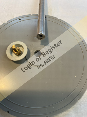
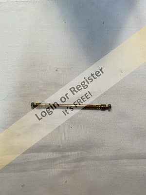
Rudder Assembly.
Evening All.
I previously mentioned that I had no rudder for this model.The reason being that some years ago I stole the Revell rudder from this kit to replace the original rudder on another matchbox Corvett HMS Bluebell that I broke when sailing in dubious conditions.
I contacted Revell asking if I could purchase a replacement but no such luck 😤
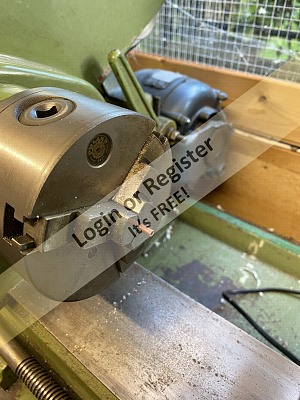
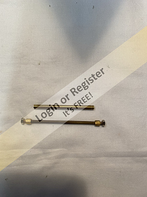
The first two pictures show the kit rudder I stole and fitted to HMS Bluebell which was very easy to convert to live model use by simply turning a rudder post on the lathe and fitting.( If anyone wants help on this please ask and I will contact you and describe)
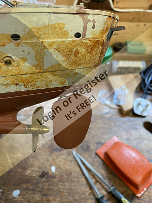
Now I had to make a replacement,and in the absence of any help from Revell I decided to use a large brass rudder which I had in the box and adapt.
The first obvious thing is that the brass rudder is totally the wrong shape.
The blade is riveted to the post so leaving the two rivets in place for strength I cut the blade at the top to as close a shape as the original as possible.
Then gentle filing and shaping gave me a close replacement.
This ensures that the top of the blade follows the hull outline.
I decided to leave the bottom of the blade as it was so that I would retain as much of the surface area as possible.
I am as happy as can be re the shape.
Rudder tube fitted into the hull which means that it is as original as can be.
Araldite was used as the trusty fixing and left to set for 24 hours.
Please note that as per the pictures the rudder when fitted is deliberately close enough to the prop to ensure that should the prop unscrew it will not come off as it will touch the rudder.( Only a fail safe)
This scenario is to be avoided by ensuring that the thread on the prop is opposite to rotation when going ahead so that it will not unscrew.
The last two pictures show a very simple but tried and tested servo connection which gives a very good rudder rotation.
Please note a very important safety pin that I drilled and fitted to ensure that the rudder post does not slip on the servo arm.
The next instalment will be showing a simple but effective bilge pump/engine coolant outflow system which will operate under power.I have done this on my larger boats but not on this scale so it will be fun.
A long way to go yet but slow but sure.
Enjoy.
Regards
Bill.


Evening All.
I previously mentioned that I had no rudder for this model.The reason being that some years ago I stole the Revell rudder from this kit to replace the original rudder on another matchbox Corvett HMS Bluebell that I broke when sailing in dubious conditions.
I contacted Revell asking if I could purchase a replacement but no such luck 😤
The first two pictures show the kit rudder I stole and fitted to HMS Bluebell which was very easy to convert to live model use by simply turning a rudder post on the lathe and fitting.( If anyone wants help on this please ask and I will contact you and describe)
Now I had to make a replacement,and in the absence of any help from Revell I decided to use a large brass rudder which I had in the box and adapt.
The first obvious thing is that the brass rudder is totally the wrong shape.
The blade is riveted to the post so leaving the two rivets in place for strength I cut the blade at the top to as close a shape as the original as possible.
Then gentle filing and shaping gave me a close replacement.
This ensures that the top of the blade follows the hull outline.
I decided to leave the bottom of the blade as it was so that I would retain as much of the surface area as possible.
I am as happy as can be re the shape.
Rudder tube fitted into the hull which means that it is as original as can be.
Araldite was used as the trusty fixing and left to set for 24 hours.
Please note that as per the pictures the rudder when fitted is deliberately close enough to the prop to ensure that should the prop unscrew it will not come off as it will touch the rudder.( Only a fail safe)
This scenario is to be avoided by ensuring that the thread on the prop is opposite to rotation when going ahead so that it will not unscrew.
The last two pictures show a very simple but tried and tested servo connection which gives a very good rudder rotation.
Please note a very important safety pin that I drilled and fitted to ensure that the rudder post does not slip on the servo arm.
The next instalment will be showing a simple but effective bilge pump/engine coolant outflow system which will operate under power.I have done this on my larger boats but not on this scale so it will be fun.
A long way to go yet but slow but sure.
Enjoy.
Regards
Bill.
▲
⟩⟩
RNinMunich
Colin H
jbkiwi
stevedownunder
redpmg
GaryLC
Martin555
|
💬 Re: HMCS Snowberry 1/72 conversion to HMS Buttercup.
3 years ago by 🇬🇧 Scratchbuilder (
Vice Admiral)✧ 118 Views · 1 Like
Flag
Hi Martin.
Thanks for your congratulations on promotion.👍👍 Take care and stay safe. Regards Bill. ▲
⟩⟩
Martin555
|
|
Login To
Remove Ads 💬 Re: HMCS Snowberry 1/72 conversion to HMS Buttercup.
3 years ago by 🇬🇧 Martin555 (
Fleet Admiral)✧ 123 Views · 1 Like
Flag
Hi Captain Scratchbuilder.
How are you getting on with HMS Snowberry any updates ?. Congratulations on your promotion to Captain. Martin555. ▲
⟩⟩
Scratchbuilder
|
|
💬 Re: HMCS Snowberry 1/72 conversion to HMS Buttercup.
3 years ago by 🇬🇧 Scratchbuilder (
Vice Admiral)✧ 130 Views · 3 Likes
Flag
Stephen,Red and Martin.
Thank you. Keeping the linkage simple always works in my book StephenI agree. Sensible thought Red re rudder post support 👍 Your right Martin,took me a lot longer than planed 🤔👍👍 Take care Chaps. Regards Bill ▲
⟩⟩
Martin555
stevedownunder
Colin H
|
|
💬 Re: HMCS Snowberry 1/72 conversion to HMS Buttercup.
3 years ago by 🇦🇺 stevedownunder (
 Captain) Captain)✧ 129 Views · 3 Likes
Flag
Nice job Bill,
I think it is good to keep things like linkages simple, well done. Cheers, Stephen. ▲
⟩⟩
Scratchbuilder
jbkiwi
Martin555
|
|
💬 Re: HMCS Snowberry 1/72 conversion to HMS Buttercup.
3 years ago by 🇿🇦 redpmg (
Commodore)✧ 133 Views · 3 Likes
Flag
At least that rudder wont break Bill - you made a good job of it. The only comment I would make is that perhaps a little strengthening around the base of the rudder inside the hull might be in order just in case there is another bad moment.
Apologies if you feel Im teaching grandmother again............ ▲
⟩⟩
Scratchbuilder
Martin555
stevedownunder
|
|
💬 Re: HMCS Snowberry 1/72 conversion to HMS Buttercup.
3 years ago by 🇬🇧 Martin555 (
Fleet Admiral)✧ 131 Views · 3 Likes
Flag
Nice bit of brass work Bill.
I bet even that little modification took you longer than you thought it would. Good idea using the rudder as a prop retainer. Martin555. ▲
⟩⟩
Scratchbuilder
stevedownunder
GaryLC
|
📝 Bilge Pump installation and voltage regulator.
3 years ago by 🇬🇧 Scratchbuilder ( Vice Admiral)
Vice Admiral)✧ 122 Views · 7 Likes · 9 Comments
Flag
💬 Add Comment
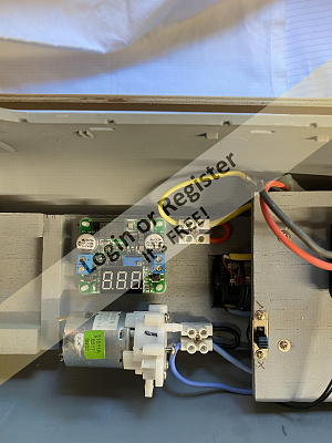
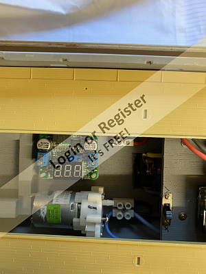
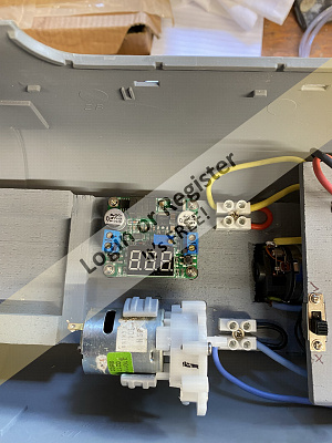
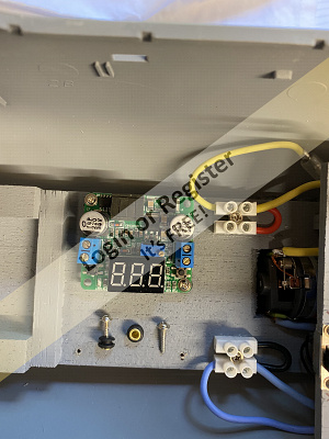
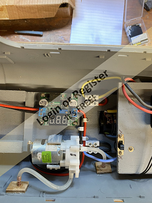
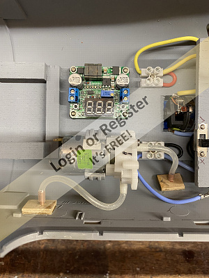
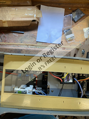
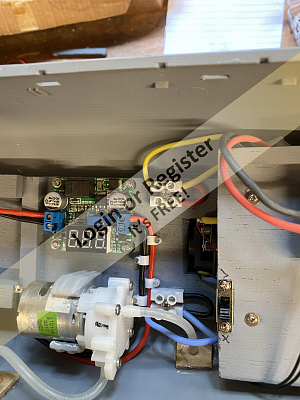
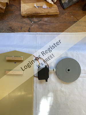
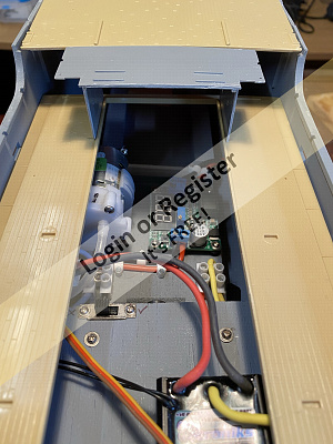
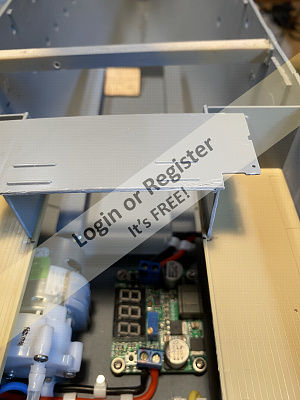
This section deals with the fitting of a mock bilge pump.it’s a bit of fun really and quite literally sucks in water and pumps it out to give the effect of a bilge pump running.
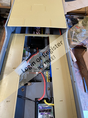
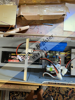
I have done this on my lager boats but not on one this small.I originally said that this 1/72 scale has plenty of room which it has,but there is a lot to pack into the midships/rear hull,and still be in a position to access all the components for maintenance with the deck fully fixed.
In the previous post you will have seen that I left room between the engine and battery bed for this bilge pump section.
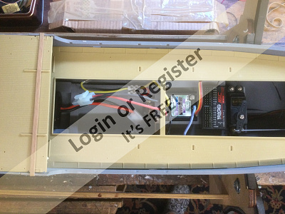
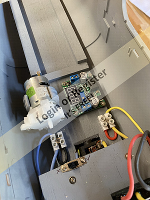
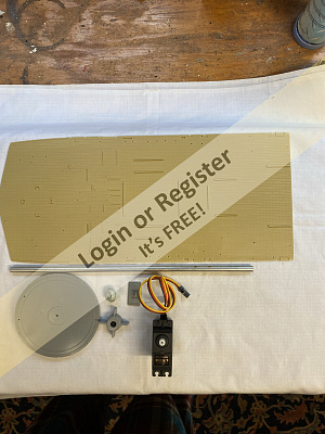
I hope the photos explain the process.The first two only show the parts in a dry run situation with the deck just resting in place to gauge accessibility.
Items used.
All from the magical big box of spare bits and bobs in the shed.
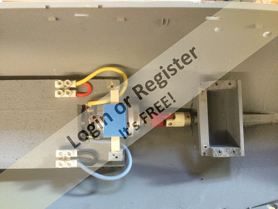
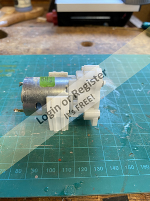
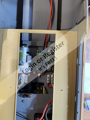
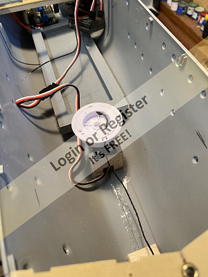
One water pump,voltage range 3 to12 volts.
Voltage step down regulator giving me a range of between 2 to 6 volts,so I can set the pump rate from a dribble to a steady flow by manually adjusting.
2mm copper tube.
3 mm plastic piping.
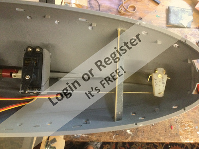
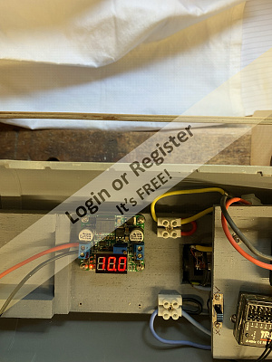
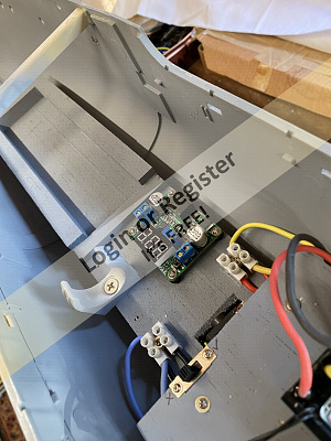
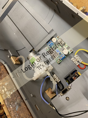
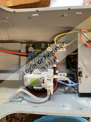
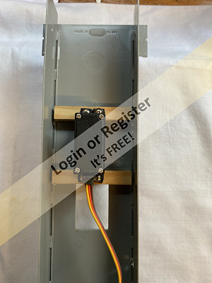
First I fitted the voltage regulator and screwed it down using servo rubber vibration grommets with brass inserts.
Positioning this is important so that the electrical feeds are not compromised.
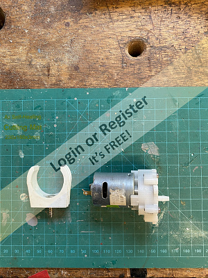
Next I fitted the pump.Now being a difficult shape other than the circular motor I scratched my head to think how to fix it.
Solution a 22mm copper pipe wall fixing from the plumbing box in the garage👍👍
With both these items fitted I next turned two small copper tubes for the inlet and outlet ports.
Next two small wooden strengthening plates were cut and holes drilled for the tubes.
After carefully deciding the ideal height above proposed water line I drilled one hole in the hull and fitted the outlet pipe and backing plates.
The same principle was adopted for the inlet pipe at a random point well below the water line.
Having glued and left for 24 hours I fitted the plastic piping.
Result,the finished pump.
I finally wired the system up and hey presto it works when tested(video will follow)
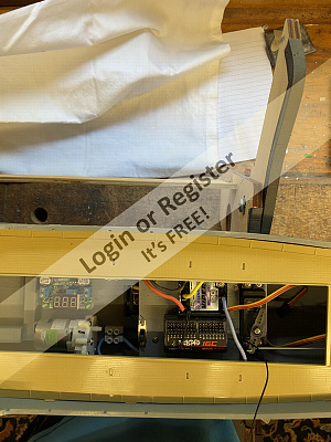
The pump will run off a separate battery (6volt).This battery and Voltage regulator will also power the internal lighting and navigation lights which will follow in due course.
The importance of this is that I have to keep all access to the aperture as shown in the rear deck which will not be removable.
Next will be the start on the rear superstructure.I plan to have the rear guns on a servo as well as the main forward gun.
Time taken 5hours.
Take care and stay safe.
Regards Bill


I have done this on my lager boats but not on one this small.I originally said that this 1/72 scale has plenty of room which it has,but there is a lot to pack into the midships/rear hull,and still be in a position to access all the components for maintenance with the deck fully fixed.
In the previous post you will have seen that I left room between the engine and battery bed for this bilge pump section.
I hope the photos explain the process.The first two only show the parts in a dry run situation with the deck just resting in place to gauge accessibility.
Items used.
All from the magical big box of spare bits and bobs in the shed.
One water pump,voltage range 3 to12 volts.
Voltage step down regulator giving me a range of between 2 to 6 volts,so I can set the pump rate from a dribble to a steady flow by manually adjusting.
2mm copper tube.
3 mm plastic piping.
First I fitted the voltage regulator and screwed it down using servo rubber vibration grommets with brass inserts.
Positioning this is important so that the electrical feeds are not compromised.
Next I fitted the pump.Now being a difficult shape other than the circular motor I scratched my head to think how to fix it.
Solution a 22mm copper pipe wall fixing from the plumbing box in the garage👍👍
With both these items fitted I next turned two small copper tubes for the inlet and outlet ports.
Next two small wooden strengthening plates were cut and holes drilled for the tubes.
After carefully deciding the ideal height above proposed water line I drilled one hole in the hull and fitted the outlet pipe and backing plates.
The same principle was adopted for the inlet pipe at a random point well below the water line.
Having glued and left for 24 hours I fitted the plastic piping.
Result,the finished pump.
I finally wired the system up and hey presto it works when tested(video will follow)
The pump will run off a separate battery (6volt).This battery and Voltage regulator will also power the internal lighting and navigation lights which will follow in due course.
The importance of this is that I have to keep all access to the aperture as shown in the rear deck which will not be removable.
Next will be the start on the rear superstructure.I plan to have the rear guns on a servo as well as the main forward gun.
Time taken 5hours.
Take care and stay safe.
Regards Bill
▲
⟩⟩
stevedownunder
GaryLC
redpmg
Martin555
jbkiwi
RNinMunich
Colin H
|
💬 Re: Bilge Pump installation and voltage regulator.
3 years ago by 🇬🇧 Scratchbuilder (
Vice Admiral)✧ 116 Views · 2 Likes
Flag
Gents.
Thank you all for the kind comments,really appreciated. We are all boys at heart with aching joints and fond memories. Regards Bill 🛳⛴🚢 ▲
⟩⟩
Martin555
RNinMunich
|
|
Login To
Remove Ads 💬 Re: Bilge Pump installation and voltage regulator.
3 years ago by 🇿🇦 redpmg (
Commodore)✧ 125 Views · 3 Likes
Flag
Its coming along nicely Bill - the sight of water pumping out the side of a ship does make it realistic - very good idea - don't go to far and fit BB guns as some US modellers do!! - you'll be like JB next and want smoke & the sound of gunfire from the guns too............
▲
⟩⟩
Scratchbuilder
Martin555
jbkiwi
|
|
💬 Re: Bilge Pump installation and voltage regulator.
3 years ago by 🇩🇪 RNinMunich (
Fleet Admiral)✧ 122 Views · 2 Likes
Flag
Absolutely can't wait to NOT!! see you in your Tutu and tights Bill! 😮
Whoda thought that bilge pumps and ballet dancing could ever meet in the same thread!? I s'pose pumps are the connection😁 Cracking job so far Bill (Nureyev would be proud of you!) Looking forward to the next gizmos. Cheers, Doug 😎 ▲
⟩⟩
Scratchbuilder
Martin555
|
|
💬 Re: Bilge Pump installation and voltage regulator.
3 years ago by 🇬🇧 Scratchbuilder (
Vice Admiral)✧ 117 Views · 2 Likes
Flag
Martin.
You can be so hurtful 🤣🤣🤣🤣🤣 Regards Bill.🤸♀️🤸♂️ ▲
⟩⟩
Martin555
RNinMunich
|
|
💬 Re: Bilge Pump installation and voltage regulator.
3 years ago by 🇬🇧 Martin555 (
Fleet Admiral)✧ 120 Views · 2 Likes
Flag
Bill,
The thought of you as a Ballet Dancer may mean long therapy sessions LOL!! Martin555. ▲
⟩⟩
RNinMunich
Scratchbuilder
|
|
💬 Re: Bilge Pump installation and voltage regulator.
3 years ago by 🇬🇧 Scratchbuilder (
Vice Admiral)✧ 118 Views · 2 Likes
Flag
Hi JB.
Many thanks. Slow but sure.I’m happy at this time. Really enjoying following your blog 👍👍👍 Regards Bill ▲
⟩⟩
jbkiwi
Martin555
|
|
💬 Re: Bilge Pump installation and voltage regulator.
3 years ago by 🇬🇧 Scratchbuilder (
Vice Admiral)✧ 118 Views · 3 Likes
Flag
Thanks Martin.
I did think about cooling the motor,but at the speed my corvette will go the chance of her overheating are about the same as me winning the lottery,or becoming a ballet dancer 😂😂😂😂. Regards Bill👍👍👍 ▲
⟩⟩
stevedownunder
RNinMunich
Martin555
|
|
💬 Re: Bilge Pump installation and voltage regulator.
3 years ago by 🇬🇧 Martin555 (
Fleet Admiral)✧ 123 Views · 2 Likes
Flag
Hi Bill,
She is slowly coming together. Great idea for the motor mount. RE:- Bilge Pump You pump the water in and then out again, have you thought about also using it to keep the motor cool ? Martin555. ▲
⟩⟩
stevedownunder
Scratchbuilder
|
|
💬 Re: Bilge Pump installation and voltage regulator.
3 years ago by 🇳🇿 jbkiwi (
Fleet Admiral)✧ 121 Views · 3 Likes
Flag
Tidy bit of fitting Bill, like your motor mount,-clever idea! Always makes things more realistic if you see water running.
JB ▲
⟩⟩
stevedownunder
Martin555
Scratchbuilder
|
📝 Single aft 2pdr gun build with servo rotation.
3 years ago by 🇬🇧 Scratchbuilder ( Vice Admiral)
Vice Admiral)✧ 116 Views · 9 Likes · 6 Comments
Flag
💬 Add Comment
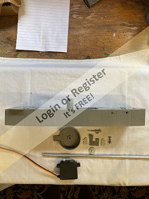
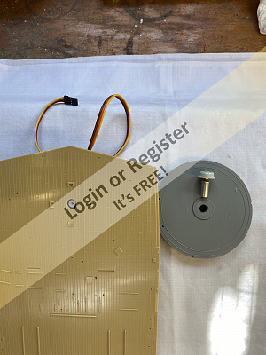
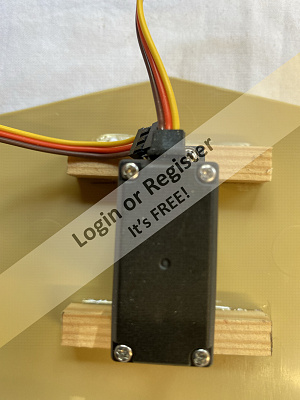
On Saturday I started the construction of the rear superstructure which acts as the base support for various components but in particular the single 2pdr gun.
This shows how I have built the superstructure and used a servo to make a very simple semi rotation system all hidden nicely away inside the superstructure.
Items used.
Superstructure/gun parts from the kit.
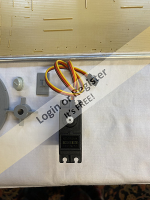
One spare servo.
Aluminium tubing.
3ba nut and bolt.
Spare hard wood for to screw servo too securely.
Pictures 1,2,3,4 simply show the construction of the superstructure as per the instructions.(However the instructions as most tend to go out of the window as I am building the items out of order to suit my needs)
Having taken care when gluing all the components together I left overnight to set in situ on the rear deck,as after modification this will be the only part of the ships hull that will be removable (more on that later).
Building the servo mechanism was simple really and that I find is the best way to keep it.The more problematical you try to make it the more difficult it is to maintain and repair.
If you follow the pictures you will see that I took the plastic base of the 2pdr and removed the plastic nipple point that fits into the gun mount deck.I replaced it with a 3ba screw and glued it in allowing to set.
Taking the aluminium tube I placed it in my lathe Chuck and then pressure fitted the nut into the tube and again glued and allowed to set.
You should see that this allows the gun base to screw into the tubing.
Having cut two lengths of hardwood I glued them to the inside of the superstructure and prepared to fit the servo upside down.
I was lucky that the aluminium tube is just the correct size for a push fit directly onto the servo motor stub 👍👍
Taking a carefull measurement of the length of the tubing having fitted the servo in place I cut to length and turned the end to ensure a-snug fit.
The tubing was then carefully slid onto the servo stub and the gun mounting dropped over the top and the gun base screwed on to the tubing.
This is all easily removable in the event of any breakages.
Gun deck then fitted.
Hey presto it all fits nicely thankfully 👍
The final media file shows the gun rotating nicely.
So a very simple but effective gun mount.
The same principle will be used for the forward 4inch Breech loading in due course.
Please note all the mechanical fitments are being done prior to the fiddly bits.
This also ensures that the basic all up weight is attained ready for the float out and adding of ballast.
Time taken 4hours.
Take care all and stay safe.
Regards Bill.


This shows how I have built the superstructure and used a servo to make a very simple semi rotation system all hidden nicely away inside the superstructure.
Items used.
Superstructure/gun parts from the kit.
One spare servo.
Aluminium tubing.
3ba nut and bolt.
Spare hard wood for to screw servo too securely.
Pictures 1,2,3,4 simply show the construction of the superstructure as per the instructions.(However the instructions as most tend to go out of the window as I am building the items out of order to suit my needs)
Having taken care when gluing all the components together I left overnight to set in situ on the rear deck,as after modification this will be the only part of the ships hull that will be removable (more on that later).
Building the servo mechanism was simple really and that I find is the best way to keep it.The more problematical you try to make it the more difficult it is to maintain and repair.
If you follow the pictures you will see that I took the plastic base of the 2pdr and removed the plastic nipple point that fits into the gun mount deck.I replaced it with a 3ba screw and glued it in allowing to set.
Taking the aluminium tube I placed it in my lathe Chuck and then pressure fitted the nut into the tube and again glued and allowed to set.
You should see that this allows the gun base to screw into the tubing.
Having cut two lengths of hardwood I glued them to the inside of the superstructure and prepared to fit the servo upside down.
I was lucky that the aluminium tube is just the correct size for a push fit directly onto the servo motor stub 👍👍
Taking a carefull measurement of the length of the tubing having fitted the servo in place I cut to length and turned the end to ensure a-snug fit.
The tubing was then carefully slid onto the servo stub and the gun mounting dropped over the top and the gun base screwed on to the tubing.
This is all easily removable in the event of any breakages.
Gun deck then fitted.
Hey presto it all fits nicely thankfully 👍
The final media file shows the gun rotating nicely.
So a very simple but effective gun mount.
The same principle will be used for the forward 4inch Breech loading in due course.
Please note all the mechanical fitments are being done prior to the fiddly bits.
This also ensures that the basic all up weight is attained ready for the float out and adding of ballast.
Time taken 4hours.
Take care all and stay safe.
Regards Bill.
▲
⟩⟩
stevedownunder
jbkiwi
GaryLC
Colin H
Spock66
RNinMunich
Martin555
redpmg
Rookysailor
|
💬 Re: Single aft 2pdr gun build with servo rotation.
3 years ago by 🇳🇿 jbkiwi (
Fleet Admiral)✧ 105 Views · 1 Like
Flag
Good solution Bill👍, tried to look at your movies, but they come out as MOV files and I don't have a converter (I just get the sound)
JB ▲
⟩⟩
stevedownunder
|
|
Login To
Remove Ads 💬 Re: Single aft 2pdr gun build with servo rotation.
3 years ago by 🇬🇧 Spock66 (
Chief Petty Officer 1st Class)✧ 107 Views · 1 Like
Flag
Doug,
You are a bloomin' genius! That has got the creatives working for when I start adding Scnellboot 'bits and bobs'. Thanks so much (a dear friend of mine has seen the article and offered to machine the components (one or two working hands are so much better on a lathe or mill!)). Cheers Andy ▲
⟩⟩
Martin555
|
|
💬 Re: Single aft 2pdr gun build with servo rotation.
3 years ago by 🇩🇪 RNinMunich (
Fleet Admiral)✧ 112 Views · 3 Likes
Flag
Hi Spock,
Nice one👍 All you need now is a synchronised belch of smoke.🔥🌪️ Ran across this article in Model Boats mag showing how to do that. Needs a bit of basic machining but nothing too complicated. Cheers, Doug 😎 
▲
⟩⟩
Spock66
Rookysailor
Martin555
|
|
💬 Re: Single aft 2pdr gun build with servo rotation.
3 years ago by 🇬🇧 Scratchbuilder (
Vice Admiral)✧ 114 Views · 2 Likes
Flag
Hi Spock.
Ummm,now there is an interesting project re the gun noise. Something to give thought to. Thank you. Regards Bill. ▲
⟩⟩
stevedownunder
Martin555
|
|
💬 Re: Single aft 2pdr gun build with servo rotation.
3 years ago by 🇬🇧 Spock66 (
Chief Petty Officer 1st Class)✧ 112 Views · 8 Likes
Flag
Hi Bill,
Congrats, it will be spectacular! As a bit of an addon to Martin555 comment, he's right. From shore side of our boating lake, no-one could see the movement -until! I hid a bright white flashable LED in the shell catcher 'fake' canvas of the 4 pounder with a simple power supply (via main arduino nano), and also used a 'record yourself' card digital chip to record HMS Duncan (type 45) firing her MK8. Then I placed a OO gauge bass speaker in the anchor chest with some tiny holes drilled through the fore deck (sealing the speaker to underside of the deck kept her watertight) and fed the chip output through a simple home made DIY guitar amp to boost the signal. I had to mess around a bit with a 4 contact copper strip under the 4 pounder base to give a 4 position contact point to energise the light and sound. Result? When the gun trained to a group on the pond side, it 'fired' with a flash and bang sound! - caused a fair bit of merriment on Newquay boating lake! They certainly saw it from right across the lake (especially at dusk) and the ducks weren't that happy with the bang to start with. ▲
⟩⟩
stevedownunder
Rookysailor
RNinMunich
Martin555
Scratchbuilder
redpmg
GaryLC
Colin H
|
|
💬 Re: Single aft 2pdr gun build with servo rotation.
3 years ago by 🇬🇧 Martin555 (
Fleet Admiral)✧ 113 Views · 3 Likes
Flag
Hi Bill,
Nice to see you are getting things to work, altho you won't see these things moving from a distance they do look great when on display and other people see her close up. Keep it coming. Martin555. ▲
⟩⟩
stevedownunder
GaryLC
Scratchbuilder
|
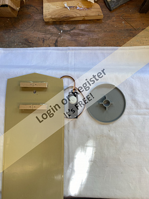
📝 Front 4inch Gun base and servo build.
3 years ago by 🇬🇧 Scratchbuilder ( Vice Admiral)
Vice Admiral)✧ 113 Views · 8 Likes · 3 Comments
Flag
💬 Add Comment
Evening all.
With all the rain we have had today the boat shed has been an inviting place.
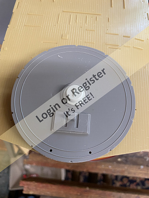
This section is a little bit the same as my previous post as it concerns gun rotation on the front main 4inch gun,but once done I can move onto the next below deck mechanical plan.
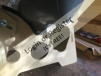
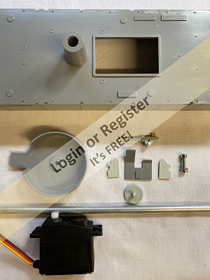
Once again I removed all the parts from the kit needed to build the gun barbette (or stand)and the small support that the actual gun base sits on.
The first pictures show these parts plus the aluminium tube for the servo post and the brass adaptation that I will add to screw into the tube.
I first cut off the small plastic nipple that is the bearing and replace it with a small brass replacement turned on the lathe.
Using good old quick drying araldite I glued the new bearing onto the gun base.
While this is setting then I offered up the nut to one end of the aluminium tube and again using the lathe pushed the nut into it.Some more glue was applied to the nut and allowed to set.
I then enlarged the holes in the barbette and drilled thru the deck.
Offering up the servo to the underside then I cut to length the wooden battens that the servo was to be screwed to.
I then glued the wood to the underside of the deck,but for safety I used four servo screws to screw thru the deck just in axe the glue was to fail.I don’t want the servo falling inside the hull.(These screws will not be seen with the barbette in place)
Having allowed all the glue to set I put it all together and cut the aluminium tube to length and once again thankfully it all works.
The short video just shows the turret base rotating.(The gun will be built and fitted at a later date as will be the painting of the deck prior to final fixing.
Another job done on the road to sorting all the mechanical aspects.
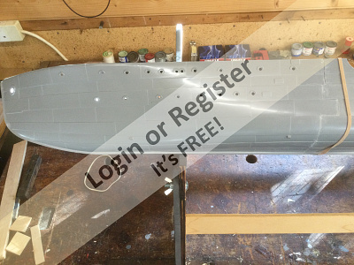
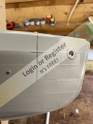
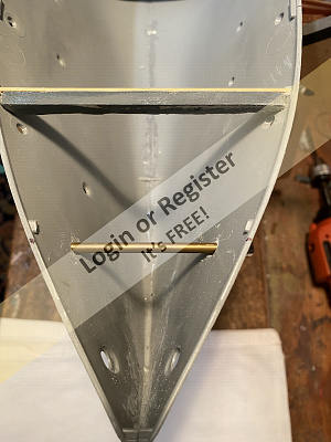
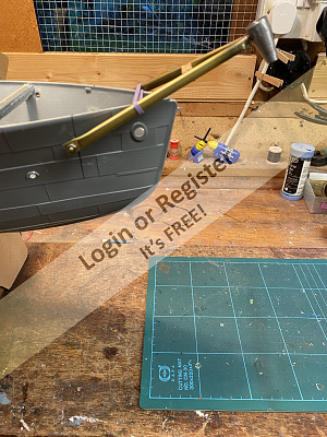
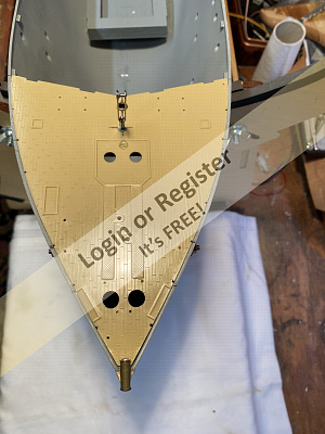
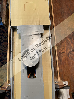
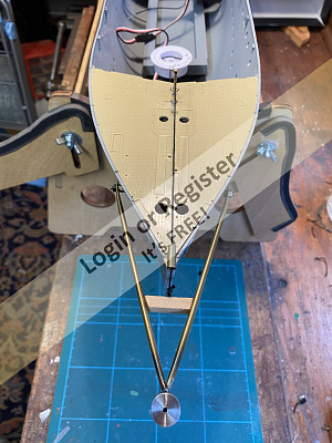
The final picture shows HHS Buttercup bow on.
The next post will involve the making of the acoustic hammer on the bow which I aim to be able to raise and lower.
The acoustic hammer was basically a hammer in a metal bucket which when hanging over the bow was banged with the intention that it set of mines ahead of the ship.
More to follow.
Take care and stay safe everyone.
Time taken on this section of the build 3 hours.
Regards Bill.


With all the rain we have had today the boat shed has been an inviting place.
This section is a little bit the same as my previous post as it concerns gun rotation on the front main 4inch gun,but once done I can move onto the next below deck mechanical plan.
Once again I removed all the parts from the kit needed to build the gun barbette (or stand)and the small support that the actual gun base sits on.
The first pictures show these parts plus the aluminium tube for the servo post and the brass adaptation that I will add to screw into the tube.
I first cut off the small plastic nipple that is the bearing and replace it with a small brass replacement turned on the lathe.
Using good old quick drying araldite I glued the new bearing onto the gun base.
While this is setting then I offered up the nut to one end of the aluminium tube and again using the lathe pushed the nut into it.Some more glue was applied to the nut and allowed to set.
I then enlarged the holes in the barbette and drilled thru the deck.
Offering up the servo to the underside then I cut to length the wooden battens that the servo was to be screwed to.
I then glued the wood to the underside of the deck,but for safety I used four servo screws to screw thru the deck just in axe the glue was to fail.I don’t want the servo falling inside the hull.(These screws will not be seen with the barbette in place)
Having allowed all the glue to set I put it all together and cut the aluminium tube to length and once again thankfully it all works.
The short video just shows the turret base rotating.(The gun will be built and fitted at a later date as will be the painting of the deck prior to final fixing.
Another job done on the road to sorting all the mechanical aspects.
The final picture shows HHS Buttercup bow on.
The next post will involve the making of the acoustic hammer on the bow which I aim to be able to raise and lower.
The acoustic hammer was basically a hammer in a metal bucket which when hanging over the bow was banged with the intention that it set of mines ahead of the ship.
More to follow.
Take care and stay safe everyone.
Time taken on this section of the build 3 hours.
Regards Bill.
▲
⟩⟩
dave976
stevedownunder
Graham93
jbkiwi
Martin555
redpmg
Spock66
Colin H
|
💬 Re: Front 4inch Gun base and servo build.
3 years ago by 🇦🇺 stevedownunder (
Captain)✧ 104 Views · 2 Likes
Flag
Great work Bill,
I like the bilge / circulating pump from your previous post and your animation of guns. Cheers, Stephen. ▲
⟩⟩
Scratchbuilder
Martin555
|
|
Login To
Remove Ads 💬 Re: Front 4inch Gun base and servo build.
3 years ago by 🇳🇿 jbkiwi (
Fleet Admiral)✧ 105 Views · 3 Likes
Flag
Tidy solution Bill, going to look good when all together. Can't see the vids unfortunately as I can't convert Quicktime MOV, .
JB ▲
⟩⟩
stevedownunder
Martin555
Scratchbuilder
|
|
💬 Re: Front 4inch Gun base and servo build.
3 years ago by 🇬🇧 Martin555 (
Fleet Admiral)✧ 107 Views · 2 Likes
Flag
Keep it coming Bill.
I do like these conversions. Martin555. ▲
⟩⟩
stevedownunder
Scratchbuilder
|
📝 Acoustic Hammer construction.Part One.
2 years ago by 🇬🇧 Scratchbuilder ( Vice Admiral)
Vice Admiral)✧ 104 Views · 6 Likes · 5 Comments
Flag
💬 Add Comment
Evening all.
The Acoustic hammer was a device fitted to the bow of some ships including my Corvette conversion.
It was basically a hammer device that made a noise simulating ships engine noise and was hoped would detonate mines ahead of the ship.
When used it was lowered into the water below waterline under the boat.
This part covers the Acoustic hammer.
I hope in the main that the photos self explain the post.
Parts used.
Once again,everything has come from the bits and bobs box or made on the lathe from items in stock.
I have made this as close as I can to the real thing from limited information online including many pictures.
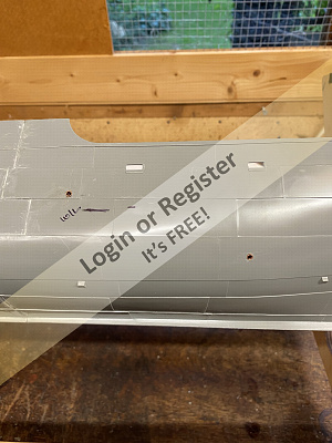
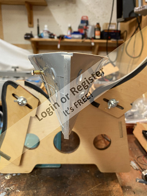
I had to make a suitable bracket that would sit across the bow below the deck.
Firstly I measured and drew lines to show the points where the two holes in both Port and Starboard sides are.
Drilled the holes using a 3mm drill.
Then using 3mm tubing I measured the width and cut the lengths required to span the gap allowing a small protrusion for hull protection.
Ensuring I was happy with this I next cut the 2mm tubing to slide inside the 3mm tube.
This acts as the pivot hinge.
Once again allowing an extra protrusion I turned and threaded the fixing lugs and push fitted them to the 2mm tubing.
This then gave me the entire pivot action.
This done I fixed and glued and allowed to set overnight.
I’m Happy so far👍.
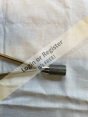
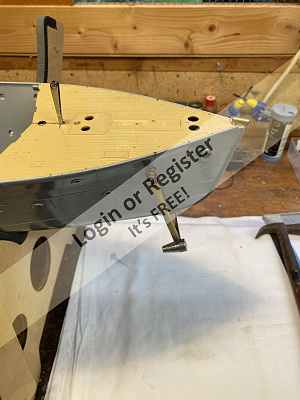
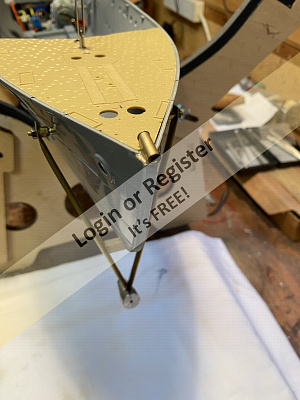
Then I had to make the A frame that hold the acoustic hammer drum and allows the whole device to move up and down.
Made with brass tubing that was cut and then formed to shape I flattened the ends and drilled 2mm holes so that they fitted over my previously turned fixing points.
I then made the actual acoustic hammer drum using an old lead fishing weight by turning it on the lathe and soft soldering it to the A frame.
I need this lead weight to ensure that the whole thing drops easily into the water defying gravity when it operates( See part two)
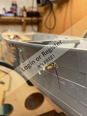
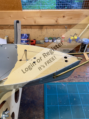
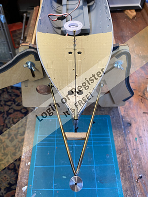
The last photographs show the whole fixing in place with a brass ring fitted to the bull ring position at the bow and an old Aeroplane aileron fixing as the cable mount on the deck behind where the steam anchor winch will be placed,to carry the cable.
You will see the operating cable in place which will be operated by a sail servo winch (I hope).This will be in part Two of this section of the build.
Sorry if this is a little long winded but I hope it explains the end result
Look out for Part two when I hope to make the whole thing work.
Take care all and stay safe.
Time taken on this section 5 hours.
Regards Bill


The Acoustic hammer was a device fitted to the bow of some ships including my Corvette conversion.
It was basically a hammer device that made a noise simulating ships engine noise and was hoped would detonate mines ahead of the ship.
When used it was lowered into the water below waterline under the boat.
This part covers the Acoustic hammer.
I hope in the main that the photos self explain the post.
Parts used.
Once again,everything has come from the bits and bobs box or made on the lathe from items in stock.
I have made this as close as I can to the real thing from limited information online including many pictures.
I had to make a suitable bracket that would sit across the bow below the deck.
Firstly I measured and drew lines to show the points where the two holes in both Port and Starboard sides are.
Drilled the holes using a 3mm drill.
Then using 3mm tubing I measured the width and cut the lengths required to span the gap allowing a small protrusion for hull protection.
Ensuring I was happy with this I next cut the 2mm tubing to slide inside the 3mm tube.
This acts as the pivot hinge.
Once again allowing an extra protrusion I turned and threaded the fixing lugs and push fitted them to the 2mm tubing.
This then gave me the entire pivot action.
This done I fixed and glued and allowed to set overnight.
I’m Happy so far👍.
Then I had to make the A frame that hold the acoustic hammer drum and allows the whole device to move up and down.
Made with brass tubing that was cut and then formed to shape I flattened the ends and drilled 2mm holes so that they fitted over my previously turned fixing points.
I then made the actual acoustic hammer drum using an old lead fishing weight by turning it on the lathe and soft soldering it to the A frame.
I need this lead weight to ensure that the whole thing drops easily into the water defying gravity when it operates( See part two)
The last photographs show the whole fixing in place with a brass ring fitted to the bull ring position at the bow and an old Aeroplane aileron fixing as the cable mount on the deck behind where the steam anchor winch will be placed,to carry the cable.
You will see the operating cable in place which will be operated by a sail servo winch (I hope).This will be in part Two of this section of the build.
Sorry if this is a little long winded but I hope it explains the end result
Look out for Part two when I hope to make the whole thing work.
Take care all and stay safe.
Time taken on this section 5 hours.
Regards Bill
▲
⟩⟩
dave976
Colin H
Newby7
jbkiwi
Martin555
stevedownunder
|
💬 Re: Acoustic Hammer construction.Part One.
2 years ago by 🇬🇧 GaryLC (
Captain)✧ 91 Views · 2 Likes
Flag
Can this be used for swatting those hi-speed nuisance speed boats that come in too close? Regards, Gary.
▲
⟩⟩
stevedownunder
Newby7
|
|
Login To
Remove Ads 💬 Re: Acoustic Hammer construction.Part One.
2 years ago by 🇨🇦 Newby7 (
Fleet Admiral)✧ 95 Views · 3 Likes
Flag
Wonderful writeup Bill. We see it in a flash through your pictures. The writeup shows the time and effort to build the hammer.
Rick ▲
⟩⟩
stevedownunder
Scratchbuilder
Martin555
|
|
💬 Re: Acoustic Hammer construction.Part One.
2 years ago by 🇳🇿 jbkiwi (
Fleet Admiral)✧ 100 Views · 3 Likes
Flag
Interesting and different addition Bill, looks good.
JB ▲
⟩⟩
stevedownunder
Scratchbuilder
Martin555
|
|
💬 Re: Acoustic Hammer construction.Part One.
2 years ago by 🇬🇧 Martin555 (
Fleet Admiral)✧ 107 Views · 2 Likes
Flag
Interesting Bill,
You don't see many model Corvette's with the Hammer fitted. Martin555. ▲
⟩⟩
stevedownunder
Scratchbuilder
|
|
💬 Re: Acoustic Hammer construction.Part One.
2 years ago by 🇦🇺 stevedownunder (
Captain)✧ 104 Views · 2 Likes
Flag
Hi Bill,
Nice work, I wonder what it would have been like inside the hull with that hammer going, not pleasant I guess. Cheers, Stephen. ▲
⟩⟩
Scratchbuilder
Martin555
|
📝 Slight change of sequence due to servo malfunction.
2 years ago by 🇬🇧 Scratchbuilder ( Vice Admiral)
Vice Admiral)✧ 87 Views · 7 Likes · 5 Comments
Flag
💬 Add Comment
Evening All.
Well this should be part 2 of the acoustic hammer concerning the fitting of the sail winch servo,but like all great plans I have had to delay that.
The reason being that on testing my servo I found that it is defective in so much that it won’t work.Having taken it apart and tried to rectify the problem I have decided it is beyond repair 😤🙁.
I can’t take the risk of it going wrong once the deck is sealed in place,so I have ordered a new one and await its delivery.
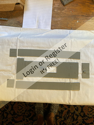
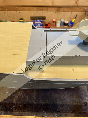
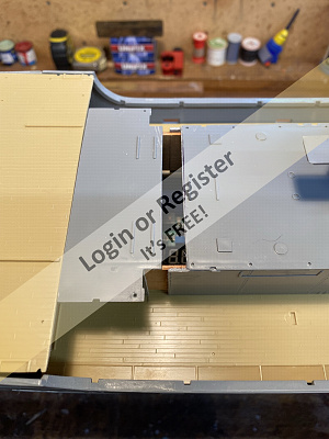
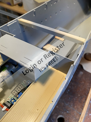
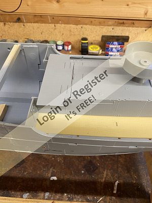
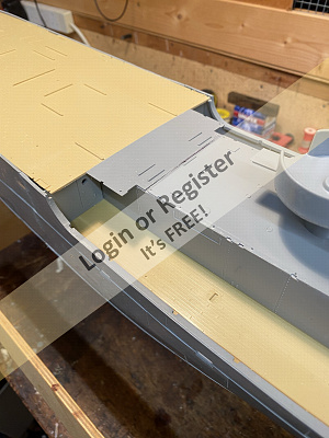
In the meantime I thought I would remodel the rear superstructure engine room casing and gun platform.
As I stated in an earlier post this will be the only part of the upper deck structure that will be removable for battery/wiring connection access.
Once again I hope the pictures paint a thousand words.
Both decks are still only dry fitted.
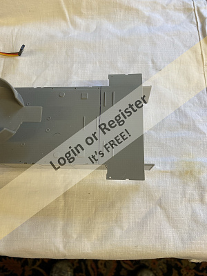
The previously built rear superstructure was placed in situe and marked with a line to show the cut line.
It has to be cut here because the fore deck houses the funnel which also sits on part of the rear superstructure.
It also supports the Carley floats,all too delicate to be continually removed.
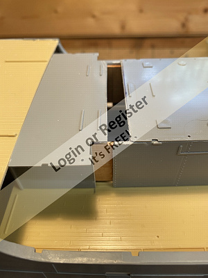
After carefully cutting the section off (and letting my knife slip cutting into the deck annoyingly) I end up with two parts.
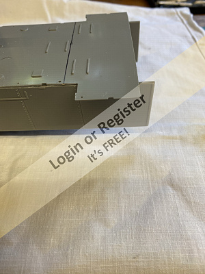
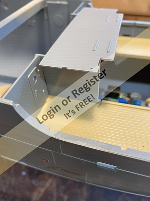
The smaller front section was then glued to the rear deck and fitted up to the front deck to ensure everything fits in place.
I then glued the access bulkheads to the inner ship to the side of the smaller section to give extra strength to this delicate part.
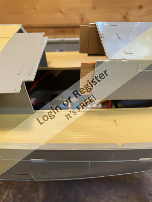
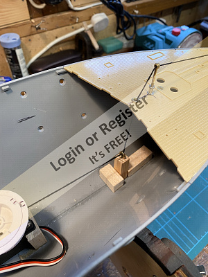
I then added some small hardwood battens to the interior of the larger section,glued, and allowed to set.These will act as guides to ensure the superstructure slides into place easily without damage.
The final pictures show the structure in place.
So an unplanned part done,but good to get it out of the way.
Just await the new servo now and once that is in place I can start to think about tank tests to get the correct ballast prior to fixing the decks in place.
Stay safe and take care.
Regards Bill
Well this should be part 2 of the acoustic hammer concerning the fitting of the sail winch servo,but like all great plans I have had to delay that.
The reason being that on testing my servo I found that it is defective in so much that it won’t work.Having taken it apart and tried to rectify the problem I have decided it is beyond repair 😤🙁.
I can’t take the risk of it going wrong once the deck is sealed in place,so I have ordered a new one and await its delivery.
In the meantime I thought I would remodel the rear superstructure engine room casing and gun platform.
As I stated in an earlier post this will be the only part of the upper deck structure that will be removable for battery/wiring connection access.
Once again I hope the pictures paint a thousand words.
Both decks are still only dry fitted.
The previously built rear superstructure was placed in situe and marked with a line to show the cut line.
It has to be cut here because the fore deck houses the funnel which also sits on part of the rear superstructure.
It also supports the Carley floats,all too delicate to be continually removed.
After carefully cutting the section off (and letting my knife slip cutting into the deck annoyingly) I end up with two parts.
The smaller front section was then glued to the rear deck and fitted up to the front deck to ensure everything fits in place.
I then glued the access bulkheads to the inner ship to the side of the smaller section to give extra strength to this delicate part.
I then added some small hardwood battens to the interior of the larger section,glued, and allowed to set.These will act as guides to ensure the superstructure slides into place easily without damage.
The final pictures show the structure in place.
So an unplanned part done,but good to get it out of the way.
Just await the new servo now and once that is in place I can start to think about tank tests to get the correct ballast prior to fixing the decks in place.
Stay safe and take care.
Regards Bill
▲
⟩⟩
jbkiwi
Newby7
GaryLC
Martin555
stevedownunder
dave976
Colin H
|
💬 Re: Slight change of sequence due to servo malfunction.
2 years ago by 🇬🇧 Scratchbuilder (
Vice Admiral)✧ 81 Views · 3 Likes
Flag
Gents.
Thank you for the comments all of which are valued. I’m never to old to learn and proud to admit it. Stephen I agree re the accessibility of all parts,and you have got me thinking🤔 To that end I know I can get at everything in the aft section of the boat so I don’t have a worry there. The two servos forward will worry me if inaccessible,so I am taking advice and going to think of a way to ensure I can get to the front turret and acoustic hammer components Update on that in due course. Dave thanks for the info on the hammer link. Everything helps and interesting reading. Take care all. Regards Bill. ▲
⟩⟩
dave976
Martin555
stevedownunder
|
|
Login To
Remove Ads 💬 Re: Slight change of sequence due to servo malfunction.
2 years ago by 🇨🇦 Newby7 (
Fleet Admiral)✧ 79 Views · 3 Likes
Flag
Sorry to hear about the servo Bill better now then if it was in the finished boat. Nice work on the fit .
Rick ▲
⟩⟩
stevedownunder
Martin555
Scratchbuilder
|
|
💬 Re: Slight change of sequence due to servo malfunction.
2 years ago by 🇬🇧 dave976 (
Captain)✧ 91 Views · 3 Likes
Flag
I was intrigued by this piece of armament so looked it up and found this site
▲
⟩⟩
stevedownunder
Martin555
Scratchbuilder
|

|
💬 Re: Slight change of sequence due to servo malfunction.
2 years ago by 🇬🇧 Martin555 (
Fleet Admiral)✧ 100 Views · 3 Likes
Flag
Hi Bill,
Re servo :- I had a similar situation that when the forward deck was fitted on HMS Cottesmore i would not be able to undo the securing screws that would hold down the servo. So i made a snug fitting box that surrounded the servo and then cut a slot down the back part for the cable to slide down. When the servo is inserted it stayed nicely in place. The servo arm had two pins fitted that lined up with another servo arm that controlled the main gun. I hope this makes some sort of sense if not then just give me a shout. PS. Nice work. Martin555. ▲
⟩⟩
stevedownunder
Scratchbuilder
GaryLC
|
|
💬 Re: Slight change of sequence due to servo malfunction.
2 years ago by 🇦🇺 stevedownunder (
Captain)✧ 87 Views · 3 Likes
Flag
Hi Bill,
Great progress, better to find out about the faulty servo now than later. I know it is your choice and your model but personally I don't like permanently fitting working items. Cheers, Stephen. ▲
⟩⟩
Scratchbuilder
GaryLC
Martin555
|
📝 Acoustic Hammer Part 2
2 years ago by 🇬🇧 Scratchbuilder ( Vice Admiral)
Vice Admiral)✧ 60 Views · 6 Likes · 4 Comments
Flag
💬 Add Comment
Afternoon all.
As I previously stated this update was delayed by the discovery that my one and only sail servo was not very healthy so I had to await the arrival of a new one.
Having taken charge of said 1.5 turn servo it was a case of fitting and adjusting.
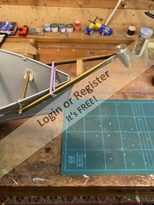
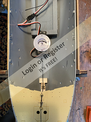
If you go back to part 1 you can see that the device itself was made and fitted for a dry run.I attached some plyable but strong thread and ran it thru the various eyelets I have made so that it disappeared below decks.
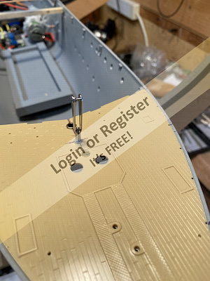
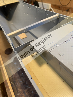
Once again the few pictures show the story of below deck construction.
I simply fitted one end of the servo to the forward end of the motor battery box and made a further support upright.
This upright was glued to the internal hull and allowed to set.
Directly below the eyelet where the thread passes thru the deck I made another balsa support and screwed in a brass runner so that the thread can run freely.
There is a reason for doing it this way and not letting the thread run at an angle directly to the deck eyelet. This is so that when the deck is in place the main front gun servo will not snag on it,as it sits just above it.
I am deliberately keeping all these servos as close as possible because thanks to relevant advice from others and second thoughts on my part I will be cutting a section in the deck to allow access for maintenance.
Having allowed all the supports to dry I finally cut and tied off the thread and tested the system.
It all works and I am happy with this section,although like all of us I am scratching my head and wondering if it could be better.
I hope you are able to view the short video of the hammer working but I am aware that some can’t….sorry.
It’s only a short clip as the other file was too large.
Moving on to the next part soon and thinking………Shall I fit a servo to one of the anchors as I bought two sail servos 🤔🤔.
Take care all and stay safe.
Regards Bill.

As I previously stated this update was delayed by the discovery that my one and only sail servo was not very healthy so I had to await the arrival of a new one.
Having taken charge of said 1.5 turn servo it was a case of fitting and adjusting.
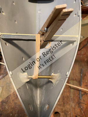
If you go back to part 1 you can see that the device itself was made and fitted for a dry run.I attached some plyable but strong thread and ran it thru the various eyelets I have made so that it disappeared below decks.
Once again the few pictures show the story of below deck construction.
I simply fitted one end of the servo to the forward end of the motor battery box and made a further support upright.
This upright was glued to the internal hull and allowed to set.
Directly below the eyelet where the thread passes thru the deck I made another balsa support and screwed in a brass runner so that the thread can run freely.
There is a reason for doing it this way and not letting the thread run at an angle directly to the deck eyelet. This is so that when the deck is in place the main front gun servo will not snag on it,as it sits just above it.
I am deliberately keeping all these servos as close as possible because thanks to relevant advice from others and second thoughts on my part I will be cutting a section in the deck to allow access for maintenance.
Having allowed all the supports to dry I finally cut and tied off the thread and tested the system.
It all works and I am happy with this section,although like all of us I am scratching my head and wondering if it could be better.
I hope you are able to view the short video of the hammer working but I am aware that some can’t….sorry.
It’s only a short clip as the other file was too large.
Moving on to the next part soon and thinking………Shall I fit a servo to one of the anchors as I bought two sail servos 🤔🤔.
Take care all and stay safe.
Regards Bill.
▲
⟩⟩
jbkiwi
redpmg
stevedownunder
RNinMunich
dave976
Martin555
|
💬 Re: Acoustic Hammer Part 2
2 years ago by 🇬🇧 Scratchbuilder (
Vice Admiral)✧ 49 Views · 2 Likes
Flag
Hi Stephen.
Your right 👍.I have a cunning plan to cut the foredeck just behind the forward gun. I will then screw it to below deck brackets. This will not affect any of the deck furniture. I will do a section on it after the weekend. Thank you for your interest and input. Regards Bill. ▲
⟩⟩
stevedownunder
Martin555
|
|
Login To
Remove Ads 💬 Re: Acoustic Hammer Part 2
2 years ago by 🇦🇺 stevedownunder (
Captain)✧ 47 Views · 3 Likes
Flag
Hi Bill,
Looking good, maybe your extra removable deck section could be of a semi-permanent sort held in place with tiny screws or something. Cheers, Stephen. ▲
⟩⟩
Scratchbuilder
Martin555
GaryLC
|
|
💬 Re: Acoustic Hammer Part 2
2 years ago by 🇬🇧 Scratchbuilder (
Vice Admiral)✧ 59 Views · 2 Likes
Flag
Hi Martin.
Good point,and as I have said in the past two heads are better than one !! As a result back to the workshop to attach a small Brass stop at the point of contact which resolved your point 👍. At the same time I added a small Brass V shaped guide to the bow so that the thread doesn’t slide to either side which it was on occasions and certainly would have under way. See attached. Thank you. Regards Bill 
▲
⟩⟩
Martin555
stevedownunder
|
|
💬 Re: Acoustic Hammer Part 2
2 years ago by 🇬🇧 Martin555 (
Fleet Admiral)✧ 80 Views · 4 Likes
Flag
Hi Bill,
It's good to see things working. If the boat is in forward motion and the hammer is lowered it will be forced back into the hull so will/have you fitted a stop or bracket under the boat to stop the strain on the servo? Martin555. ▲
⟩⟩
GaryLC
stevedownunder
Scratchbuilder
RNinMunich
|


Login To
Remove Ads
Remove Ads