Join Us On Social Media!

|

|

|
Download The App!
Login To
Remove Ads
Remove Ads
Login To
Remove Ads
Remove Ads
Model Boats Website
Vintage Model Works Thames Police Launch by M Turpin
52 Posts · 23 Followers · 393 Photos · 415 Likes
Began 4 years ago by
 United Kingdom
Follow This Thread
Not currently following
> Click to follow
> Click to follow
Latest Post 3 years ago by
| Oldest posts shown first (Show Newest First) | (Print Booklet) |
📝 Vintage Model Works Thames Police Launch by M Turpin
4 years ago by 🇬🇧 mturpin013 ( Admiral)
Admiral)✧ 146 Views · 9 Likes · 8 Comments
Flag
💬 Add Comment
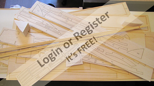
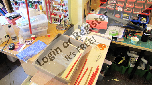
Check all parts are present
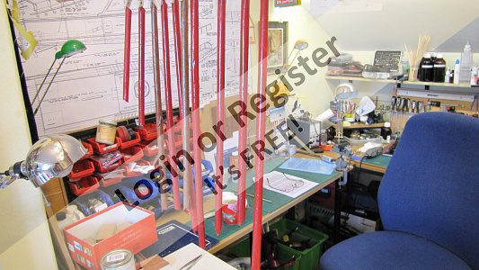
I decided my next build would be from Vintage Model Works as I was pleased with my last build - the 46" Crash Tender, which I have to say hasn't seen water yet due to the dreaded virus.
What a delight opening a new kit, that slightly smokey smell of laser cut ply and balsa wood. The parts are listed in order of material type, balsa/ply/white metal. A quick count of each section confirmed all the parts were present and correct. The plan caused some concern as I didn’t have a wall big enough to pin it up. So first I decided to tape the two sheets together, I observed that at the overlap point some of the text was on one sheet and not on the other so when taped together some text was lost, but this was easily remedied by cutting a rather irregular cut line during the joining process. Issue overcome, now to solve the wall issue. The border around the plan was generous to say the least so I removed this making the sheet more manageable (I still ended up folding a corner along the ceiling.
The instruction sheet supplied has I believe been updated from the original as written by Phil Smith, and at first read looks quite comprehensive, however your never sure of a set of instruction being read and making sense without your hands on the pieces and a bottle of glue in hand (it’s about getting in “The Zone”) so on with the build.
* The picture is borrowed from a museum item
▲
⟩⟩
Colin H
Inkoust
stevedownunder
MouldBuilder
Martin555
Joe727
ianed57
marky
RNinMunich
|
💬 Re: Vintage Model Works Thames Police Launch by M Turpin
4 years ago by 🇬🇧 robbob (
Admiral)✧ 141 Views · 2 Likes
Flag
Hi Mike.
You may have to source the bits you need from various HobbyKing warehouses wherever they are in stock as I did, or consider some other UK manufacturer or supplier. Try looking on Bangood for some of the HobbyKing equivalents that they do ? Meanwhile you've got some building to keep you busy 😁 Rob. ▲
⟩⟩
hmsnostalgia
Martin555
|
|
Login To
Remove Ads 💬 Re: Vintage Model Works Thames Police Launch by M Turpin
4 years ago by 🇭🇺 MouldBuilder (
 Vice Admiral) Vice Admiral)✧ 141 Views · 2 Likes
Flag
Looking forward to this one Mike😄.
Your Crash Tender is a superb model especially with all of the improvements you made along the way. I will start mine next year and will use your build log as a guide.👏 ▲
⟩⟩
Martin555
RNinMunich
|
|
💬 Re: Vintage Model Works Thames Police Launch by M Turpin
4 years ago by 🇬🇧 mturpin013 (
Admiral)✧ 141 Views · 2 Likes
Flag
Hi Rob unfortunately they are all on back order with Hobbyking so I may have to go elsewhere if they don't come up with the goods soon.
Any suggestions welcome ▲
⟩⟩
Martin555
robbob
|
|
💬 Re: Vintage Model Works Thames Police Launch by M Turpin
4 years ago by 🇬🇧 Martin555 (
 Fleet Admiral) Fleet Admiral)✧ 141 Views · 0 Likes
Flag
Hi Mike,
I too will be following your build log. Already looking forward to the next update. Martin555. ▲
⟩⟩
No likes yet
This member will receive 1 point for every like received |
|
💬 Re: Vintage Model Works Thames Police Launch by M Turpin
4 years ago by 🇬🇧 robbob (
Admiral)✧ 142 Views · 3 Likes
Flag
Hi Mike.
Good to see that you've started your Police Boat build and the blog, I'll be following with great interest 👍😀 I hope my build blog will be helpful but I don't think you'll have any problems with this build.The Vintage Model Works kits are very easy to put together and hopefully the instructions have been revised a bit since my test build. Have you managed to get the running gear for it yet (motor, ESC, RX, Batteries etc) they seem to be in very short supply at the moment? Rob. ▲
⟩⟩
hmsnostalgia
MouldBuilder
Martin555
|
|
💬 Re: Vintage Model Works Thames Police Launch by M Turpin
4 years ago by 🇩🇪 RNinMunich (
Fleet Admiral)✧ 142 Views · 3 Likes
Flag
Hi CB,
Commodore Robbob built the prototype Police Launch a little while ago at the request of VMW. He proposed improvements to the kit and the instructions to VMW and wrote an excellent Blog of his build. You can find it here. ▲
⟩⟩
hmsnostalgia
MouldBuilder
Martin555
|
|
💬 Re: Vintage Model Works Thames Police Launch by M Turpin
4 years ago by 🇬🇧 CB90 (
 Commander) Commander)✧ 141 Views · 1 Like
Flag
I found another one on our site, and a video from way back.
▲
⟩⟩
Martin555
|
|
💬 Re: Vintage Model Works Thames Police Launch by M Turpin
4 years ago by 🇬🇧 marky (
 Commodore) Commodore)✧ 141 Views · 1 Like
Flag
Looking forward to another exciting build.
Cheers Marky👍 ▲
⟩⟩
Martin555
|
Login To
Remove Ads
Remove Ads
📝 The Box
4 years ago by 🇬🇧 mturpin013 ( Admiral)
Admiral)✧ 152 Views · 9 Likes · 4 Comments
Flag
💬 Add Comment
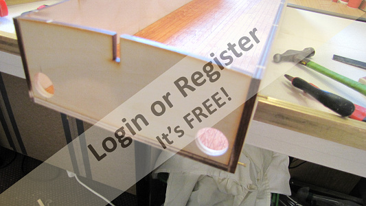
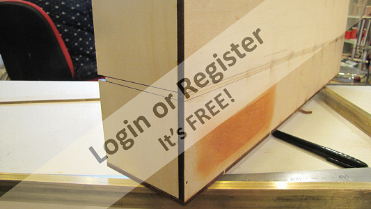
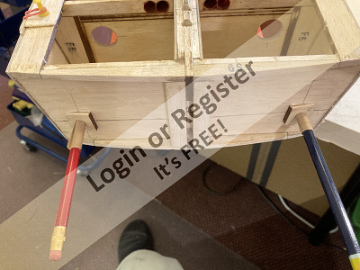
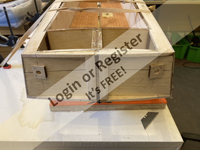
As I read the build of another member who did the prototype build of this kit (Robbob) I saw that a number of the parts that were originally in balsa had been changed to ply, a good modification in my mind as this “box” seems to form the backbone of the construction and the motor is mounted on this deck so needs to be strong.
The parts for the box are all laser cut and to very fine tolerances and the gap that’s left by the cut is minimal to say the least. I found Even a craft knife was too thick to slide into the laser cut so the best way to release the pieces was to use an old artist palette knife and just tap each joint which separates the parts quite easily, all that needs to be done then is to sand away the excess bump left by the joint.
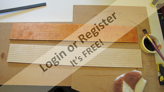
The base of the box has planking marked out (laser etched) which is a great help if you don’t like planking a deck (although I do and maybe will plank it myself).
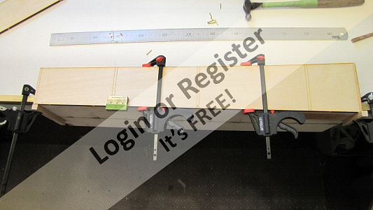
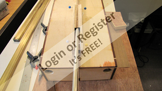
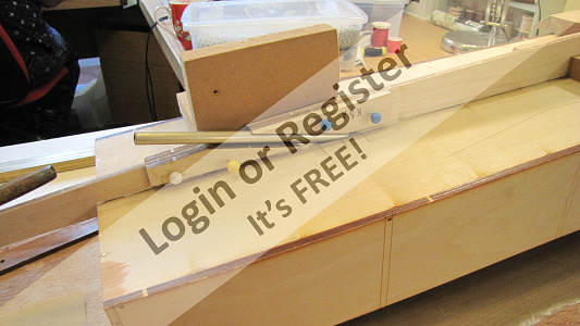
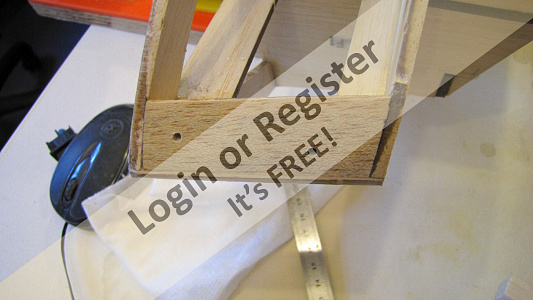
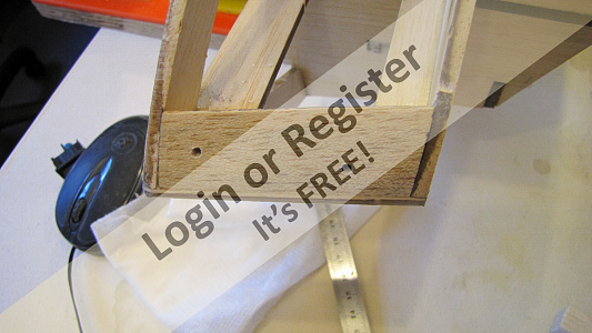
It is in 2 halves which need to be joined together, so a flat surface is required. The join needs to be tight so I decided to make a jig that that could apply even pressure to the 2 halves whilst setting, it’s simply three wedges that when tapped in will apply a great pressure to the joint.
The back bulkhead (F 6 ) will need wires to pass through, so at this point it’s easier to put 2 x 25mm holes in this bulkhead rather than when its constructed also in F1 for wires to the battery and switch.
I will be using aliphatic glue on most of the joints so for this joint I laid a sheet of PTFE oven baking sheet on the flat board so the glue doesn’t stick to the board, a bead of glue was applied along one side and then the other half is offered up. Once aligned, the three wedges are gently tapped until glue oozes out of the joint, I use a damp cloth to remove any excess glue from the surface as I don’t want it to contaminate the surface before any stain is applied.
Once dry the base can be stained and then the sides can be prepared.
As this is ply I will be using some 0.5 brass pins to assist in joining.
Again I like a jig to assist the process so a piece of brass bar is machined with a right angle then holes are drilled to accommodate 4,5 and 6 mm ply so a pilot hole can be drilled for the brass pins ensuring they go straight and in the middle of the ply.
I mount the two pieces to be joined on a piece of square brass bar to ensure the base and sides are kept square.
After drilling, a bead of glue is applied and then the pieces aligned and then clamped together and finally the pins are tapped home, this is repeated for the remaining side and ends.
The whole assembly is then checked for squareness before the glue starts to set with all sides square its left to set


The parts for the box are all laser cut and to very fine tolerances and the gap that’s left by the cut is minimal to say the least. I found Even a craft knife was too thick to slide into the laser cut so the best way to release the pieces was to use an old artist palette knife and just tap each joint which separates the parts quite easily, all that needs to be done then is to sand away the excess bump left by the joint.
The base of the box has planking marked out (laser etched) which is a great help if you don’t like planking a deck (although I do and maybe will plank it myself).
It is in 2 halves which need to be joined together, so a flat surface is required. The join needs to be tight so I decided to make a jig that that could apply even pressure to the 2 halves whilst setting, it’s simply three wedges that when tapped in will apply a great pressure to the joint.
The back bulkhead (F 6 ) will need wires to pass through, so at this point it’s easier to put 2 x 25mm holes in this bulkhead rather than when its constructed also in F1 for wires to the battery and switch.
I will be using aliphatic glue on most of the joints so for this joint I laid a sheet of PTFE oven baking sheet on the flat board so the glue doesn’t stick to the board, a bead of glue was applied along one side and then the other half is offered up. Once aligned, the three wedges are gently tapped until glue oozes out of the joint, I use a damp cloth to remove any excess glue from the surface as I don’t want it to contaminate the surface before any stain is applied.
Once dry the base can be stained and then the sides can be prepared.
As this is ply I will be using some 0.5 brass pins to assist in joining.
Again I like a jig to assist the process so a piece of brass bar is machined with a right angle then holes are drilled to accommodate 4,5 and 6 mm ply so a pilot hole can be drilled for the brass pins ensuring they go straight and in the middle of the ply.
I mount the two pieces to be joined on a piece of square brass bar to ensure the base and sides are kept square.
After drilling, a bead of glue is applied and then the pieces aligned and then clamped together and finally the pins are tapped home, this is repeated for the remaining side and ends.
The whole assembly is then checked for squareness before the glue starts to set with all sides square its left to set
▲
⟩⟩
Colin H
MouldBuilder
Rowen
Inkoust
ianed57
stevedownunder
robbob
marky
Martin555
|
💬 Re: The Box
4 years ago by 🇬🇧 mturpin013 (
Admiral)✧ 148 Views · 2 Likes
Flag
So right Rob I will probably plank all appropriate surfaces, I quite enjoy planking
▲
⟩⟩
Martin555
robbob
|
|
Login To
Remove Ads 💬 Re: The Box
4 years ago by 🇬🇧 marky (
Commodore)✧ 148 Views · 1 Like
Flag
Great tip with the wedges ,look forward to the rest of the build
▲
⟩⟩
Martin555
|
|
💬 Re: The Box
4 years ago by 🇬🇧 robbob (
Admiral)✧ 149 Views · 3 Likes
Flag
Hi Mike.
The change to ply for the box is a good move by VMW and the laser etched planking will save a lot of time for many modelers as planking the inside of a box ain't easy 😮. The downside is that the heavy grain of the birch ply spoils the effect which is why real planking with a random grain patterns looks so much better. I used sheets of obeche which has a smaller and less pronounced grain pattern and drew the planking lines on for the floor of the box and real obeche planking and caulking for the deck. More time consuming but so much better. 😁 Rob. ▲
⟩⟩
hmsnostalgia
Martin555
marky
|
|
💬 Re: The Box
4 years ago by 🇬🇧 Martin555 (
Fleet Admiral)✧ 148 Views · 1 Like
Flag
After following your previous builds i am sure this one will be as great.
I bet you will be glad when you get to the more interesting parts. Keep up the good work. Martin555. ▲
⟩⟩
stevedownunder
|
📝 The keel
4 years ago by 🇬🇧 mturpin013 ( Admiral)
Admiral)✧ 150 Views · 7 Likes · 7 Comments
Flag
💬 Add Comment
The Keel this is made up from 3 pieces and according to the instructions should be placed on the drawing to be glued together.
However the parts are so accurate they can be put together just making sure the joint is pressed together and glued, using some backing sheet to avoid sticking to the board.
It is still in 2 pieces; the longest from the bow to the prop shaft hole and the short piece from the hole to the stern.
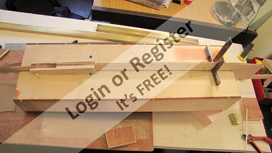
At this point I decided to drill the 8mm hole for the propeller shaft, so that I was sure it lined up with the keel parts. After the longest piece has set it can be glued to the box section, it has to butt up against the front of the box, which puts the keel in the correct position.
Before the glue sets its important to make sure its square on the box.
The rear piece is also glued into position. Around the propeller shaft exit point there are some extra pieces added to give some more support to the prop shaft.
The whole assembly is left to set overnight.


However the parts are so accurate they can be put together just making sure the joint is pressed together and glued, using some backing sheet to avoid sticking to the board.
It is still in 2 pieces; the longest from the bow to the prop shaft hole and the short piece from the hole to the stern.
At this point I decided to drill the 8mm hole for the propeller shaft, so that I was sure it lined up with the keel parts. After the longest piece has set it can be glued to the box section, it has to butt up against the front of the box, which puts the keel in the correct position.
Before the glue sets its important to make sure its square on the box.
The rear piece is also glued into position. Around the propeller shaft exit point there are some extra pieces added to give some more support to the prop shaft.
The whole assembly is left to set overnight.
▲
⟩⟩
Colin H
MouldBuilder
stevedownunder
Skydive130
Martin555
marky
robbob
|
💬 Re: The keel
4 years ago by 🇬🇧 mturpin013 (
Admiral)✧ 148 Views · 1 Like
Flag
Will do Feet oops! Fleet😁.
Now wheres that dam switch ▲
⟩⟩
robbob
|
|
Login To
Remove Ads 💬 Re: The keel
4 years ago by 🇩🇪 RNinMunich (
Fleet Admiral)✧ 149 Views · 1 Like
Flag
Above all Mike,
SWITCH OFF THAT DAMN STUPID AUTO-CORRECTION!! You know what you want to say, IT doesn't😉 Cheers, Doug 😎 ▲
⟩⟩
Joe727
|
|
💬 Re: The keel
4 years ago by 🇬🇧 mturpin013 (
Admiral)✧ 148 Views · 1 Like
Flag
No not really. sorry (read before final post)
▲
⟩⟩
RNinMunich
|
|
💬 Re: The keel
4 years ago by 🇩🇪 RNinMunich (
Fleet Admiral)✧ 148 Views · 0 Likes
Flag
"reviled "!!
Is it gonna be THAT bad Mike?🤔 I'm sure we'll all be a little more polite than that.😊 Hm, maybe not😁 😎 ▲
⟩⟩
No likes yet
This member will receive 1 point for every like received |
|
💬 Re: The keel
4 years ago by 🇬🇧 robbob (
Admiral)✧ 148 Views · 2 Likes
Flag
'Reviled'.......really🤔
▲
⟩⟩
hmsnostalgia
RNinMunich
|
|
💬 Re: The keel
4 years ago by 🇬🇧 mturpin013 (
Admiral)✧ 149 Views · 1 Like
Flag
Yes it is all will be revealed soon
▲
⟩⟩
MouldBuilder
|
|
💬 Re: The keel
4 years ago by 🇭🇺 MouldBuilder (
Vice Admiral)✧ 148 Views · 2 Likes
Flag
Great start Mike.
Sorry for being a bit thick but is the hull built around this box. Peter. ▲
⟩⟩
RNinMunich
Martin555
|
📝 Adding the bulkhead formers
4 years ago by 🇬🇧 mturpin013 ( Admiral)
Admiral)✧ 153 Views · 9 Likes · 12 Comments
Flag
💬 Add Comment
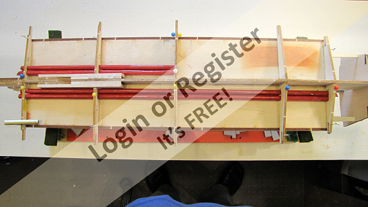
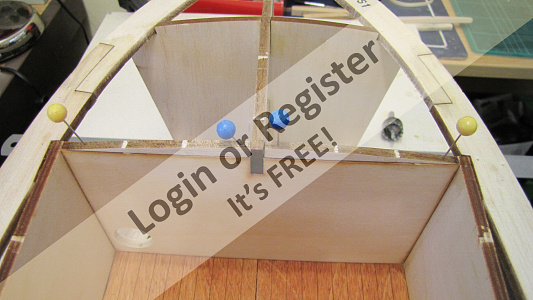
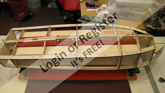
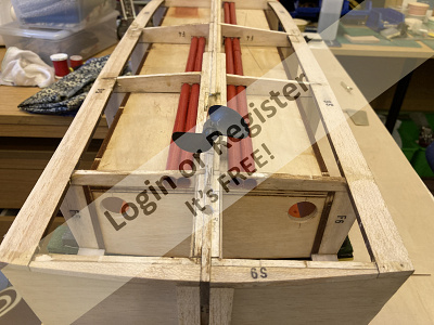
The bulkheads are made up from 4 parts and are glued in position according to the lines marked on the box and the keel, whilst preparing the individual pieces.
Removing the jointing bumps I started to think about the issue of hidden wiring under the box. On my crash tender I pre-drilled all the bulkheads with 10 mm holes the full length of the boat and then used a draw wire to pull wires through, however this is a different problem when finished you can’t get to the underside to pass wires through. My solution involved what some may say was a rather elaborate solution.
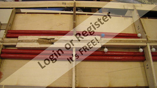
It involves some glue brown paper an 8mm rod and some varnish. The end objective was to make some “lightweight” tubes, I trawled the internet for large drinking straws but nothing fitted the bill, so on with the manufacture.
Taking some brown/red paper and a flat surface I rolled the paper around the tube in a spiral at the same time applying some glue then slid the resulting tube off the rod, I made several just to be sure I had enough.
The next process was to consolidate all the seams.This was done by laying each tube in a tray of water based varnish and hanging each one up to allow the excess to drain off back into the tray.
Next job was to put holes in the formers. I did this by pinning the port side pieces together and then boring a hole through all of them together using a home-made boring tool.
The tool is simply a piece of tube with cutting teeth filed into the end it doesn’t need to be HSS as balsa is so soft. I then pinned the starboard pieces together and bored through them but only from the stern to “F4” as only these carry the cables to the motor.
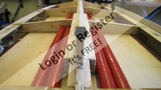
The assembly can now be done; adding the formers to the tubes and then gluing them to the box, making sure they are square to the box. Then finally adding the side pieces and bow bulkheads the whole assembly can now be set aside to dry.
A lengthy diversion but and enjoyable exercise and hopefully useful for feeding wires through now and maybe in the future.


Removing the jointing bumps I started to think about the issue of hidden wiring under the box. On my crash tender I pre-drilled all the bulkheads with 10 mm holes the full length of the boat and then used a draw wire to pull wires through, however this is a different problem when finished you can’t get to the underside to pass wires through. My solution involved what some may say was a rather elaborate solution.
It involves some glue brown paper an 8mm rod and some varnish. The end objective was to make some “lightweight” tubes, I trawled the internet for large drinking straws but nothing fitted the bill, so on with the manufacture.
Taking some brown/red paper and a flat surface I rolled the paper around the tube in a spiral at the same time applying some glue then slid the resulting tube off the rod, I made several just to be sure I had enough.
The next process was to consolidate all the seams.This was done by laying each tube in a tray of water based varnish and hanging each one up to allow the excess to drain off back into the tray.
Next job was to put holes in the formers. I did this by pinning the port side pieces together and then boring a hole through all of them together using a home-made boring tool.
The tool is simply a piece of tube with cutting teeth filed into the end it doesn’t need to be HSS as balsa is so soft. I then pinned the starboard pieces together and bored through them but only from the stern to “F4” as only these carry the cables to the motor.
The assembly can now be done; adding the formers to the tubes and then gluing them to the box, making sure they are square to the box. Then finally adding the side pieces and bow bulkheads the whole assembly can now be set aside to dry.
A lengthy diversion but and enjoyable exercise and hopefully useful for feeding wires through now and maybe in the future.
▲
⟩⟩
Ygagnon
figtree7nts
Joe727
MouldBuilder
stevedownunder
Colin H
marky
robbob
Martin555
|
💬 Re: Adding the bulkhead formers
4 years ago by 🇺🇸 figtree7nts (
Admiral)✧ 148 Views · 1 Like
Flag
Hi Michael,
That's very ingenious of you! Very well thought out! Cheers, Ed ▲
⟩⟩
Martin555
|
|
Login To
Remove Ads 💬 Re: Adding the bulkhead formers
4 years ago by 🇺🇸 Joe727 (
Commander)✧ 148 Views · 1 Like
Flag
Good of you to post the "paper tube" tip. I did this several times for scratch built models, just used cut up brown paper bags and white glue, works great and cheap like me.
Joe😎 ▲
⟩⟩
Martin555
|
|
💬 Re: Adding the bulkhead formers
4 years ago by 🇨🇦 Newby7 (
Fleet Admiral)✧ 148 Views · 1 Like
Flag
Well done and the only cost is time.
Rick ▲
⟩⟩
Martin555
|
|
💬 Re: Adding the bulkhead formers
4 years ago by 🇬🇧 Martin555 (
Fleet Admiral)✧ 148 Views · 0 Likes
Flag
I to find it challenging and interesting to be able to make something out of scraps/what ever i can find.
As everyone knows i just do not have a model making budget and if you have looked at some of my builds you can see that making things by hand for next to nothing can be very rewarding. So i for one will be watching to see what other deviations you come up with. Martin555. ▲
⟩⟩
No likes yet
This member will receive 1 point for every like received |
|
💬 Re: Adding the bulkhead formers
4 years ago by 🇬🇧 mturpin013 (
Admiral)✧ 148 Views · 1 Like
Flag
Its not as lightweight as paper and of course is very expensive, paper is cheap and for me its all about making a build interesting. There are many things in a build that you can buy but I like a challenge, building some of the available kits where everything comes on a "sprue" and is just glued together isn't for me, however for some its just right - "each to there own" as they say.
So expect some more diversions from the norm in this build. ▲
⟩⟩
Martin555
|
|
💬 Re: Adding the bulkhead formers
4 years ago by 🇬🇧 marky (
Commodore)✧ 148 Views · 1 Like
Flag
If you have a Home store + more near you they have big straws about 8mm diameter and 300mm long there are 20 in the pack for 79p.
Cheers Marky 👍 ▲
⟩⟩
Martin555
|
|
💬 Re: Adding the bulkhead formers
4 years ago by 🇬🇧 overthesea (
 Able Seaman) Able Seaman)✧ 151 Views · 1 Like
Flag
Instead of making yourself the tubes, why not use Plastic tubing such as Evergreen. It comes in many different sizes and of course is light in weight.😎
▲
⟩⟩
Martin555
|
|
💬 Re: Adding the bulkhead formers
4 years ago by 🇬🇧 mturpin013 (
Admiral)✧ 148 Views · 1 Like
Flag
I did consider metal tubes but didn't want to add weight
▲
⟩⟩
Martin555
|
|
💬 Re: Adding the bulkhead formers
4 years ago by 🇬🇧 mturpin013 (
Admiral)✧ 148 Views · 1 Like
Flag
OK, OK. Hand well slapped.
▲
⟩⟩
Martin555
|
|
💬 Re: Adding the bulkhead formers
4 years ago by 🇬🇧 Martin555 (
Fleet Admiral)✧ 148 Views · 1 Like
Flag
That is a very clever idea "Light weight conduit."
Excellent. Martin555. ▲
⟩⟩
stevedownunder
|
|
💬 Re: Adding the bulkhead formers
4 years ago by 🇩🇪 RNinMunich (
Fleet Admiral)✧ 148 Views · 2 Likes
Flag
An intricate and time consuming solution Mike.
If it works for you ....👍😉 During the 1st refit of my 1960s built 1/72 destroyer, and upgrading to RC ca 1986, I used 10mm alu tubes port and starboard to separate power and signal wires. Also offers a little extra screening from motor interference😊 Cheers, Doug 😎 ▲
⟩⟩
stevedownunder
Martin555
|
|
💬 Re: Adding the bulkhead formers
4 years ago by 🇬🇧 robbob (
Admiral)✧ 148 Views · 4 Likes
Flag
Good idea with the 'cardboard conduits' Mike!
Also....you'll be relieved that I'm not reviled by your revelation......😆 😂 Rob. ▲
⟩⟩
hmsnostalgia
Martin555
RNinMunich
stevedownunder
|
📝 Preparing and fitting the chines
4 years ago by 🇬🇧 mturpin013 ( Admiral)
Admiral)✧ 154 Views · 9 Likes · 2 Comments
Flag
💬 Add Comment
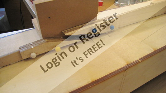
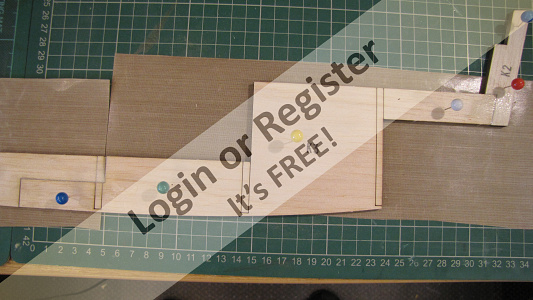
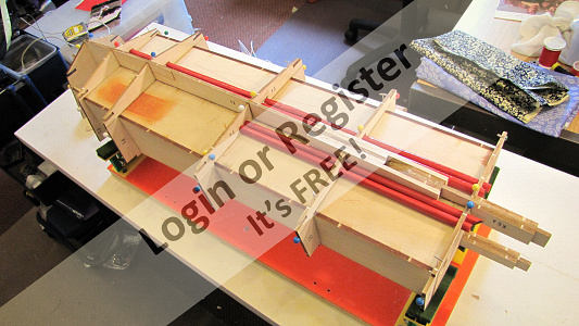
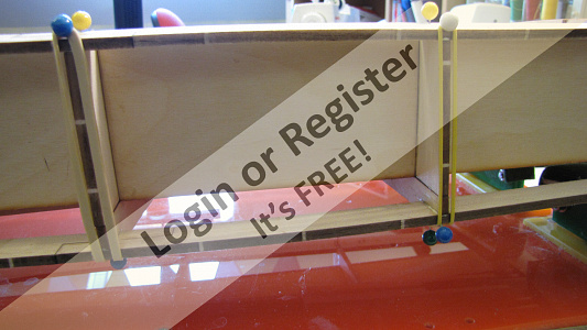
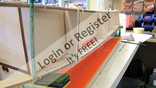
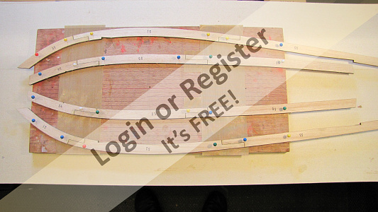
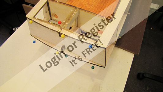
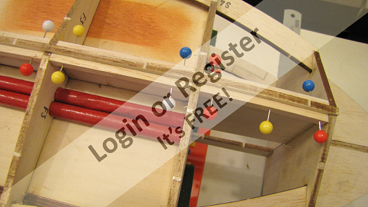
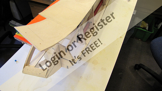
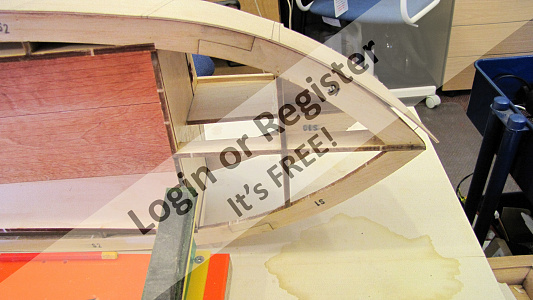
The chines are made from 3 pieces, which as with the keel, are very accurately laser cut, and can be laid on a flat surface with pieces of PTFE sheet under the joints and glued together with the aid of some pins to hold while the glue sets with confidence that they are the correct shape and will fit around the formers without any corrections.
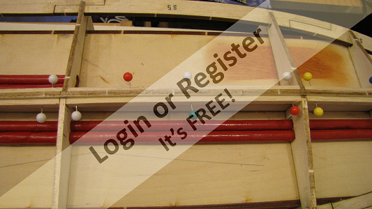
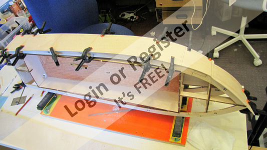
Now they are set they can be offered to the formers and secured in position, F1 needs some trimming to accommodate the curve but that’s all. I added the two lower chines first securing with aliphatic glue closely followed by the upper chine then I applied some securing pins top and bottom and quickly before the glue sets some elastic bands are applied to ensure some tension to the joints, the whole assembly was then left to dry.
Hopefully the pictures will show the detail better than a description.
▲
⟩⟩
MouldBuilder
Colin H
Ianh
Ygagnon
Martin555
stevedownunder
robbob
figtree7nts
RNinMunich
|
💬 Re: Preparing and fitting the chines
4 years ago by 🇿🇦 Ianh (
Commander)✧ 151 Views · 0 Likes
Flag
My 46' Crash tender is also very well cut and has no rectification work done as yet.👍👍👍
▲
⟩⟩
No likes yet
This member will receive 1 point for every like received |
|
💬 Re: Preparing and fitting the chines
4 years ago by 🇬🇧 robbob (
Admiral)✧ 151 Views · 2 Likes
Flag
Hi Mike.
Looks like VMW have refined the accuracy of the CNC and laser cutting even more since my build and it was pretty good even then ! There's probably little need to overlay the parts on the plan when glueing them together. I like the push pin and elastic band tensioners 👍 Rob. ▲
⟩⟩
hmsnostalgia
Martin555
|
📝 Adding small detail
4 years ago by 🇬🇧 mturpin013 ( Admiral)
Admiral)✧ 153 Views · 9 Likes · 4 Comments
Flag
💬 Add Comment
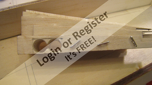
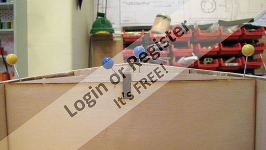
There are a number of small details that need to be added to give the curvature of the deck and also the curvature of the stern these are best described by pictures, as a long winded description will only cause confusion these will need trimming after the glue has set. In addition to these supplied pieces there needs to be some provision for strengthening the area where the exhaust exit at the stern as any pressure from the exhaust fitting could cause the stern ply to dent. These additional pieces were tapered to align with the curve of the stern and applied both internally and externally. To ensure everything lined up, the 8mm hole was first put into the balsa sub structure and the 4 inserts prepared, then I used a piece of PTFE coated oven sheet rolled up and placed through the 8mm balsa hole, then, adhesive applied the inserts were pushed over the rolled up oven sheet until they settled on the balsa sheet in the correct alignment.

▲
⟩⟩
Colin H
Skydive130
MouldBuilder
Ianh
Martin555
stevedownunder
RNinMunich
robbob
figtree7nts
|
💬 Re: Adding small detail
4 years ago by 🇭🇺 MouldBuilder (
Vice Admiral)✧ 151 Views · 1 Like
Flag
Looking good Mike. I am looking forward to playing with some wood soon😃
▲
⟩⟩
Martin555
|
|
Login To
Remove Ads 💬 Re: Adding small detail
4 years ago by 🇬🇧 Scratchbuilder (
Vice Admiral)✧ 151 Views · 1 Like
Flag
Starting to take shape Mike and will no doubt be to the same high standards as you other projects.
Bill 👍 ▲
⟩⟩
Martin555
|
|
💬 Re: Adding small detail
4 years ago by 🇨🇦 Newby7 (
Fleet Admiral)✧ 151 Views · 1 Like
Flag
I like the work you've done .Rick
▲
⟩⟩
Martin555
|
|
💬 Re: Adding small detail
4 years ago by 🇬🇧 robbob (
Admiral)✧ 151 Views · 3 Likes
Flag
Good progress Mike👍
Twin exhaust outlets eh...that should be interesting😉 Rob. ▲
⟩⟩
hmsnostalgia
Ianh
Martin555
|
📝 Rudder/water pick-up fittings
4 years ago by 🇬🇧 mturpin013 ( Admiral)
Admiral)✧ 153 Views · 6 Likes · 3 Comments
Flag
💬 Add Comment
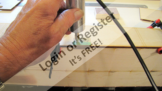
Whilst the construction is still in skeleton form I thought it better to put in the holes for the rudder and the water pick-ups in because at this stage it’s easier to hold the frame in a vice on my drilling machine. The holes are marked out and then the top K6/6a are held in a toolmakers clamp which is subsequently held in the vice so the holes can be drilled centrally and square with K7, both holes are drilled one 6mm (water scoop) & 8mm (rudder housing).
The rudder is a commercial item, loosely described as a “Large Rudder” which requires a small modification of turning the blade through 90 degrees and re drilling and riveting and then soft soldered just to make sure of a secure joint. The blade is then shortened by about 10mm on the trailing end and 5mm on the leading end, then a final polish and it’s ready for installation at a later stage.
The water scoop is a different issue, it’s one of those items that can be purchased for a few pounds but what’s the fun in that. I would much rather take the long route and make my own. I’ve documented this process before but here we go again. Using a piece of 0.250” brass tubing at 3” long the first job is to fill it with soft solder, tinman’s solder is best as it’s not as expensive as the cored solder, so resting one end on a piece of wood the tube is fluxed and then heated externally and the solder fed in from the top until its full to the top, its then left to cool. Holding the tube in the machine vice with a 50mm round bar in the jaw the tube can be easily drawn around the 50mm bar to the desired degree (about 35 degrees in this case). The tube is then held in the machine vice and trimmed to the appropriate shape on the inlet end. I then made a collar to be soldered on the tube in the appropriate place giving a position in line with the top of the propeller this will be epoxied in place at a later stage.
▲
⟩⟩
MouldBuilder
Colin H
Ianh
Skydive130
stevedownunder
neilmc
|
💬 Re: Rudder/water pick-up fittings
4 years ago by 🇨🇦 Newby7 (
Fleet Admiral)✧ 152 Views · 1 Like
Flag
I see you like building and soldering nice work Colin.
Rick ▲
⟩⟩
Martin555
|
|
Login To
Remove Ads 💬 Re: Rudder/water pick-up fittings
4 years ago by 🇬🇧 Skydive130 (
 Rear Admiral) Rear Admiral)✧ 152 Views · 1 Like
Flag
Nice simple explanation on how to make brass scoop, cheers Mike, will use that process on a future project 👍
▲
⟩⟩
Martin555
|
|
💬 Re: Rudder/water pick-up fittings
4 years ago by 🇬🇧 Martin555 (
Fleet Admiral)✧ 152 Views · 0 Likes
Flag
Nice work as usual Mike.
I like the fact that you like to make parts instead of buying them even if they are only a few pounds. Martin555. ▲
⟩⟩
No likes yet
This member will receive 1 point for every like received |
📝 Keel/skin support
4 years ago by 🇬🇧 mturpin013 ( Admiral)
Admiral)✧ 157 Views · 7 Likes
Flag
💬 Add Comment
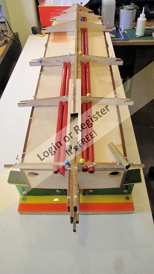
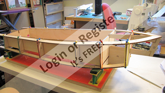
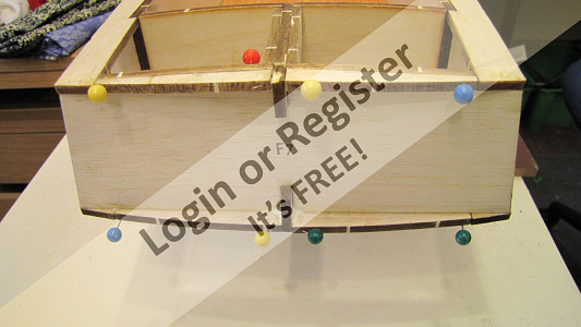
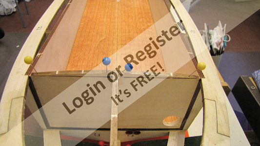
The bottom skin I think will need some additional support around the gaps between each of the lower formers so that the lower skin doesn’t sag between formers and is supported whist the adhesive is setting. I used some scrap pieces of balsa to fit the gaps making sure they were 1.5mm below the keel support.
The other preparatory thing I added was an additional block at the bow either side to use as reference points, the stern has two 12mm blocks which will also serve as reference point these will be used to position the skins when gluing.


The other preparatory thing I added was an additional block at the bow either side to use as reference points, the stern has two 12mm blocks which will also serve as reference point these will be used to position the skins when gluing.
▲
⟩⟩
MouldBuilder
Colin H
stevedownunder
Martin555
RNinMunich
robbob
Skydive130
📝 Fitting the side skins.
4 years ago by 🇬🇧 mturpin013 ( Admiral)
Admiral)✧ 161 Views · 11 Likes · 8 Comments
Flag
💬 Add Comment
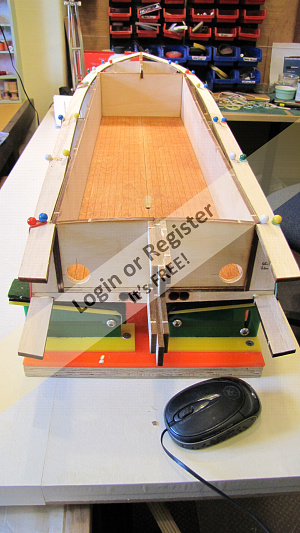
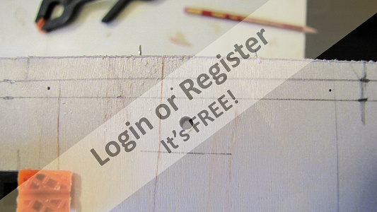
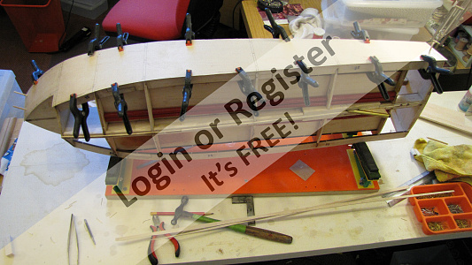
Fitting the skins is always an exciting part of the build for me as it starts to make the project start to look like a boat. the first job is to make sure the former's are “in line” by this I mean that the transition from one to another and on to the next doesn’t make the skin look as if you left something behind it and shows an undesirable bump in the profile. This is done with a piece of scrap flat wood with some say 120 grit abrasive glued flat to it, gently draw the block over the profile to remove any high spots, I sometimes mark the edges with a marker pen to show where the high spots are and in theory when a light rub remove or touches all areas you can assume the profile is ready for the skin.
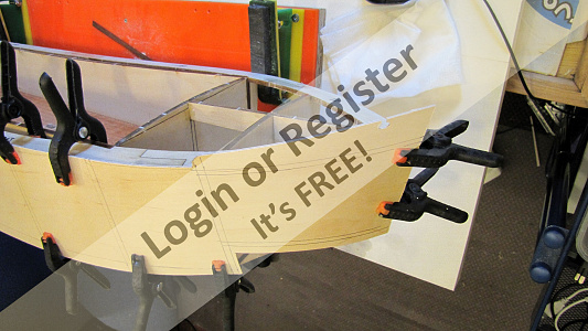
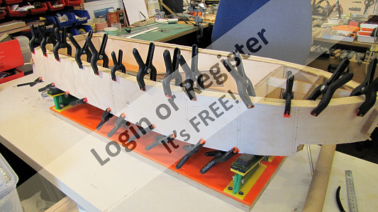
Skins are provided well over size and also will benefit from a little heat treatment on the bow. I like to trim as close as possible before gluing so a minimum of planning and sanding is required after. I first lay the skin over the frame and then and clamp along the length, then at the bow I applied some heat along with a light spray of water which quickly turns to steam but allows the ply to become pliable this is then bent around the bow and clamped, I now leave this overnight to dry and cool, which will hopefully retain the bend.
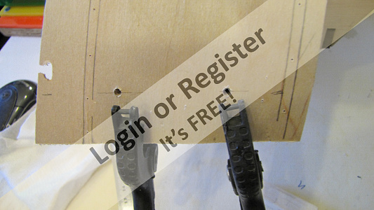
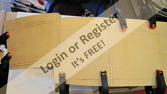
I then drill 2 x 3mm holes on the bow into the pre-prepared reference blocks to take a 3mm bamboo dowel; I then do the same at the stern. This is followed by scribing around the skin with a pencil to indicate the excess and also mark the position of the formers so holes can be drilled for pins to be driven into the formers exactly in the middle I then remove the clamps and dowels and remove the excess ply close to the pencil marks, and then drill some 0.4mm holes in the former positions for later pinning. Next I prepare some epoxy, the frame is then “glued up” ready for the application of the skin. Using the dowels the bow is located first, closely followed by the stern dowel; this locates the skin exactly ready for all the clamps to be applied, I then work along the marked positions of the formers and use some 0.5mm brass pins to ensure contact along the length of the formers, a final check that all the skin is in contact with the frame this is left to cure overnight.
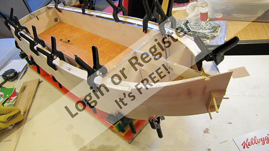
The other side is next but first some trimming at the bow is required so it doesn’t catch on the previously applied skin. I followed the same process on the second skin
The final operation on the side skins is to remove the excess ply, I prefer to use a jack plane for this job, which may sound OTT but I find its size an assistance in gauging the angle of the plane against the skins to get it level with the deck and the bottom chine, it’s also so easy to keep razor sharp and is easily adjustable to take minute cuts when required. It’s now ready for the bottom skins to be applied.

Skins are provided well over size and also will benefit from a little heat treatment on the bow. I like to trim as close as possible before gluing so a minimum of planning and sanding is required after. I first lay the skin over the frame and then and clamp along the length, then at the bow I applied some heat along with a light spray of water which quickly turns to steam but allows the ply to become pliable this is then bent around the bow and clamped, I now leave this overnight to dry and cool, which will hopefully retain the bend.
I then drill 2 x 3mm holes on the bow into the pre-prepared reference blocks to take a 3mm bamboo dowel; I then do the same at the stern. This is followed by scribing around the skin with a pencil to indicate the excess and also mark the position of the formers so holes can be drilled for pins to be driven into the formers exactly in the middle I then remove the clamps and dowels and remove the excess ply close to the pencil marks, and then drill some 0.4mm holes in the former positions for later pinning. Next I prepare some epoxy, the frame is then “glued up” ready for the application of the skin. Using the dowels the bow is located first, closely followed by the stern dowel; this locates the skin exactly ready for all the clamps to be applied, I then work along the marked positions of the formers and use some 0.5mm brass pins to ensure contact along the length of the formers, a final check that all the skin is in contact with the frame this is left to cure overnight.
The other side is next but first some trimming at the bow is required so it doesn’t catch on the previously applied skin. I followed the same process on the second skin
The final operation on the side skins is to remove the excess ply, I prefer to use a jack plane for this job, which may sound OTT but I find its size an assistance in gauging the angle of the plane against the skins to get it level with the deck and the bottom chine, it’s also so easy to keep razor sharp and is easily adjustable to take minute cuts when required. It’s now ready for the bottom skins to be applied.
▲
⟩⟩
MouldBuilder
Colin H
RNinMunich
jbkiwi
Martin555
Ianh
ChrisB
Jimbo1
stevedownunder
Skydive130
robbob
|
💬 Re: Fitting the side skins.
4 years ago by 🇩🇪 RNinMunich (
Fleet Admiral)✧ 159 Views · 2 Likes
Flag
Interesting!
Now the pics show properly, as I had reloaded them!? Site server must have untwisted it's knickers!😮 All's well ... 😁 😎 ▲
⟩⟩
robbob
Martin555
|
|
Login To
Remove Ads 💬 Re: Fitting the side skins.
4 years ago by 🇩🇪 RNinMunich (
Fleet Admiral)✧ 159 Views · 2 Likes
Flag
Hi Mike,
Re "Rob I tried to delete this pic but it won't disappear. its gone from the edit page but still appears in published area. " Normal editing didn't work for me either🤔 So I downloaded all except the fuzzy one, deleted all from your post. Then reloaded the pics one by one! All looked well. And then the damn thing reappeared when I looked through them on site. Sorry 😔 Something weird must have happened as you took/saved the photos and now it's confusing the way the site handles them! No idea how or why🤔 Odd thing is, the downloaded photos show perfectly on my PC using Irfan View!? Cheers, Doug 😎 ▲
⟩⟩
robbob
Martin555
|
|
💬 Re: Fitting the side skins.
4 years ago by 🇭🇺 MouldBuilder (
Vice Admiral)✧ 159 Views · 1 Like
Flag
So, that`s how you do it properly. It took me five years to fix the skins on my PTB.😁
▲
⟩⟩
RNinMunich
|
|
💬 Re: Fitting the side skins.
4 years ago by 🇬🇧 robbob (
Admiral)✧ 159 Views · 3 Likes
Flag
Must be the glue you're using 🤣.
Rob ▲
⟩⟩
Martin555
hmsnostalgia
Ianh
|
|
💬 Re: Fitting the side skins.
4 years ago by 🇬🇧 mturpin013 (
Admiral)✧ 159 Views · 2 Likes
Flag
Rob I tried to delete this pic but it won't disappear. its gone from the edit page but still appears in published area.
▲
⟩⟩
Ianh
robbob
|
|
💬 Re: Fitting the side skins.
4 years ago by 🇿🇦 Ianh (
Commander)✧ 159 Views · 1 Like
Flag
Never Enough Clamps!
▲
⟩⟩
Martin555
|
|
💬 Re: Fitting the side skins.
4 years ago by 🇬🇧 robbob (
Admiral)✧ 159 Views · 3 Likes
Flag
Very precise and methodical work Mike👍😀
I've found that just heating the ply skins with a heat gun (electric paint stripper) is sufficient to impart a permanent bend in ply skins without wetting or using steam. BTW. one of your 'photos is a bit fuzzy and I'm not sure what it's illustrating 🤔 Rob. ▲
⟩⟩
RNinMunich
hmsnostalgia
Martin555
|
|
💬 Re: Fitting the side skins.
4 years ago by 🇨🇦 Newby7 (
Fleet Admiral)✧ 160 Views · 2 Likes
Flag
Nice job looks good.
Rick ▲
⟩⟩
gordo
Martin555
|
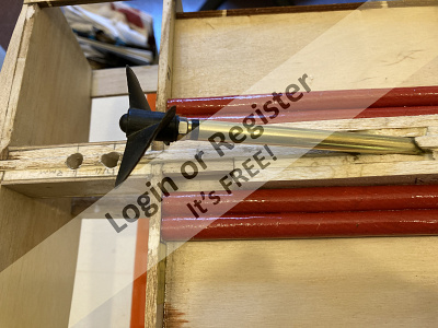
📝 Prop shaft(out of sequence)
4 years ago by 🇬🇧 mturpin013 ( Admiral)
Admiral)✧ 161 Views · 5 Likes
Flag
💬 Add Comment
I forgot to publish this operation at the correct build point so here it is slightly behind. The angle of the prop shaft is taken from the drawing so it can be transferred to the brass shaft whilst in situ; the hole created by the build leaves a square hole large enough to allow some vertical and lateral movement so I can now position the shaft with the aid of the angle gauge along the centre line and set using epoxy. The underwater part of the prop has a supporting ply quadrant which will be epoxied at the same time, I use some light wedges to position the shaft and hold it whilst the epoxy sets.


▲
⟩⟩
MouldBuilder
Colin H
Martin555
stevedownunder
Skydive130


Login To
Remove Ads
Remove Ads