Join Us On Social Media!

|

|

|
Download The App!
Login To
Remove Ads
Remove Ads
Login To
Remove Ads
Remove Ads
Model Boats Website
The VMW Marlin Cabin Cruiser by Robbob
31 Posts · 30 Followers · 319 Photos · 411 Likes
Began 11 months ago by
 United Kingdom
Follow This Thread
Not currently following
> Click to follow
> Click to follow
Latest Post 3 days ago by
| Most recent posts shown first (Show Oldest First) | (Print Booklet) |
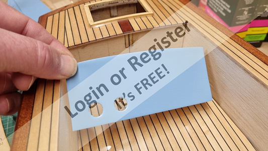
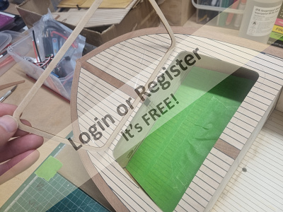
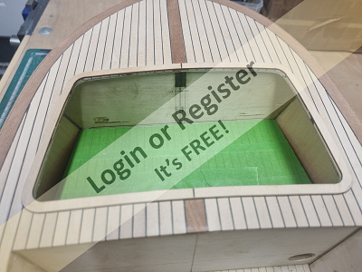
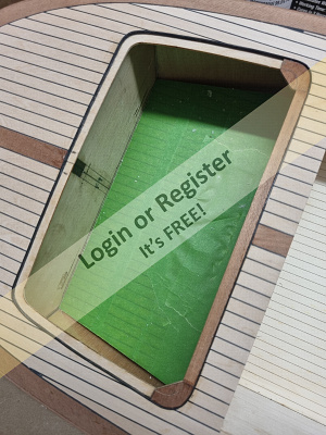
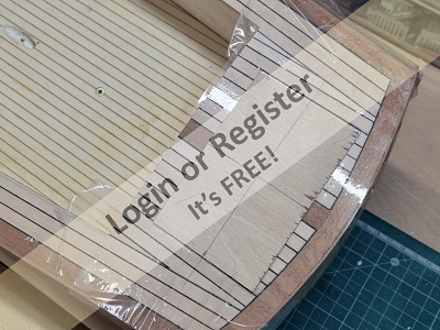
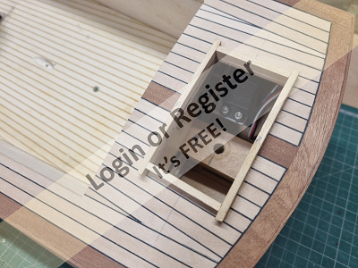
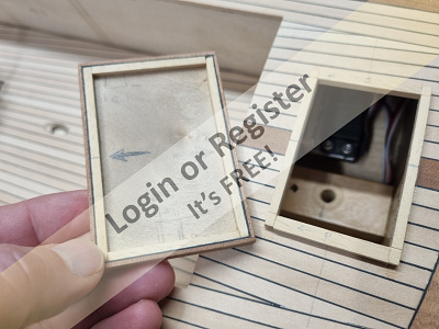
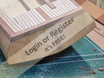
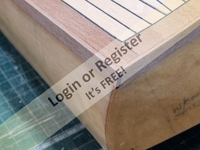
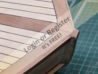
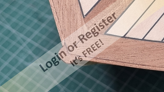
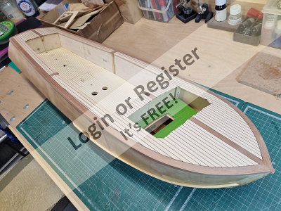
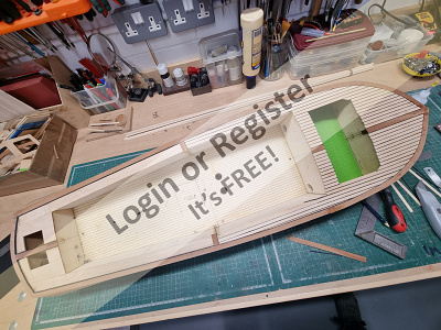
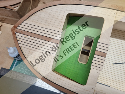
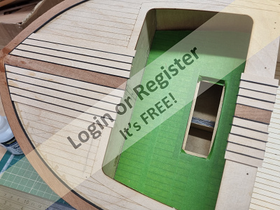
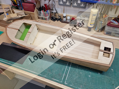
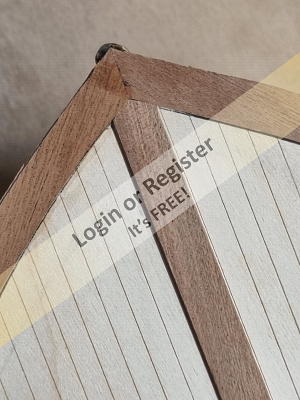
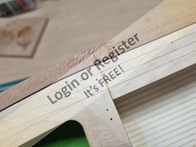
📝 Fitting the Well Deck Floor and Side Panels.
3 days ago by 🇬🇧 robbob ( Fleet Admiral)
Fleet Admiral)✧ 28 Views · 6 Likes · 1 Comment
Flag
💬 Add Comment
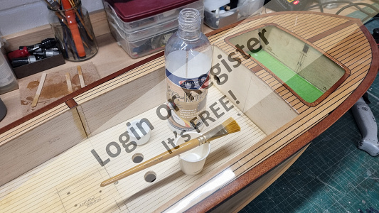
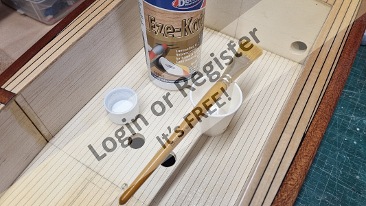
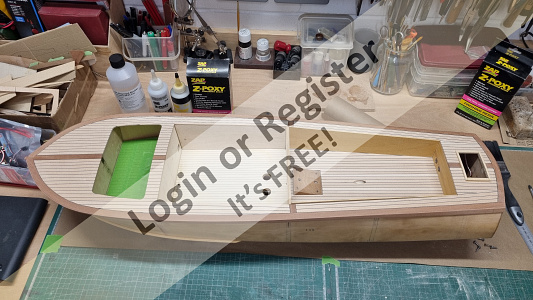
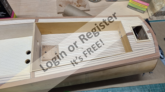
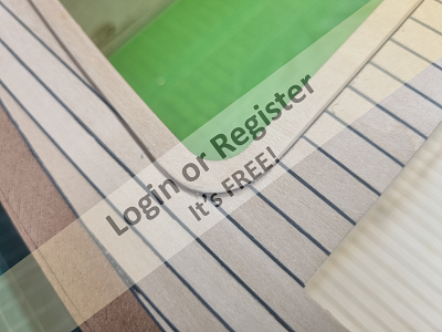
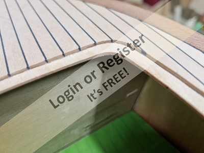
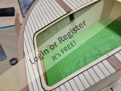
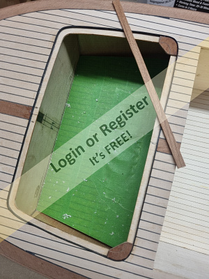
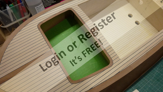
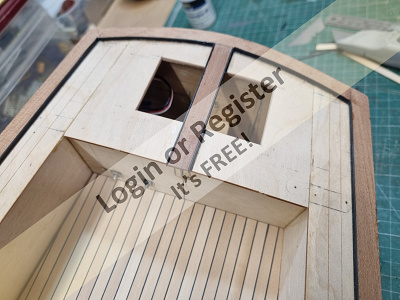
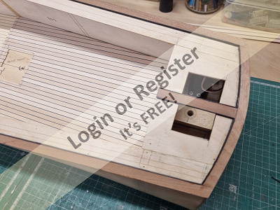
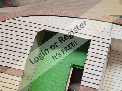
I finished the walls and floor area of what will be the cabin interior with several coats of Eze-Kote, which is a water-based finishing that dries very quickly and is very suited to sealing the woodgrain, but unlike sanding sealer, has no strong smell.
It makes for a very suitable surface for paint too after lightly rubbing down.
I'm undecided whether to paint the cabin interior as it will not really be seen as it will enclose the battery, power switch and R/C components etc.
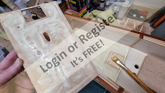
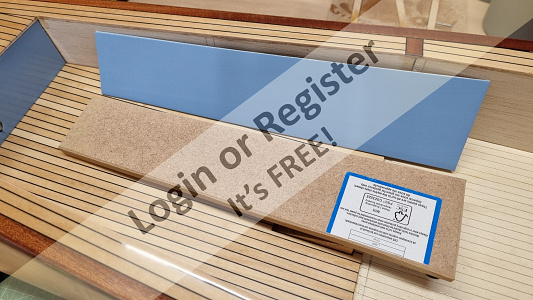
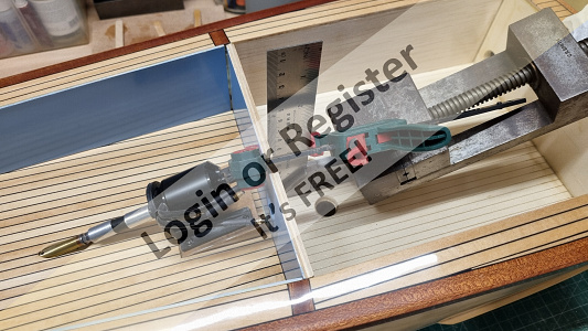
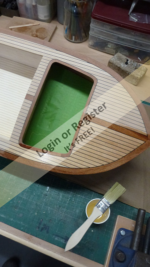
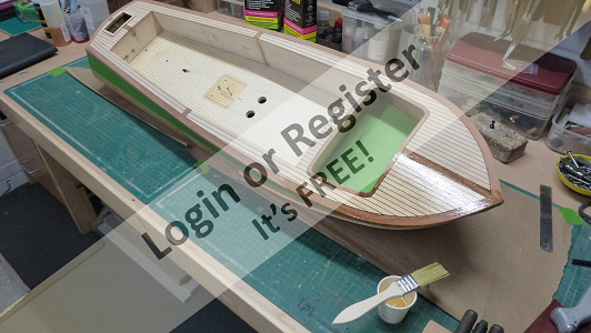
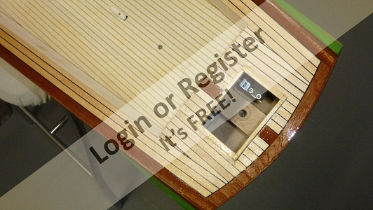
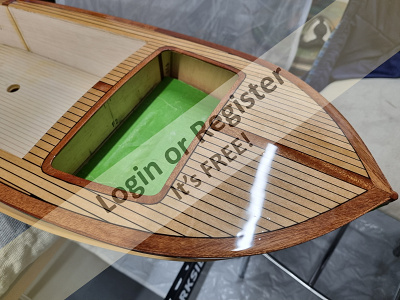
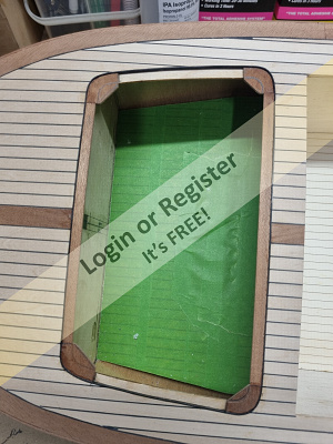
Meanwhile, the well deck floor panel now has a lovely high gloss epoxy finish and is ready to be glued down over the structural floor.
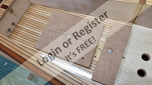
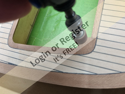
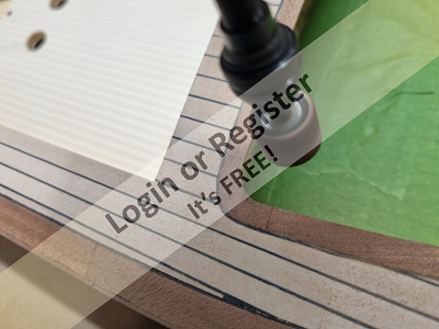
I used some aliphatic glue for this, spread evenly by brush on both surfaces and then clamped down using some MDF offcuts held down by some woodscrews through the motor mounting hole and the prop-shaft hole. This ensured that it would be bonded very well and be very flat.
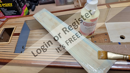
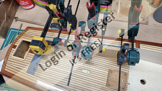
Once dried I could then fix the small painted panel to the wall at the end of the deck and then the two painted side panels. All were glued with aliphatic and clamped in place using some scrap MDF pieces to spread the load of the clamps and some soft cardboard to protect the painted surfaces.
It would be a shame to spoil them at this stage!
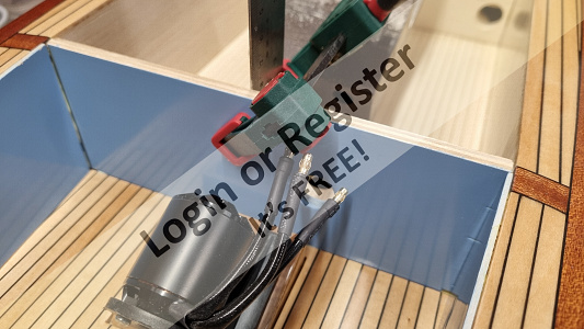
I can now consider doing the final alignment of the motor and prop-shaft using a rigid coupling and then fixing the shaft tube through the hull with epoxy resin.

It makes for a very suitable surface for paint too after lightly rubbing down.
I'm undecided whether to paint the cabin interior as it will not really be seen as it will enclose the battery, power switch and R/C components etc.
Meanwhile, the well deck floor panel now has a lovely high gloss epoxy finish and is ready to be glued down over the structural floor.
I used some aliphatic glue for this, spread evenly by brush on both surfaces and then clamped down using some MDF offcuts held down by some woodscrews through the motor mounting hole and the prop-shaft hole. This ensured that it would be bonded very well and be very flat.
Once dried I could then fix the small painted panel to the wall at the end of the deck and then the two painted side panels. All were glued with aliphatic and clamped in place using some scrap MDF pieces to spread the load of the clamps and some soft cardboard to protect the painted surfaces.
It would be a shame to spoil them at this stage!
I can now consider doing the final alignment of the motor and prop-shaft using a rigid coupling and then fixing the shaft tube through the hull with epoxy resin.
▲
⟩⟩
Rookysailor
Chum444
PhilH
Missouri
DWBrinkman
chugalone100
|
💬 Re: Fitting the Well Deck Floor and Side Panels.
3 days ago by 🇬🇧 Missouri (
 Master Seaman) Master Seaman)✧ 25 Views · 1 Like
Flag
You might want to use a few more clamps just to be sure.
▲
⟩⟩
robbob
|
Login To
Remove Ads
Remove Ads
📝 Painting the Well Deck.
23 days ago by 🇬🇧 robbob ( Fleet Admiral)
Fleet Admiral)✧ 40 Views · 10 Likes · 2 Comments
Flag
💬 Add Comment
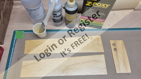
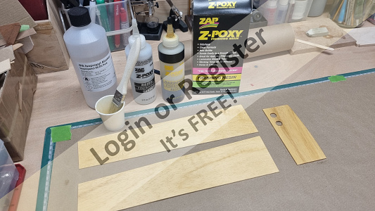
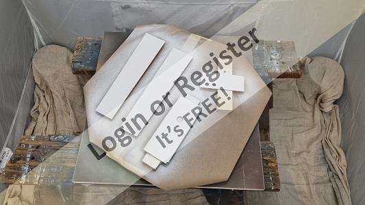
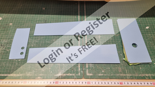
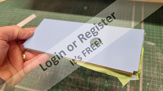
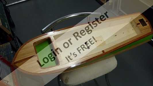
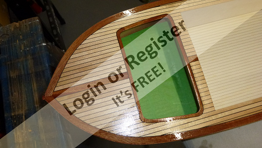
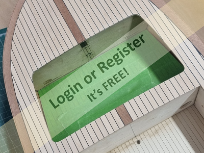
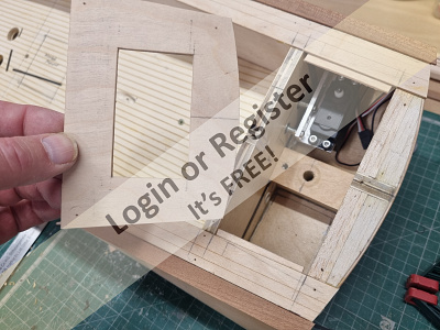
I want the walls of the well deck to have a nice pastel blue colour but spraying the area directly will prove to be difficult and the resulting finish may not be very good.
The solution, I decided, was to make some separate panels from some 1.5mm obeche sheets which will act as liners that I could easily paint and finish and then glue in place.
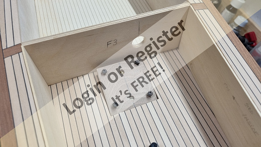
The panels were easy to make to be a good close fit and included a panel for the rear wall of the well deck, with some clearance holes for the servo mount screws and also the bulkhead F3, which I have re-made in ply for strength, which I had yet to fix in place.
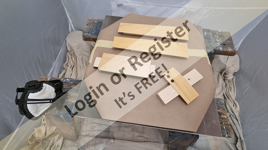
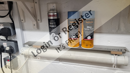
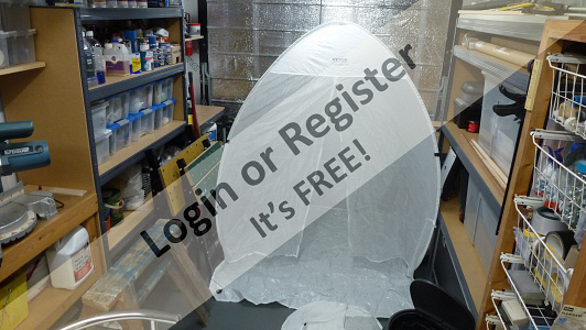
Once I was satisfied with the fit I applied some Z-Poxy resin in several coats to obtain a smooth finish and then all four parts were put into my recently acquired spray tent and given some light coats of white primer.
After a light rub down with fine abrasive and cleaned with some panel wipe I applied two coats of some Halfords acrylic gloss in a light pastel blue colour.
My painting process not only includes preparing the surface for the best finish but also warming the paint first which I do on a ‘shelf’ above a tubular heater and then a thorough mixing by shaking the can as recommended.
I will glue these panels and the F3 bulkhead in place after I have glued down the well deck floor.


The solution, I decided, was to make some separate panels from some 1.5mm obeche sheets which will act as liners that I could easily paint and finish and then glue in place.
The panels were easy to make to be a good close fit and included a panel for the rear wall of the well deck, with some clearance holes for the servo mount screws and also the bulkhead F3, which I have re-made in ply for strength, which I had yet to fix in place.
Once I was satisfied with the fit I applied some Z-Poxy resin in several coats to obtain a smooth finish and then all four parts were put into my recently acquired spray tent and given some light coats of white primer.
After a light rub down with fine abrasive and cleaned with some panel wipe I applied two coats of some Halfords acrylic gloss in a light pastel blue colour.
My painting process not only includes preparing the surface for the best finish but also warming the paint first which I do on a ‘shelf’ above a tubular heater and then a thorough mixing by shaking the can as recommended.
I will glue these panels and the F3 bulkhead in place after I have glued down the well deck floor.
▲
⟩⟩
BOATSHED
DWBrinkman
EdW
chugalone100
TonyAsh
PhilH
Missouri
roycv
Rookysailor
pressonreguardless
|
💬 Re: Painting the Well Deck.
22 days ago by 🇬🇧 robbob (
Fleet Admiral)✧ 35 Views · 0 Likes
Flag
Hi Phil.
The sET (sprayEjecting Tent), came from planet YaBe and materialised on my doorstep from a big red mothership that accelerated away at unearthly speed, and very nearly ran over my neighbours cat. 🤣 ▲
⟩⟩
No likes yet
This member will receive 1 point for every like received |
|
💬 Re: Painting the Well Deck.
22 days ago by 🇬🇧 PhilH (
 Lieutenant Commander) Lieutenant Commander)✧ 38 Views · 1 Like
Flag
I thought that you had been visited trom those little green men for a minute when i saw that white thing in your workshop😜 but good idea not seen one before looke like a good setup you have there.
Philuk👍 ▲
⟩⟩
robbob
|
📝 Finishing the Decks with Epoxy Resin.
1 month ago by 🇬🇧 robbob ( Fleet Admiral)
Fleet Admiral)✧ 56 Views · 13 Likes · 5 Comments
Flag
💬 Add Comment
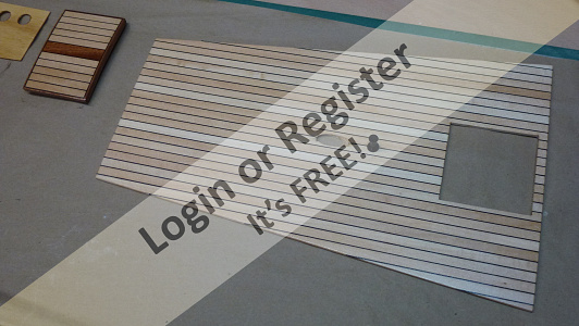
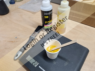
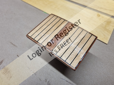
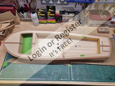
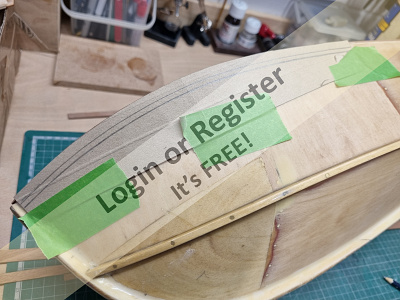
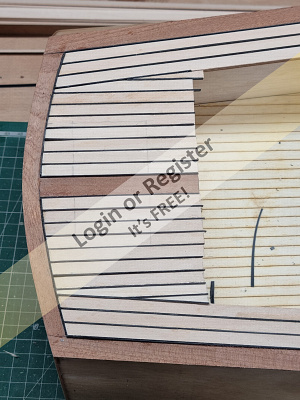
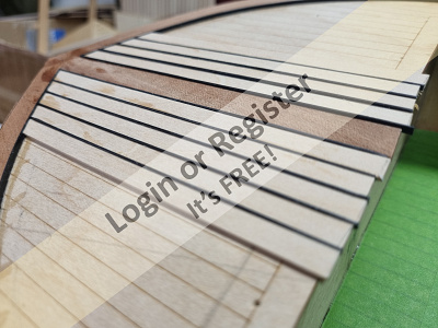
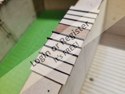
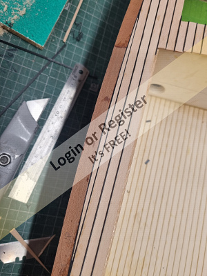
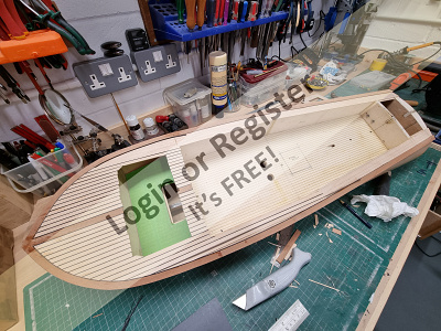
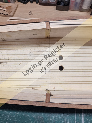
All the planking is now complete and ready for the several coats of epoxy finishing resin to achieve the final finish that I want.
I had previously planked and finished the forward well deck floor, which is currently covered in green masking tape to protect it, and I noted that the first coat of resin really could have been thinned to let the limewood and mahogany strips take up the finish more readily.
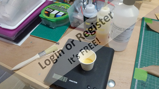
With this in mind, and after a bit of research on the matter, I decided that I would dilute the initial coat of resin on the remaining planking with some isopropyl alcohol that I had ordered over the internet.
It’s important to use the very purest alcohol with the lowest water content to be most effective and I had also read that the resin and catalyst ratio should still be 50:50 by weight but with the maximum addition of 25% isopropyl alcohol. Any more than this could retard the curing and hardening of the resin.
The alcohol I use is 99.9% pure and the resultant epoxy mix soaks into the porous wood much better rather than laying on the surface and still cures and hardens in the same amount of time.
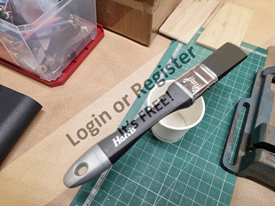
The first piece I coated to test the new resin finishing process was the separate planked panel that is the large well deck floor, and after curing and hardening I rubbed this down with some abrasive and then applied two further undiluted coats of resin rubbed down between coats.
I used cheap disposable brushes to apply the initial coats of resin, the occasional stray brush hair is easily removed but for the final coat I used a much better quality brush. The final coat was then rubbed down with progressively finer grades of wet & dry abrasive paper and then polished with a liquid abrasive (T-Cut) to reveal a very high gloss finish.
Confident that I could achieve the depth of finish I wanted on all of the planking I masked all around the hull gunwale strips and then applied the first thinned coats and subsequent un-thinned coats to the main deck and the hatch cover.
I had previously planked and finished the forward well deck floor, which is currently covered in green masking tape to protect it, and I noted that the first coat of resin really could have been thinned to let the limewood and mahogany strips take up the finish more readily.
With this in mind, and after a bit of research on the matter, I decided that I would dilute the initial coat of resin on the remaining planking with some isopropyl alcohol that I had ordered over the internet.
It’s important to use the very purest alcohol with the lowest water content to be most effective and I had also read that the resin and catalyst ratio should still be 50:50 by weight but with the maximum addition of 25% isopropyl alcohol. Any more than this could retard the curing and hardening of the resin.
The alcohol I use is 99.9% pure and the resultant epoxy mix soaks into the porous wood much better rather than laying on the surface and still cures and hardens in the same amount of time.
The first piece I coated to test the new resin finishing process was the separate planked panel that is the large well deck floor, and after curing and hardening I rubbed this down with some abrasive and then applied two further undiluted coats of resin rubbed down between coats.
I used cheap disposable brushes to apply the initial coats of resin, the occasional stray brush hair is easily removed but for the final coat I used a much better quality brush. The final coat was then rubbed down with progressively finer grades of wet & dry abrasive paper and then polished with a liquid abrasive (T-Cut) to reveal a very high gloss finish.
Confident that I could achieve the depth of finish I wanted on all of the planking I masked all around the hull gunwale strips and then applied the first thinned coats and subsequent un-thinned coats to the main deck and the hatch cover.
▲
⟩⟩
DWBrinkman
pressonreguardless
premecekcz
Mike Stoney
Jay
Heners2332
EdW
Rookysailor
Missouri
Chum444
hermank
ChrisF
chugalone100
|
💬 Re: Finishing the Decks with Epoxy Resin.
1 month ago by 🇨🇭 IGinBasel (
Master Seaman)✧ 50 Views · 2 Likes
Flag
Perseverance and elbow grease . . . Fantastic!
I am contemplating the VMW 46" crash tender, solely due to your fabulous build logs (in spite of the missing flare in the bow). Ian pic: Bluejacket Maine Lobster Boat (considerably reworked) 
▲
⟩⟩
DWBrinkman
robbob
|
|
Login To
Remove Ads 💬 Re: Finishing the Decks with Epoxy Resin.
1 month ago by 🇬🇧 Rookysailor (
 Rear Admiral) Rear Admiral)✧ 52 Views · 1 Like
Flag
Much appreciated for that info Rob, have never used the Z-poxy resin before, so your information is most welome.
Cheers, Pete😊 ▲
⟩⟩
hermank
|
|
💬 Re: Finishing the Decks with Epoxy Resin.
1 month ago by 🇬🇧 robbob (
Fleet Admiral)✧ 52 Views · 4 Likes
Flag
Hi Pete.
The product description says a pot life of 20-30 minutes, hardening after 3 hours and is sandable after 6 hours. In practice I have found it hardened in 2 hours and I'm able to sand it after 5 hours but if there's no rush I much prefer to leave it overnight before any sanding and re-coating. The addition of 25% IPA in the first coat seems to harden and cure in much the same time with no ill effect. Previously I was using 'Easy Composites' cloth, resin & hardener but that always had a very extended hardening and curing time that made the process so much more time consuming. And despite cleaning surfaces with panel wipe, which I also still do with the Z-Poxy resin, I would often find 'fish eyes' in the finish that were always difficult to rectify after curing. Thankfully this never occurs with Z-Pozy finishing resin. ▲
⟩⟩
Missouri
hermank
Rookysailor
Jay
|
|
💬 Re: Finishing the Decks with Epoxy Resin.
1 month ago by 🇬🇧 Rookysailor (
Rear Admiral)✧ 57 Views · 2 Likes
Flag
How long does it take for the resin to go off Rob? and how much longer with the addition of the IPA?
Beautiful finish btw. Cheers, Pete😊 ▲
⟩⟩
Heners2332
hermank
|
|
💬 Re: Finishing the Decks with Epoxy Resin.
1 month ago by 🇺🇸 chugalone100 (
 Captain) Captain)✧ 60 Views · 2 Likes
Flag
That is one super sharp looking deck.
Great work. 😎 ▲
⟩⟩
robbob
hermank
|
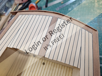
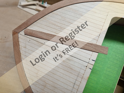
📝 The Forward Deck, Adding More Detail.
2 months ago by 🇬🇧 robbob ( Fleet Admiral)
Fleet Admiral)✧ 63 Views · 10 Likes · 3 Comments
Flag
💬 Add Comment
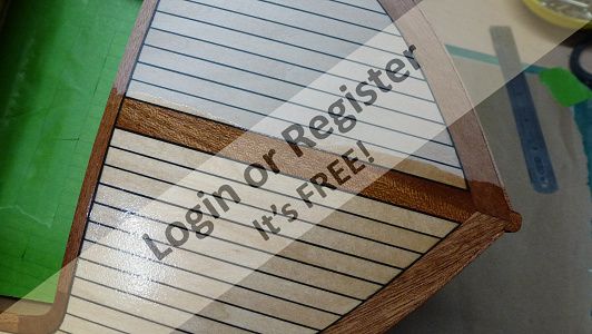
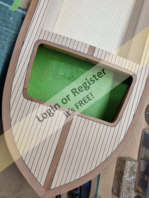
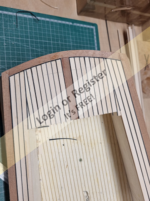
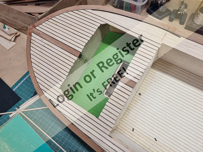
When I planked the forward part of the deck around the passenger well I brought the planking right up to the edges of the hole, and on reflection this could have really done with a mahogany border to better define it.
In part the border will be concealed by the main cabin front screen and the small screen in front of the passenger well but I decided that it would be worth trying to cut away the planking and fit a border to improve the detailing of the forward deck.
Fortunately, I kept the ply sheet that the deck panels were laser cut from and was able to use that to make a template of the border to the width that I wanted that included a margin for some black plasticard caulking.
I used this to mark a cutting line around the hole and the proceeded to, with extreme care! cut through the planking with a very new and very sharp blade in my craft knife.
The corner radiuses were particularly tricky and I only had one very minor knife slippage which I’m hoping I can sand off. I actually slightly undercut the planking to ensure that the caulking strips would fit without any gapping.
This worked very well and I could then cut and apply the plasticard strips to the planking edges. The corners of the boarder were made from individual pieces of mahogany sheet trimmed to fit each corner tightly and then I applied some mahogany strips to join it all up.
The internal corners were then sanded back to an even width using a sanding drum in my Deremel tool.
I finished by sanding back the area to blend in the caulking and border strips around the passenger well. The process went better than expected and I think it will look really good once finished in clear high gloss epoxy resin.
▲
⟩⟩
pressonreguardless
Heners2332
Missouri
ChrisF
EdW
Rookysailor
Chum444
hermank
HappyHaggis
Jay
|
💬 Re: The Forward Deck, Adding More Detail.
2 months ago by 🇬🇧 ChrisF (
 Vice Admiral) Vice Admiral)✧ 64 Views · 1 Like
Flag
You definitely made the right decision there, it looks just the job, some fine precision work.
Chris ▲
⟩⟩
hermank
|
|
Login To
Remove Ads 💬 Re: The Forward Deck, Adding More Detail.
2 months ago by 🇺🇸 Chum444 (
 Commodore) Commodore)✧ 66 Views · 1 Like
Flag
Excellent precise work.👍
▲
⟩⟩
hermank
|
|
💬 Re: The Forward Deck, Adding More Detail.
2 months ago by 🇬🇧 HappyHaggis (
 Sub-Lieutenant) Sub-Lieutenant)✧ 68 Views · 2 Likes
Flag
Extreme care has paid off. Just look how perfect she is ❤️
▲
⟩⟩
hermank
robbob
|
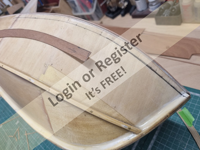
📝 Making the Rear Hatch
2 months ago by 🇬🇧 robbob ( Fleet Admiral)
Fleet Admiral)✧ 74 Views · 13 Likes · 2 Comments
Flag
💬 Add Comment
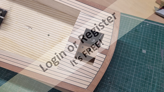
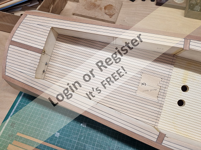
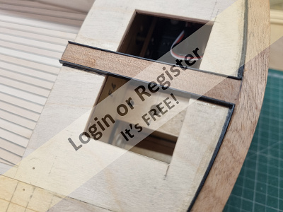
When I planked the rear deck area, I deliberately covered over the hole that I had made previously for the servo and rudder access hatch just to make application of the planking quicker and easier.
This now needs to be cut out to reveal the hole so that I can form a proper hatch which was easily done using a Dremel routing bit and finishing with sharp craft knife and files.
I applied several strips of clear packing tape over the rear deck to protect the newly planked surface and cut an oversize piece of 1.5mm ply for the hatch cover.
As I want this cover to have the same curvature as the deck itself, I heated and bent the piece to the same curve as the rear deck and I applied the planking and plasticard ‘caulking’ to this panel whilst it was curved.
I formed the coaming around the deck aperture from some obeche strips, making several shallow cuts using a razor saw to help them bend, to ensure that they also followed the deck curvature. I then formed a corresponding frame on the underside of the planked panel so that it mated with the deck coaming without too tight a fit to allow for surface finishing.
The planking was then trimmed off around the panel and some ‘caulking’ and mahogany border strips fitted around it to complete the hatch cover. The caulking was trimmed back and the hatch given a thorough sanding in readiness for finishing.
Later I will be fitting some small neodymium magnets in the coaming and the hatch cover to secure the hatch firmly in place.
▲
⟩⟩
jbkiwi
EdW
Rookysailor
Chum444
Missouri
DWBrinkman
Jay
roycv
pressonreguardless
hermank
chugalone100
RNinMunich
Ronald
|
💬 Re: Making the Rear Hatch
2 months ago by 🇺🇸 chugalone100 (
Captain)✧ 73 Views · 5 Likes
Flag
Looking great, Robbob.
It’s always tricky to design a hatch that’s secure enough to withstand the wake generated by other models. I used six 5 mm magnets, with a piece of galvanized steel on the hatch, and I’m hoping this setup will perform as well as yours. 
▲
⟩⟩
HappyHaggis
EdW
DWBrinkman
pressonreguardless
hermank
|
|
💬 Re: Making the Rear Hatch
2 months ago by 🇨🇦 Ronald (
Fleet Admiral)✧ 78 Views · 2 Likes
Flag
Nice neat niffty nimble masterpiece
▲
⟩⟩
HappyHaggis
hermank
|
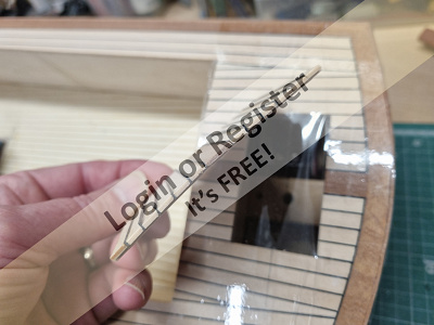
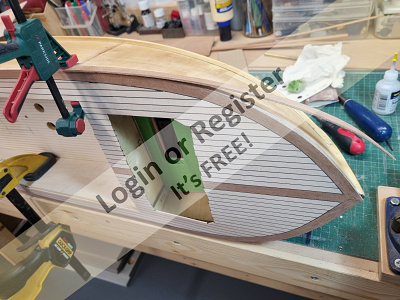
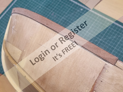
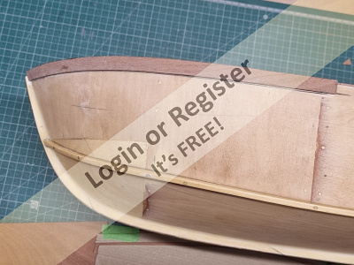
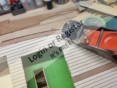
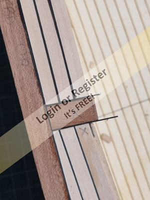
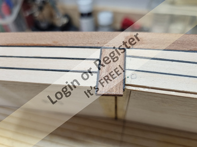
📝 Fitting a Mahogany Gunwale.
2 months ago by 🇬🇧 robbob ( Fleet Admiral)
Fleet Admiral)✧ 88 Views · 11 Likes · 4 Comments
Flag
💬 Add Comment
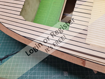
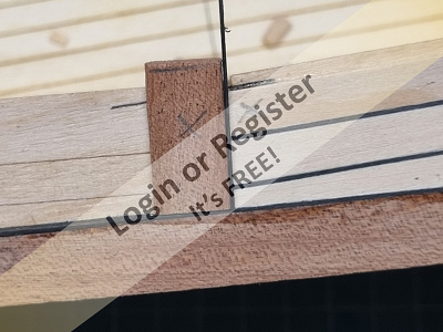
Now that the whole deck is planked I can fit a mahogany gunwale around the hull which will be a good edge for the hull paint finish as well as a nice finishing detail.
I can’t use a plain and straight strip of mahogany for this, as to accommodate the curvature of the bow the strip would have to be contorted in two planes which is not possible to do.
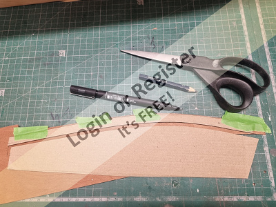
The solution was to use some thin card taped around the bow to form a template of suitable width and length that could be transferred to some mahogany sheet.
This was very carefully cut from a sheet of 1.6mm mahogany allowing for a small overlap on the upper edge for later trimming and a finished width of 9mm which looked to be in proportion.
A test fit proved that the strip conformed extremely well to the compound curvature and I then wetted, steamed and bent both pieces so that they fitted closely to the curve.
These bow pieces only need to go far enough around the hull to a point where a regular strip of mahogany can be used to extend the gunwale to the stern. The bow pieces were fixed in place with some five-minute epoxy resin and held in place with clamps and some tape until set.
I then continued the gunwale with some strip mahogany to the stern with a similar overlap for later trimming.
The stern piece required the making of a similar card template and a piece was cut from the mahogany sheet and fixed with some epoxy.
Once glued and set I trimmed back the overlap of this gunwale strip all around the hull with my trusty ‘Record’ hand plane.
At the bow I added a small piece of mahogany to cover the top of the keel piece where it meets the deck.
I then gave the entire deck a thorough sanding using progressively finer grades of abrasive paper until I obtained a satisfactory surface for finishing.

I can’t use a plain and straight strip of mahogany for this, as to accommodate the curvature of the bow the strip would have to be contorted in two planes which is not possible to do.
The solution was to use some thin card taped around the bow to form a template of suitable width and length that could be transferred to some mahogany sheet.
This was very carefully cut from a sheet of 1.6mm mahogany allowing for a small overlap on the upper edge for later trimming and a finished width of 9mm which looked to be in proportion.
A test fit proved that the strip conformed extremely well to the compound curvature and I then wetted, steamed and bent both pieces so that they fitted closely to the curve.
These bow pieces only need to go far enough around the hull to a point where a regular strip of mahogany can be used to extend the gunwale to the stern. The bow pieces were fixed in place with some five-minute epoxy resin and held in place with clamps and some tape until set.
I then continued the gunwale with some strip mahogany to the stern with a similar overlap for later trimming.
The stern piece required the making of a similar card template and a piece was cut from the mahogany sheet and fixed with some epoxy.
Once glued and set I trimmed back the overlap of this gunwale strip all around the hull with my trusty ‘Record’ hand plane.
At the bow I added a small piece of mahogany to cover the top of the keel piece where it meets the deck.
I then gave the entire deck a thorough sanding using progressively finer grades of abrasive paper until I obtained a satisfactory surface for finishing.
▲
⟩⟩
EdW
Jay
RossM
RNinMunich
Missouri
Ronald
Rookysailor
hermank
pressonreguardless
chugalone100
roycv
|
💬 Re: Fitting a Mahogany Gunwale.
2 months ago by 🇬🇧 robbob (
Fleet Admiral)✧ 83 Views · 3 Likes
Flag
Hi Ronald.
"Are you using veneer?" No it's not veneer which is usually very much thinner than the 1.5mm limewood planks and 1.6mm mahogany strip that I'm using. The final finish will be several coats of Z-Poxy Finishing Resin which certainly does bring out the grain and colour of the wood😎. Rob. ▲
⟩⟩
Missouri
Jay
Ronald
|
|
Login To
Remove Ads 💬 Re: Fitting a Mahogany Gunwale.
2 months ago by 🇬🇧 PhilH (
Lieutenant Commander)✧ 86 Views · 1 Like
Flag
There are some great finishes on your boat you have done a very nice job it i love the two colours should look very smart
Philuk👍 ▲
⟩⟩
hermank
|
|
💬 Re: Fitting a Mahogany Gunwale.
2 months ago by 🇨🇦 Ronald (
Fleet Admiral)✧ 92 Views · 1 Like
Flag
Superb!
Are you using veneer? ▲
⟩⟩
hermank
|
|
💬 Re: Fitting a Mahogany Gunwale.
2 months ago by 🇺🇸 chugalone100 (
Captain)✧ 90 Views · 1 Like
Flag
Robbob:
Absolutely magnificent! Once that model is finished, the rich mahogany color will really come alive and make the whole piece stand out beautifully. 😎 ▲
⟩⟩
hermank
|
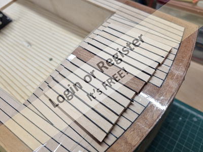
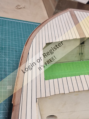
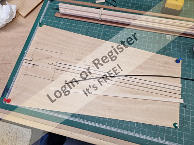
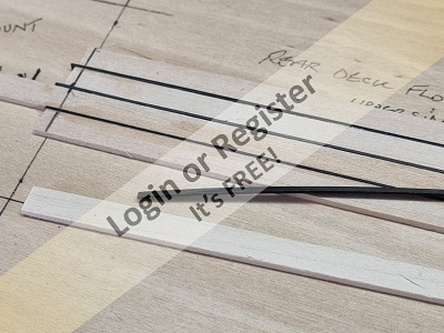
📝 Planking the Deck. Part 3.
2 months ago by 🇬🇧 robbob ( Fleet Admiral)
Fleet Admiral)✧ 92 Views · 9 Likes
Flag
💬 Add Comment
Happy New Year to everybody, I hope you all had a fun but relaxing time over the festive period! 😀
Now...onwards with the VMW Marlin kit that's taken far too long to get its current state 😮.
I continued with the planking on the side decks from the transition point and then started on the rear deck, the process is really quite quick and easy once you get into a rhythm and the lime planking is very easy to work with. I ordered more than enough of this from the supplier (SLEC) to easily cover the required areas with enough in reserve for any future decking needs too. The mahogany sheets for the contrasting detail came from the same source.
For the rear deck I decided to apply the planking over the hatch aperture rather than fit fiddly little pieces on either side of it with a view to opening up the hatch afterwards.
The angle transition of the side decks looks, in my view, pretty good and was certainly a better way to continue the planking along the sides.
I took a very sharp chisel to the entire deck area to pare back the black plasticard ‘caulking’ lines.
I’ll give the decks a final trim around the lower deck areas where they overlap the edges and then give the whole deck a thorough sanding later on, but the next job will be to form some mahogany strips to use around the deck on the sides of the hull, these will make a nice gunwale feature and also become a good clean edge for the hull paint finish too.
Very soon I'll need to decide on a suitable colour scheme, perhaps a pale blue or green with white or cream on the hull?
A visit to Halfords (Automotive parts and paints supplier in the UK) may be in order to see what acrylic colours are available!
▲
⟩⟩
Jay
hermank
pressonreguardless
tonyb2
Chum444
Rookysailor
Missouri
roycv
Mike W
📝 Planking the deck. Part 2.
3 months ago by 🇬🇧 robbob ( Fleet Admiral)
Fleet Admiral)✧ 98 Views · 12 Likes · 1 Comment
Flag
💬 Add Comment
After fitting all of the mahogany border strips to the deck I cut lots of strips of .5mm black plasticard and added them to the inside faces of the mahogany all around the deck and also the central mahogany detail strip.
At this stage I decided to add the last piece of ply deck at the stern, this was cut from fresh 1.5mm ply and the hatch opening formed.
This was glued down, and when set I made a card template of the stern deck, and produced the mahogany edging for this and stuck that down too. The black plasticard ‘caulking’ was added to this as well.
I then started adding the limewood planks and caulking to the front deck working outwards from the centre mahogany strip, the very outer strips continue down the deck sides, some of which a quite narrow, and these required very careful shaping to fit without any gaps which would spoil the look.
These outer strips only extend half way down the deck as I decided to introduce another mahogany strip as a transition point for the planking so that the remaining strips would be parallel to the well deck sides. I felt that this would look far better than to continue the side planking in ever narrowing strips up to the rear deck.
▲
⟩⟩
Jay
pressonreguardless
tonyb2
Mike W
ChrisF
hermank
RossM
RNinMunich
Ronald
Missouri
Rookysailor
Madwelshman
|
💬 Re: Planking the deck. Part 2.
3 months ago by 🇨🇦 Ronald (
Fleet Admiral)✧ 103 Views · 3 Likes
Flag
Nicely done!
▲
⟩⟩
Mike W
robbob
hermank
|
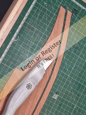
📝 Planking the deck. Part 1.
3 months ago by 🇬🇧 robbob ( Fleet Admiral)
Fleet Admiral)✧ 107 Views · 19 Likes · 5 Comments
Flag
💬 Add Comment
The planking of the lower rear deck seemed to go quite well but the main deck will be a bit more of a challenge for me too as I want to add some borders and detail in contrasting mahogany.
I will also be adding a mahogany detail to the hull that follows the gunwale of the deck that will form a nice edge for the paint finish on the hull.
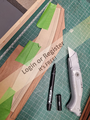
I began by using some thin cardboard to make some templates for the edging of the foredeck, a 10mm width of mahogany looks to be a nice proportion to the 6.5mm limewood planks.
You might expect that both the port and starboard card templates for the foredeck would be identical back-to-back but surprisingly that is not the case with a variation of a few mm in places. For this reason, separate templates were made and laid onto some 1.5mm mahogany sheet, the outlines marked and very carefully cut from the sheet with a very sharp blade.
With the mahogany, being so thin and the grain being quite coarse, there is the possibility that it can break across the grain, so great care is required to hold the sheet down firmly while being cut.
Similarly, I made card templates for the longer pieces that go back to the stern. The inner edges of all these mahogany pieces were smoothed with some abrasive paper. The outer edges slightly overlap the deck and will be trimmed and contoured before the gunwale strips are applied around the hull at a later stage.
An additional detail is a central mahogany strip on the foredeck that will be echoed on the very rear deck and access hatch. All of these pieces were fixed down with CA and I took great care to get a very tight join between the pieces for the best appearance.


I will also be adding a mahogany detail to the hull that follows the gunwale of the deck that will form a nice edge for the paint finish on the hull.
I began by using some thin cardboard to make some templates for the edging of the foredeck, a 10mm width of mahogany looks to be a nice proportion to the 6.5mm limewood planks.
You might expect that both the port and starboard card templates for the foredeck would be identical back-to-back but surprisingly that is not the case with a variation of a few mm in places. For this reason, separate templates were made and laid onto some 1.5mm mahogany sheet, the outlines marked and very carefully cut from the sheet with a very sharp blade.
With the mahogany, being so thin and the grain being quite coarse, there is the possibility that it can break across the grain, so great care is required to hold the sheet down firmly while being cut.
Similarly, I made card templates for the longer pieces that go back to the stern. The inner edges of all these mahogany pieces were smoothed with some abrasive paper. The outer edges slightly overlap the deck and will be trimmed and contoured before the gunwale strips are applied around the hull at a later stage.
An additional detail is a central mahogany strip on the foredeck that will be echoed on the very rear deck and access hatch. All of these pieces were fixed down with CA and I took great care to get a very tight join between the pieces for the best appearance.
▲
⟩⟩
jbkiwi
pressonreguardless
tonyb2
Madwelshman
chugalone100
JOHN
hermank
Mike W
Jay
AlessandroSPQR
EdW
RNinMunich
Rookysailor
Ronald
SimonB2
RossM
roycv
ChrisF
Missouri
|
💬 Re: Planking the deck. Part 1.
3 months ago by 🇬🇧 robbob (
Fleet Admiral)✧ 100 Views · 3 Likes
Flag
Hi Mike W.
"A very enjoyable read and an excellent build blog". Thank you for your kind comments, I'm pleased that you are enjoying reading my build blog 😊👍. Rob ▲
⟩⟩
Jay
tonyb2
Missouri
|
|
Login To
Remove Ads 💬 Re: Planking the deck. Part 1.
3 months ago by 🇺🇸 Hsailer (
 Leading Seaman) Leading Seaman)✧ 101 Views · 1 Like
Flag
A Great series to learn how to do some tricky planking projects.
▲
⟩⟩
hermank
|
|
💬 Re: Planking the deck. Part 1.
3 months ago by 🇬🇧 Mike W (
Leading Seaman)✧ 100 Views · 2 Likes
Flag
A very enjoyable read and an excellent build blog. It will be a lovely boat when she's finished. Inspiring - now where did I put my tools? 😊
▲
⟩⟩
robbob
hermank
|
|
💬 Re: Planking the deck. Part 1.
3 months ago by 🇬🇧 robbob (
Fleet Admiral)✧ 106 Views · 5 Likes
Flag
Hi Ronald.
"Are the planks of the upper decks to be the same width as the lower deck planks?" Yes, they will also be 1.6 x 6.5mm lime wood with .5mm black caulking lines and a high gloss epoxy resin finish. Rob. ▲
⟩⟩
tonyb2
Missouri
hermank
Jay
RossM
|
|
💬 Re: Planking the deck. Part 1.
3 months ago by 🇨🇦 Ronald (
Fleet Admiral)✧ 112 Views · 1 Like
Flag
Are the planks of the upper decks to be the same width as the lower deck planks?
▲
⟩⟩
hermank
|
📝 Planking the rear lower deck.
3 months ago by 🇬🇧 robbob ( Fleet Admiral)
Fleet Admiral)✧ 112 Views · 15 Likes · 4 Comments
Flag
💬 Add Comment
With all of the deck panels firmly glued in place and trimmed all round with a small hand plane I can now consider the rear lower deck floor.
As with the deck panels this is also laser etched with planking lines and at this stage of construction it would be impossible to apply my own planking and caulking lines in the deep recess.
My solution was to cut a piece of 2mm ply to form a new floor panel that I could plank as a separate panel that will be glued down over the laser etched floor. I marked out an aperture on the panel to fit around the motor mounting block.
To date this will be the largest area that I have attempted to plank and I also fear that the process will cause the panel to distort as the glues and resin finishes cure.
I began the process by marking a centre line and fixing down the 1.6mm x 6.5mm limewood strips and the .5mm black plasticard ‘caulking’ lines with superglue and working outwards symmetrically to, hopefully, minimise stresses in the panel.
I found that, although repetitive, the process was quite easy and enjoyable to do as there was no fiddly cutting and trimming of planks to perform.
Once the panel was fully covered I left it for a day or so for the glue to fully cure before trimming off the overlaps around the edges and paring the plasticard caulking down to an even surface with a sharp chisel.
I then cut out the aperture for the motor mounting block and did a test fit. A final rub down with 400 grit abrasive paper resulted in a fine finish ready for the first of several coats of epoxy finishing resin.
Thankfully at this stage there is no significant distortion of the panel so my fears were largely unfounded.
▲
⟩⟩
tonyb2
Madwelshman
Mike W
Jay
EdW
Missouri
Rogal118
RNinMunich
Chum444
Rookysailor
Ronald
PhilH
hermank
chugalone100
roycv
|
💬 Re: Planking the rear lower deck.
3 months ago by 🇬🇧 ChrisF (
Vice Admiral)✧ 111 Views · 3 Likes
Flag
I've done most of my planking with cyano which as you say you have to be careful that you don't stick yourself as well 😁 which worked well without distortion as it dries so fast.
I also tried aliphatic to give more positioning time but overnight that did cause distortion in the planking which fortunately I was able to sand out. Ronald - if you look at the Tools thread I have recommended cyanos that are odour free and don't affect me like the original cyanos do. It's good to have some again that I can use and I have used them a lot recently. I must try Superphatic for planking which is another odour free glue that gives more time. ▲
⟩⟩
Madwelshman
Ronald
hermank
|
|
Login To
Remove Ads 💬 Re: Planking the rear lower deck.
3 months ago by 🇬🇧 robbob (
Fleet Admiral)✧ 112 Views · 6 Likes
Flag
Hi Ronald.
"Is it possible to use a different glue if a person doesn’t tolerate CA?" Fortunately I don't have any intolerance to CA, but I am very careful not to stick myself to anything with it! I find it perfect for fixing the planking strips and plasticard as the 'grab' time is just right to allow placing the lime strip and pressing it firmly into place. Similarly for the plasticard 'caulking' strips. Its use does allow for very quickly covering the required area without needing to hold anything in place with pins, clamps or tape, as you might if you used wood glue, which wouldn't be suitable for the plastic anyway, or any other form of adhesive. As I say, it works for me, but perhaps others could offer an alternative for those that have a reaction to CA? Rob. ▲
⟩⟩
tonyb2
Mike W
Jay
Missouri
Ronald
hermank
|
|
💬 Re: Planking the rear lower deck.
3 months ago by 🇺🇸 chugalone100 (
Captain)✧ 112 Views · 2 Likes
Flag
Beautiful job, very realistic.
😎 ▲
⟩⟩
hermank
robbob
|
|
💬 Re: Planking the rear lower deck.
3 months ago by 🇨🇦 Ronald (
Fleet Admiral)✧ 117 Views · 2 Likes
Flag
Do I understand the process correctly? You are gluing the lime wood and plastic card strips to the plywood using CA ?
Is it possible to use a different glue if a person doesn’t tolerate CA? ▲
⟩⟩
hermank
robbob
|


Login To
Remove Ads
Remove Ads