
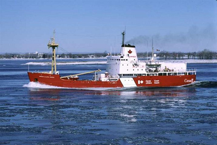
C.C.G.S Norman McLeod Rogers

By Seaspray 46 entries 12 Apr 2021 — 19 Sep 2022
118Likes
151Comments
Chapter 31 / 46

46 chapters · Page 4 of 5

Norman McLeod Rogers

Rudder/ servo Pic 1. Firstly had to find the height of the servo arm to the tiller arm. Made a support out of ply to mount the servo making sure the servo wires would go through it. Fitted the rubbers / screws / cups to servo lugs. Made blocks of wood to glue to the underside of the top plate with servo sitting on top for ground clearance. Ply with cut out for servo glued in place onto blocks and servo screwed into place making sure only the lugs were supporting the servo. Linages / rods cut to size and fitted to tiller / servo arms with a little backlash. Job done work fine. Next the props.
Liked by Colin H

Norman Mcleod Rogers

Propshafts. Had to retake these images this morning.
Props drilled out for oil feeders and a drill inserted to align the feeder with the oil hole and screws tightened. Completed props with propeller on and their lock nuts tightened. Slots drilled and filed in hull to take the shafts ( no images). Pic 3. Shafts aligned and secured in hull with filler. Next time I will use epoxy to secure shafts into the hull as I believe gives a smoother finish but this is good filler. This is a mess in Pic 4. Lastly 4 images of the propshafts outside the hull. The propellers are 4 bladed left and right with a width of 40 mm
Liked by LaphonS and Colin H and

Norman Mcleod Rogers

Cut the propshafts support from 2mm ply taken from a cardboard template. Iffy about the glue to use settle on Epoxy 5 minute curing time. First batch I used took 1 hour to cure so it was binned and new Epoxy use with a recut support. Hopefully I have came far enough down the prop tube to give a good support and will clean up the area add a little PVA to fill in gaps. Meantime have cut some lead (1.93 mm) to shape n size fitted it in the hull temporary. This will be adjusted when the model is complete as the superstructure and other things come into the overall weight of the model.
Liked by Colin H

Norman McLeod Rogers

First pic. shows the angle the anchor sits in its compartment. Not having that room inside the hull I just made square boxes for them to sit inside. The box sides had to be at an angled to fit in this small area. Pic 2,3 the anchors are glued in place. This area is to be sprayed black and having lots of damaged the outer edge of the compartment, it will be cleaned up later. I might put an edging around the edge this'll make it better looking. Next pic. are the propshaft supports sanded and cleaned up. When spraying the hull I think it is a good idea not to spray the propshafts. Lastly the anchors bought from Hobbies a lot dearer than the last ones but good quality.
Liked by Colin H

Norman McLeod Rogers

Motor installation. Will be using two Graupner 600 ECO motor. One turning clockwise the other anti clockwise. Firstly the spec of the motors. I will either run on 7.2v or 8.4v battery packs. Next is the two motors with their mounts and securing screws. Like to use these cheese head screws with allen key inserts. Was hoping to use the couplings but after fitting my alignment tool, there isn't much room under the motor even with the mounts removed also its sits above 1.5mm planking. Pause till I up load the second idea.
Liked by Colin H

Norman McLeod Rogers

Second Idea was to use a pulley system. The pulleys I am considering using. Second from top packet wasn't 4mm inside diameter, so had to drill two of the pulleys to 4mm. As you can see they're a nice sliding fit. The bottom left one didn't did like the drilling the others came good. Next motors with pulleys on a nice fit as the shafts 4mm. on props and3.17 mm. on motors. Offered the full setup into position. Only problem is when tension is added to the belts. The motors bend their mounts with the back lifting away from the mount. Will look into this when I decide what method will use. I prefer the coupling method, never had any trouble with them even the I.C. days
Liked by stevedownunder and Julio and

Norman McLeod Rogers

Here is a " See how it goes". Roughly laid out and haven't done the motor mounts. Cut a big area out of the rudder frame as I was havening trouble lining up the allen key that tightens the tiller arm. Thought I'd knocked a hole in the planking but it was a piece of stray harddrive I broke up yesterday and it flew into a hundred pieces.
Liked by Colin H

Norman McLeod Rogers

Had a relook and altered the motors mounting to cut down some weight and have the ESC moved out of the hot air from the motor fans. Not too happy with the layout of the wire on the ESA. Have to be careful not to touch the +ve or -ve wire on the battery connectors and motors to the Rx and on/off switch. I am I being a wee bit cautious.
Liked by Colin H

Norman McLeod Rogers

Finally the motors in position and secured. Bored 2 holes each side / rear of the motors. Before this I got the motors to the right height. ( see the thin ply below the mounts ) screwed motors down tight added a premeasured piece of scrap below rear of each motor to get the right angle in line with the propshafts. Threaded the plastic tie thru the hole and s a piece of thin wire thru the opposite hole. Bored a little hole in the tye threaded the wire thru it. This helped get the tie thru the hole from the bottom. Secured motor but haven't cut off the extra on the tye just in case need reworked.
Liked by Colin H

Norman McLeod Rogers

Built a battery box for the 2 power packs. I did think it would be tight getting them in and out of the model. Looking at cutting the (call it the work deck) around where the pencil line is. Tom made the hatches bigger, on his mode and that worked for him. Another thing I don't like cutting the top of the frames to gain easy access to the hull.
Liked by Colin H

Delete this post?

It will be removed from the site.

Discard this draft?

Your draft will be deleted and cannot be recovered.

You have an unfinished draft

What would you like to do with it?